SANY Crawler Hydraulic Excavator (SY195C9, SY205C9, SY215C9, SY225C9). Shop Manual (2013) - page 11
Structure and Function
6
7
5
8
4
9
3
10
2
1
A-A
ZX215-1002114
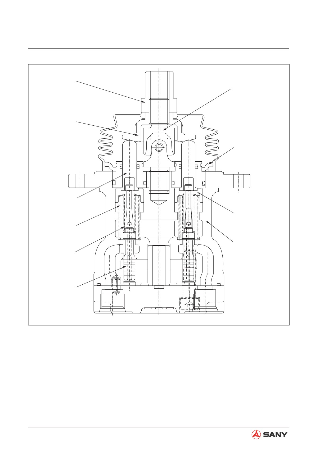
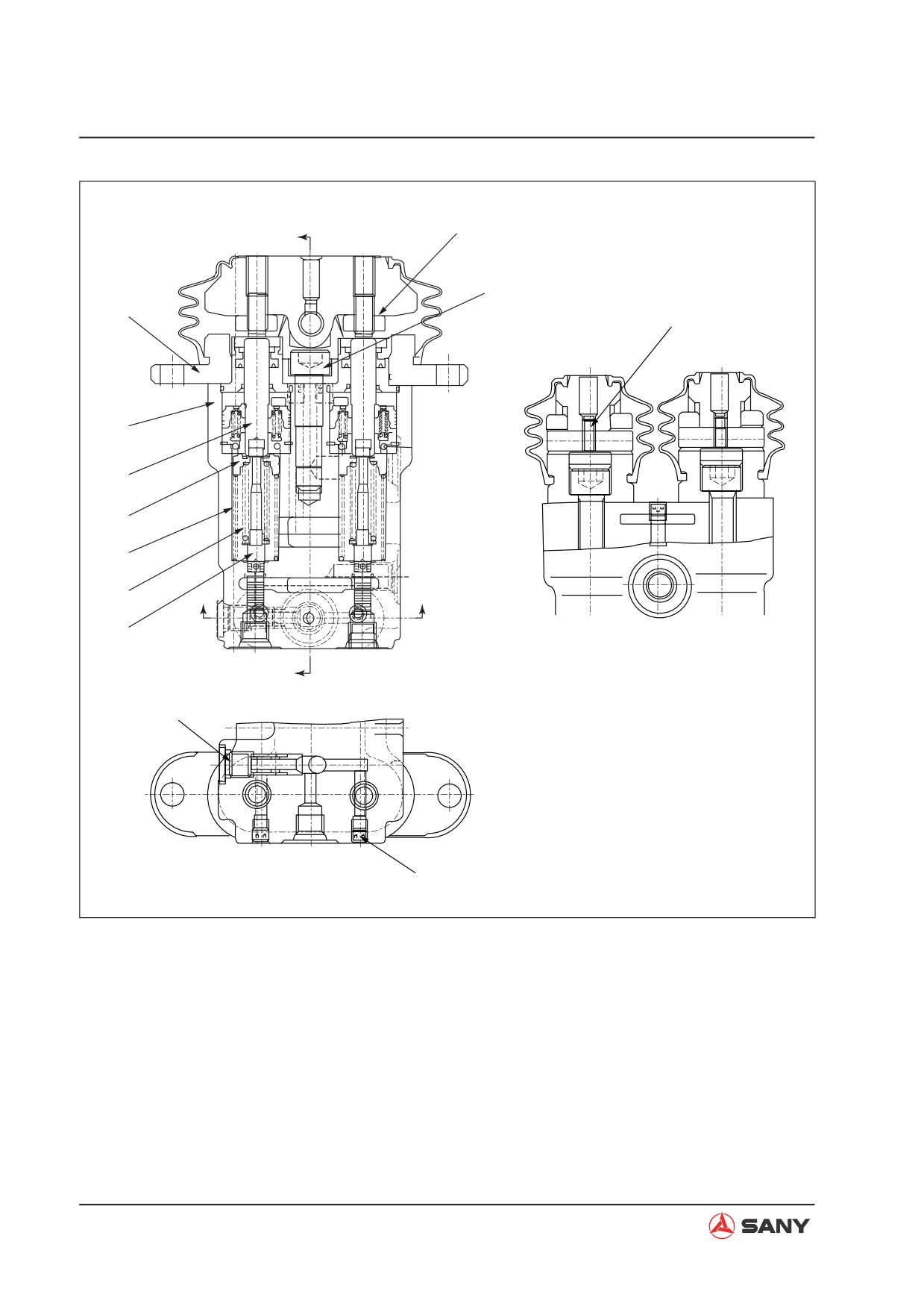
1) Plunger
6) Nut (for lever connection)
2) Metering spring
7) Joint
3) Centering spring
8) Plate
4) Piston
9) Retainer
5) Disc
10) Valve body
4-110
Structure and Function
Operation
1.
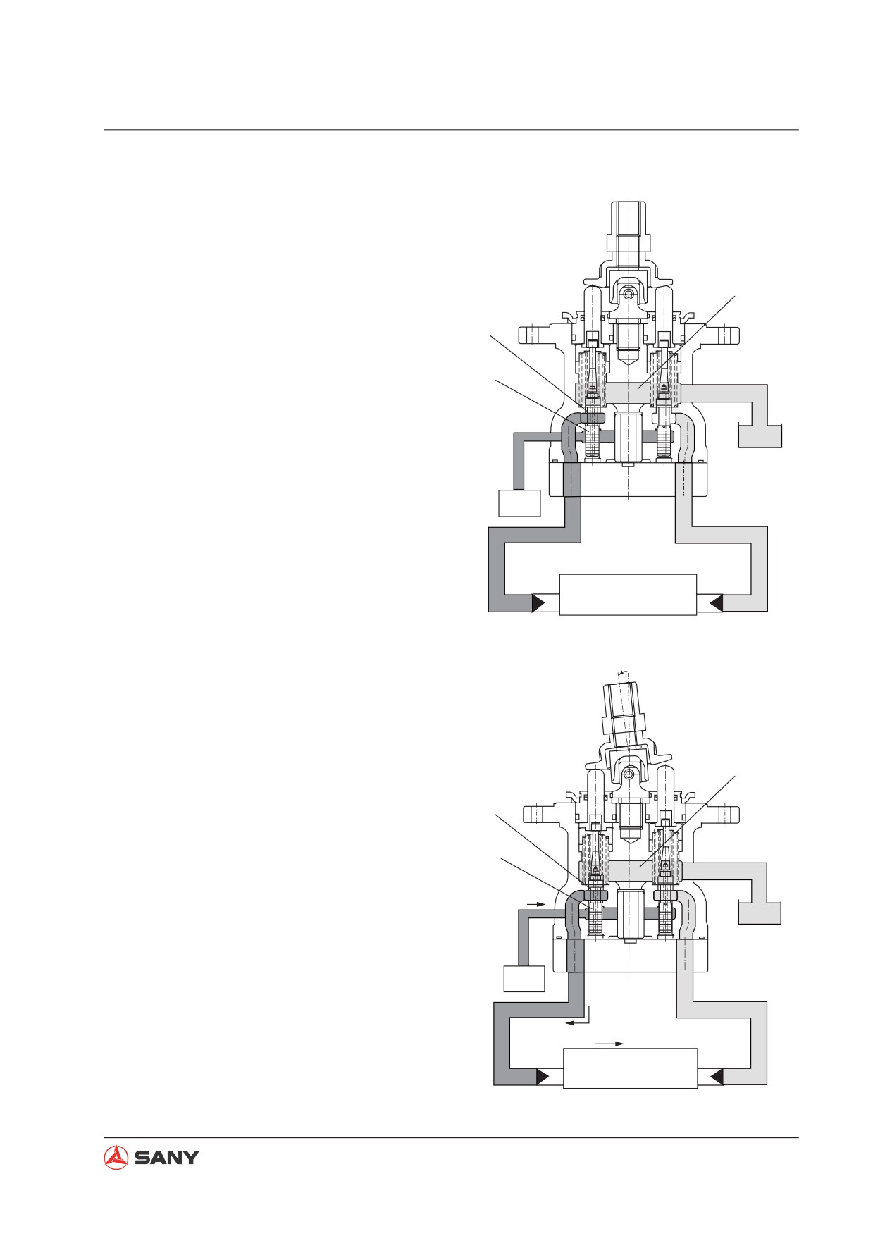
When in neutral
Ɣ
Ports (A) and (B) of the control valve and
ports (P1) and (P2) of the pilot valve are
connected to drain chamber (D) via orifice
D
(f) in plunger (1).
f
2.
Fine control (Neutral to fine control)
1
T
Ɣ
When piston (4) is pushed by disc (5),
retainer (9) is pushed, plunger (1) is also
P
pushed by metering spring (2), and moves
down.
Ɣ
When orifice (f) is shut off from drain cham-
Pilot
pump
P1
P2
ber (D), it is almost simultaneously inter-
connected to pump pressure chamber (PP).
Pilot pressurized oil of the control pump is
led to port (A) from port (P1) via orifice (f).
A
M
M B
Control valve
When the pressure at port (P1) becomes
higher, plunger (1) is pushed back and
ZX215-1002115
orifice (f) is shut off from pump pressure
chamber (PP). At almost the same time, it
is connected to drain chamber (D) to re-
lease the pressure at port (P1). As a result,
plunger (1) moves up and down until the
force of metering spring (2) is balanced
with the pressure at port (P1).
D
Ɣ
The relationship of the position of plunger
f
(1) and body (10) [orifice (f) is in the middle
between drain chamber (D) and pump
1
T
pressure chamber (PP)] does not change
until retainer (9) contacts plunger (1). Me-
P
tering spring (2) contracts in proportion to
the stroke of the control lever. Pressure
at port (P1) also rises in proportion to the
stroke of the control lever. In this way, the
Pilot
control valve spool moves to a position
pump
P1
P2
where the pressure of chamber (A) (same
as pressure at port (P1)) and the force of
the return spring of the control valve spool
A
M
M
B
are balanced.
Control valve
ZX215-1002116
4-111
Structure and Function
3.
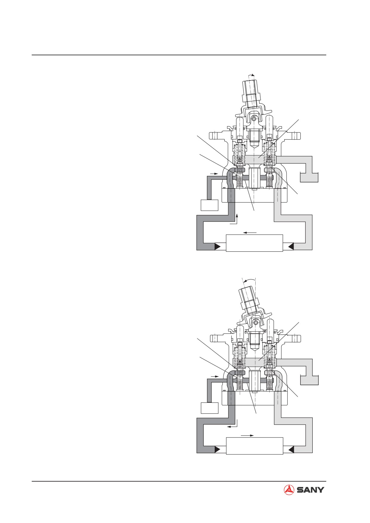
During fine control (When control lever
is returned)
Ɣ
When disc (5) starts to return, plunger
(1) is pushed up by the force of centering
spring (3) and the pressure at port (P1).
D
Ɣ
Because of this, orifice (f) is connected to
f
drain chamber (D), and the pressurized oil
at port (P1) is released.
1
T
Ɣ
If the pressure of port (P1) is lowered ex-
P
cessively, plunger (1) is pushed down by
metering spring (2).
f1
Ɣ
Orifice (f) is shut off from drain chamber
Pilot
pump
P1
P2
(D), and it is almost simultaneously in-
PP
terconnected to pump pressure chamber
(PP). Pump pressure is supplied until the
pressure at port (P1) recovers to the level
A
M
M
B
equivalent to the lever position.
Control valve
ZX215-1002117
Ɣ
When the spool of the control valve re-
turns, the oil in drain chamber (D) flows in
from orifice (f) in the valve on the side that
is not working. The oil passes through port
(P2) and enters chamber (B) to replenish
the chamber with pressurized oil.
D
4.
At full stroke
f
Ɣ
Disc (5) pushes down piston (4), and re-
tainer (9) pushes down plunger (1).
1
T
Ɣ
Orifice (f) is shut off from drain chamber (D),
and is interconnected to pump pressure
P
chamber (PP).
Ɣ
Therefore, the pilot pressure oil from
f1
the self pressure reducing valve passes
Pilot
pump
P1
P2
through orifice (f) and flows to chamber
PP
(A) from port (P1) to push the control valve
spool.
A
M
M B
Control valve
Ɣ
The oil returning from chamber (B) passes
from port (P2) through orifice (f) and flows
ZX215-1002118
to drain chamber (D).
4-112
Structure and Function
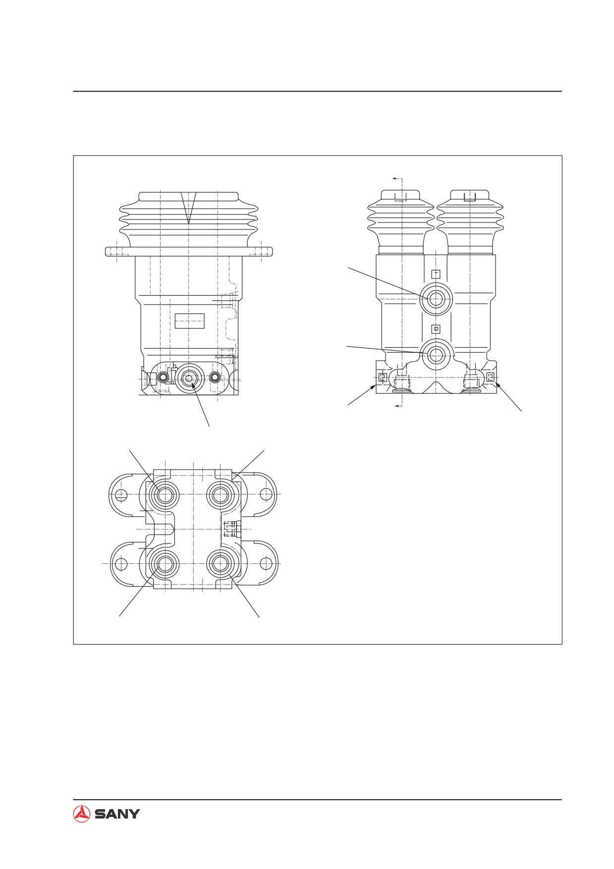
4.6.8.2 Travel PPC valve
A
T
T
P
P
P5
A
P6
P5
P2
P1
2
1
4
3
P4
P3
ZX215-1002119
P: From pilot pump
P4: R.H. forward
P1: L.H. reverse
P5: Travel signal
P2: L.H. forward
P6: Travel signal
P3: R.H. reverse
T: To tank
4-113
Structure and Function
37~30Nm
B
65~45Nm
1
8~6Nm
2
3
4
5
6
C
C
7
B-B
2đ4
1đ3
B
13~11Nm
C-C
8~6Nm
ZX215-1002120
1) Plate
5) Centering spring
2) Body
6) Metering spring
3) Piston
7) Valve
4) Collar
4-114
Structure and Function
Operation
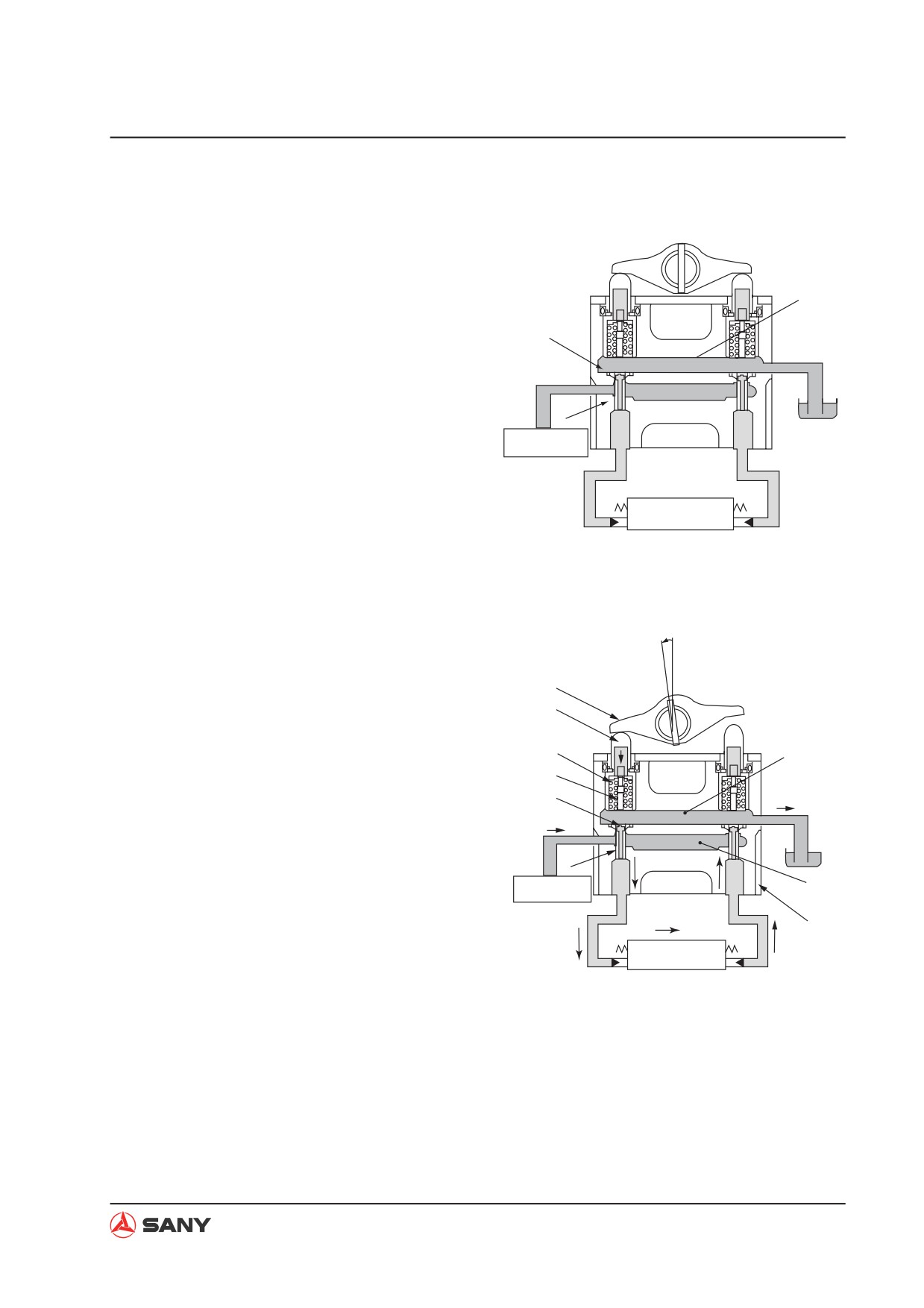
1.
When in neutral
Ɣ
Ports (A) and (B) of the control valve and
ports (P1) and (P2) of the Pilot valve are
D
connected to drain chamber (D) via orifice
(f) in plunger (1).
f
T
2.
Fine control (Neutral to fine control)
P
Ɣ
When piston (4) is pushed by lever (5),
1
retainer (9) is pushed, plunger (1) is also
Pilot pump
pushed by metering spring (2), and moves
P1
P2
down. When orifice (f) is shut off from drain
chamber (D), it is almost simultaneously
A
B
Control valve
interconnected to pump pressure chamber
(PP).
ZX215-1002121
Ɣ
Pilot pressurized oil of the control pump is
led to port (A) from port (P1) via orifice (f).
Ɣ
When the pressure at port (P1) becomes
higher, plunger (1) is pushed back and
orifice (f) is shut off from pump pressure
5
chamber (PP). At almost the same time, it
4
is connected to drain chamber (D) to re-
lease the pressure at port (P1).
9
D
Ɣ
As a result, plunger (1) moves up and
2
down until the force of metering spring (2)
f
T
is balanced with the pressure at port (P1).
P
Ɣ
The relationship of the position of plunger
1
(1) and body (10) [orifice (f) is in the middle
Pilot pump
PP
between drain chamber (D) and pump
P1
P2
pressure chamber (PP)] does not change
10
until retainer (9) contacts plunger (1).
A
B
Control valve
Ɣ
Metering spring (2) contracts in proportion
ZX215-1002122
to the stroke of the control lever.
Ɣ
Pressure at port (P1) also rises in propor-
tion to the stroke of the control lever.
Ɣ
In this way, the control valve spool moves
to a position where the pressure of cham-
ber (A) (same as pressure at port (P1)) and
the force of the return spring of the control
valve spool are balanced.
4-115
Structure and Function
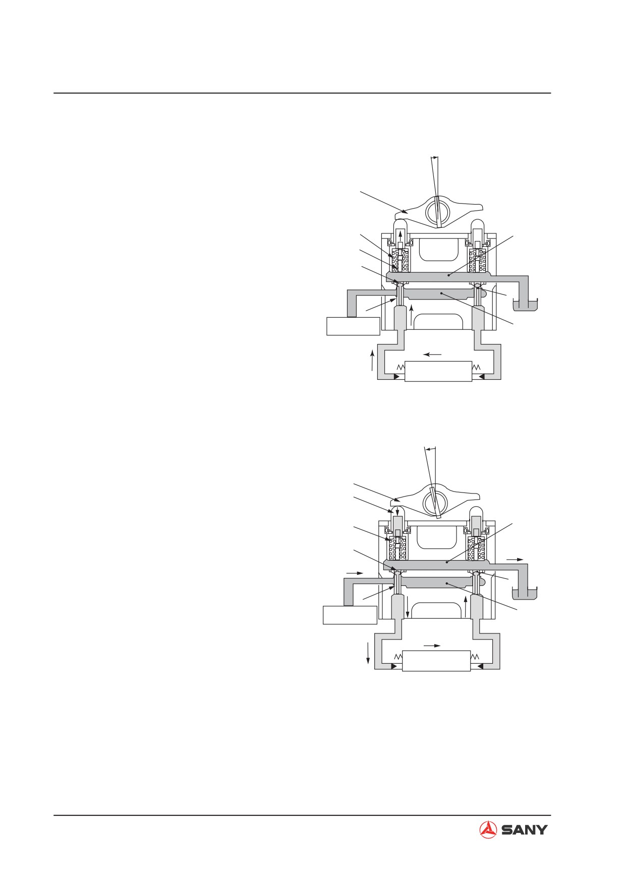
3.
Fine control (When control lever is
returned)
Ɣ
When lever (5) starts to return, plunger
(1) is pushed up by the force of centering
5
spring (3) and pressure at port (P1).
Ɣ
Because of this, orifice (f) is connected to
3
D
drain chamber (D), and the pressurized oil
2
at port (P1) is released.
f
T
Ɣ
If the pressure of port (P1) is lowered ex-
P
cessively, plunger (1) is pushed down by
f’
metering spring (2).
1
Pilot pump
PP
Ɣ
Orifice (f) is shut off from drain chamber (D),
P1
P2
and it is almost simultaneously intercon-
nected to pump pressure chamber (PP).
A
B
Control valve
ZX215-1002123
Ɣ
Pump pressure is supplied until the pres-
sure at port (P1) recovers to the level
equivalent to the lever position.
Ɣ
When the spool of the control valve re-
turns, the oil in drain chamber (D) flows in
from orifice (f) in the valve on the side that
5
is not working. The oil passes through port
4
(P2) and enters chamber (B) to replenish
9
D
the chamber with pressurized oil.
4.
At full stroke
f
T
P
Ɣ
Lever (5) pushes down piston (4), and re-
f’
tainer (9) pushes down plunger (1).
1
Pilot pump
PP
Ɣ
Orifice (f) is shut off from drain chamber (D),
P1
P2
and is interconnected to pump pressure
chamber (PP).
A
B
Control valve
Ɣ
Therefore, the pilot pressure oil from
ZX215-1002124
the self pressure reducing valve passes
through orifice (f) and flows to chamber
(A) from port (P1) to push the control valve
spool.
Ɣ
The oil returning from chamber (B) passes
from port (P2) through orifice (f) and flows
to drain chamber (D).
4-116
Structure and Function
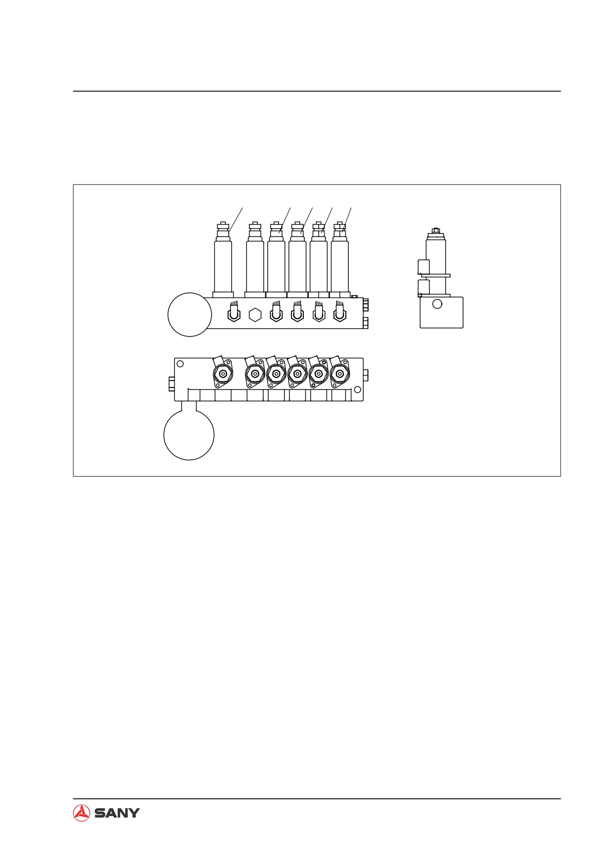
4.6.9 Solenoid valve
Pilot valve lock, travel speed, bucket confluence, swing priority
1
2
3
4
5
T
A6
A4
A3
A2
A1
P1
WX13060401
1) Travel hi/lo speed solenoid valve
T:
To oil tank
2) Swing priority solenoid valve
P:
From accumulator and pilot pump
3) Bucket confluence solenoid valve
A1 To center swivel joint port
4) Boom to arm priority solenoid valve
A2 To main valve port PsP
5) Pilot lockout solenoid valve
A3 To main valve port Xbp2
A4 To main valve port PnA2
A6 To pilot valve block P
NOTE: For the location of the solenoid valve on the machine, see “Hydraulic equipment layout”
on page 4-24.
4-117
Structure and Function
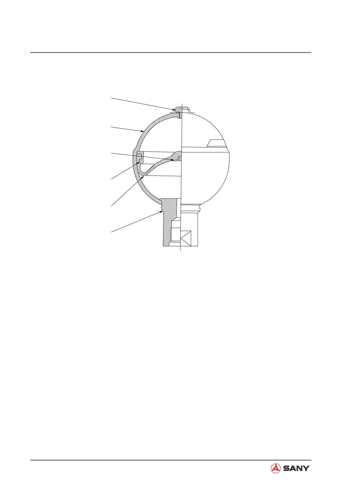
4.6.10 Accumulator
1
2
3
4
5
6
ZX215-1002126
1) Gas plug
Specifications
2) Shell
Gas capacity: 300 cm³
3) Poppet
4) Holder
5) Bladder
6) Oil port
4-118
Structure and Function
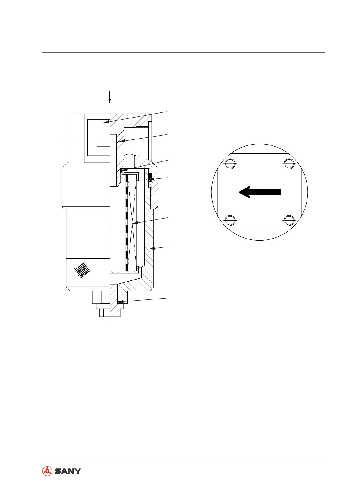
4.6.11 Pilot oil filter
K
1
K
2
ݼ
৯
ࣚ؇
3
4
5
6
3
ZX215-1002127
Specifications
1) Name plate
Max. delivery: 40 L/min
2) Head cover
Filter fineness: 10 ȝm
3) O-ring
Operating pressure: 20 Mpa
4) Seal
Max. operating pressure: 40 Mpa
5) Filter
Pressure loss: 0.05 Mpa
6) Case
Max. allowable pressure difference: 1 Mpa
Specification of inlet/outlet port o-ring: 30×3.1
4-119
Structure and Function
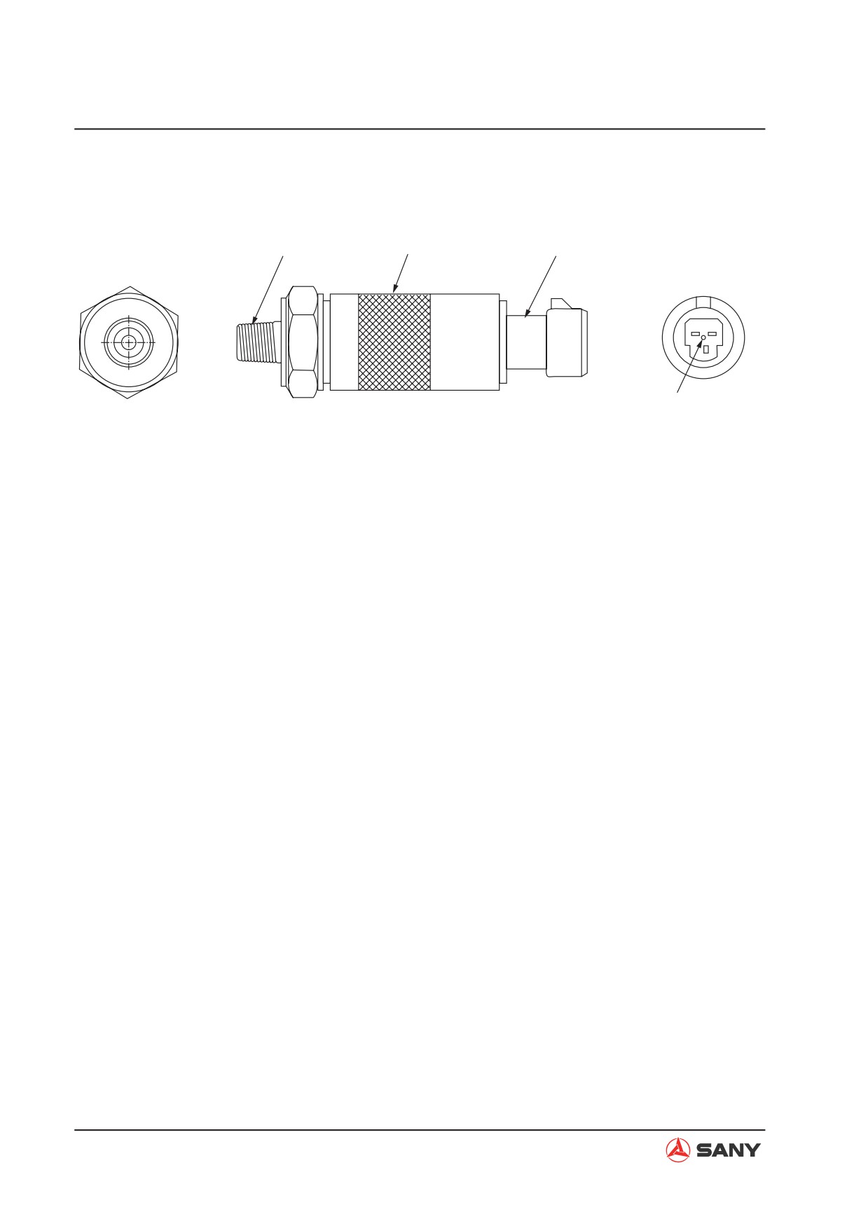
4.6.12 Pump oil pressure sensor
1
2
3
A B
C
4
ZX215-1002128
1) Pressure connector
2) Name plate
3) Connector
4) Vent hole
Function
Ɣ This sensor measures pump oil pressure
and uses it to control various machine op-
erations. When oil pressure compresses
the diaphragm, it deforms and this is de-
tected in the form of electric signals.
4-120
Structure and Function
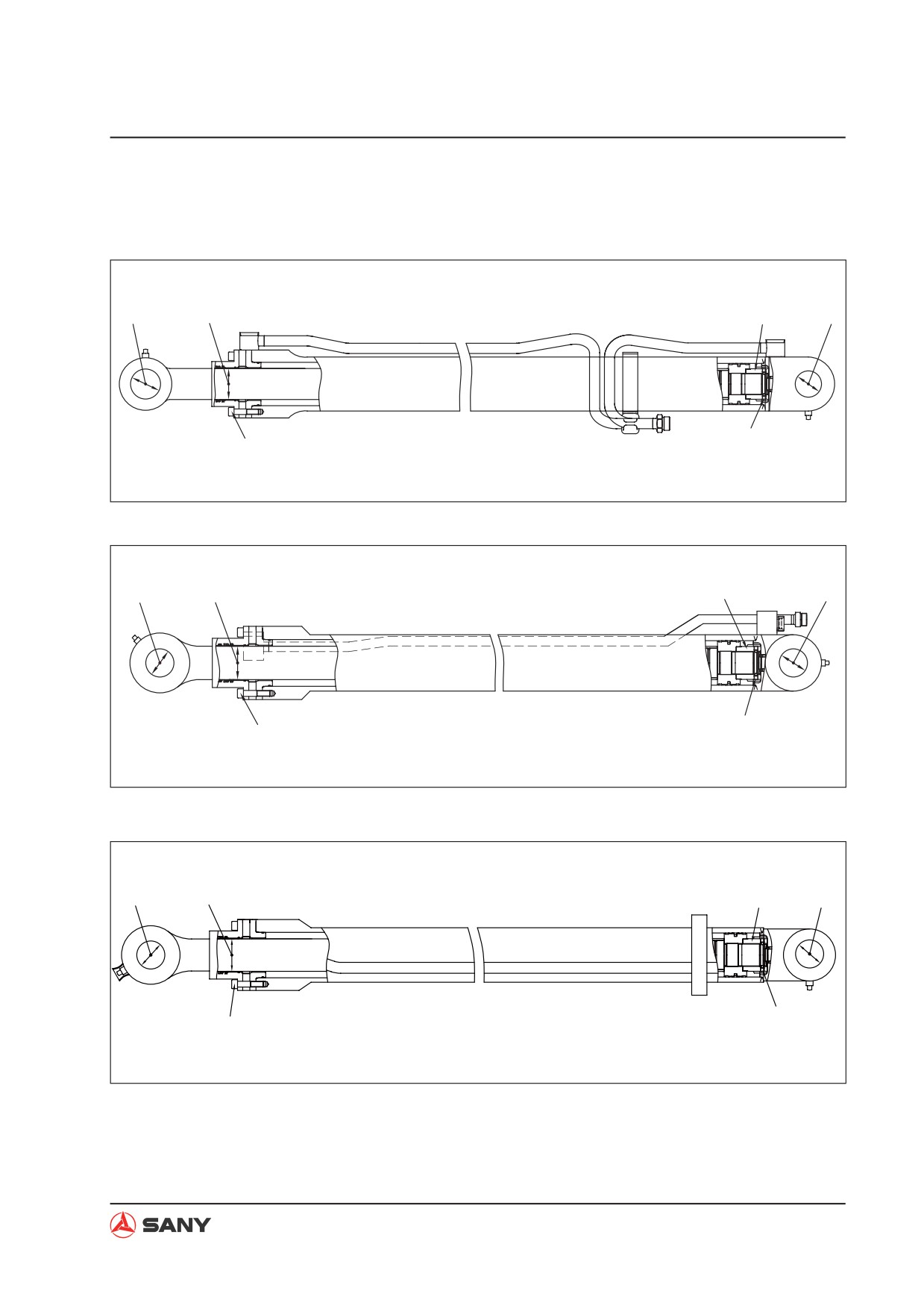
4.6.13 Hydraulic cylinder
Boom cylinder
5340±50N·m
2
1
544.9±5.1kgm
3
56.9±10.7N·m
267±35N·m
5.8±1.1kgm
27.2±3.6kgm
ZX215-1002129
Arm cylinder
7900±50N·m
806.1±5.1kgm
2
1
3
56.9±10.7N·m
367±35N·m
5.8±1.1kgm
37.4±3.6kgm
ZX215-1002130
Bucket cylinder
5480±50N·m
2
1
559.2±5.1kgm
3
56.9±10.7N·m
267±35N·m
5.8±1.1kgm
27.2±3.6kgm
ZX215-1002131
4-121
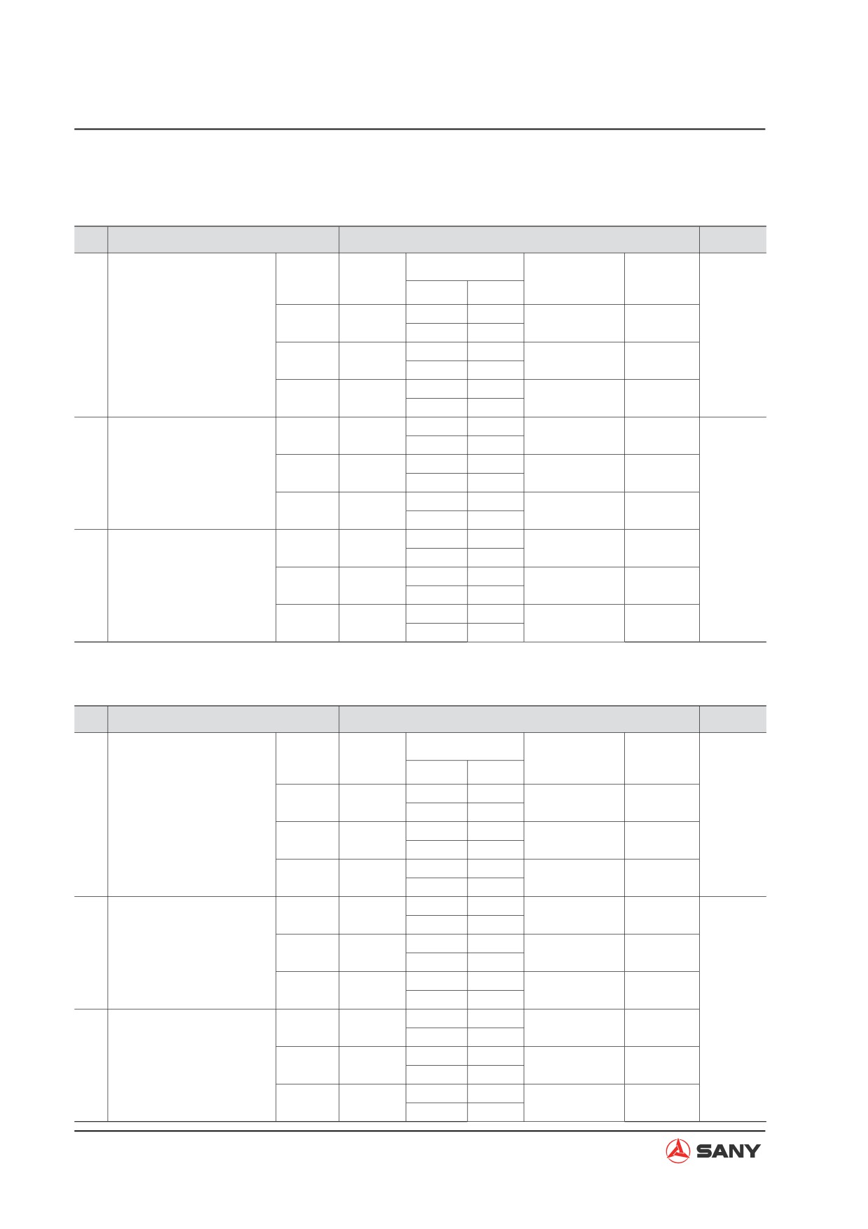
Structure and Function
100 hours greasing
Unit: mm
No.
Check item
Criteria
Remedy
Standard
Tolerance
Standard
Clearance
Cylinder
size
Shaft
Hole
clearance
limit
-0.036
+0.222
Clearance between pis-
Boom
85
0.083
- 0.312
0.412
Replace
1
-0.090
+0.047
ton rod and bushing
bushing
-0.036
+0.222
Arm
95
0.083
- 0.312
0.412
-0.090
+0.047
-0.030
+0.258
Bucket
80
0.078
- 0.334
0.434
-0.076
+0.048
-0.030
+0.246
Boom
80
0.230
- 0.322
1.0
-0.076
+0.200
Clearance between pis-
-0.030
+0.246
2
ton rod support pin and
Arm
80
0.230
- 0.322
1.0
-0.076
+0.200
bushing
-0.030
+0.246
Bucket
70
0.230
- 0.322
1.0
Replace
-0.076
+0.200
pin or
-0.030
+0.246
Boom
70
0.230
- 0.322
1.0
bushing
-0.076
+0.200
Clearance between cyl-
-0.030
+0.246
3
inder bottom support pin
Arm
80
0.230
- 0.322
1.0
-0.076
+0.200
and bushing
-0.030
+0.246
Bucket
70
0.230
- 0.322
1.0
-0.076
+0.200
500 hours greasing
Unit: mm
No.
Check item
Criteria
Remedy
Standard
Tolerance
Standard
Clearance
Cylinder
size
Shaft
Hole
clearance
limit
-0.036
+0.222
Clearance between pis-
Boom
85
0.083
- 0.312
0.412
Replace
1
-0.090
+0.047
ton rod and bushing
bushing
-0.036
+0.222
Arm
95
0.083
- 0.312
0.412
-0.090
+0.047
-0.030
+0.258
Bucket
80
0.078
- 0.334
0.434
-0.076
+0.048
-0.030
+0.246
Boom
80
0.230
- 0.322
1.0
-0.076
+0.200
Clearance between pis-
-0.030
+0.246
2
ton rod support pin and
Arm
80
0.230
- 0.322
1.0
-0.076
+0.200
bushing
-0.030
+0.246
Bucket
70
0.230
- 0.322
1.0
Replace
-0.076
+0.200
pin or
-0.030
+0.246
Boom
70
0.230
- 0.322
1.0
bushing
-0.076
+0.200
Clearance between cyl-
-0.030
+0.246
3
inder bottom support pin
Arm
80
0.230
- 0.322
1.0
-0.076
+0.200
and bushing
-0.030
+0.246
Bucket
70
0.230
- 0.322
1.0
-0.076
+0.200
4-122
Structure and Function
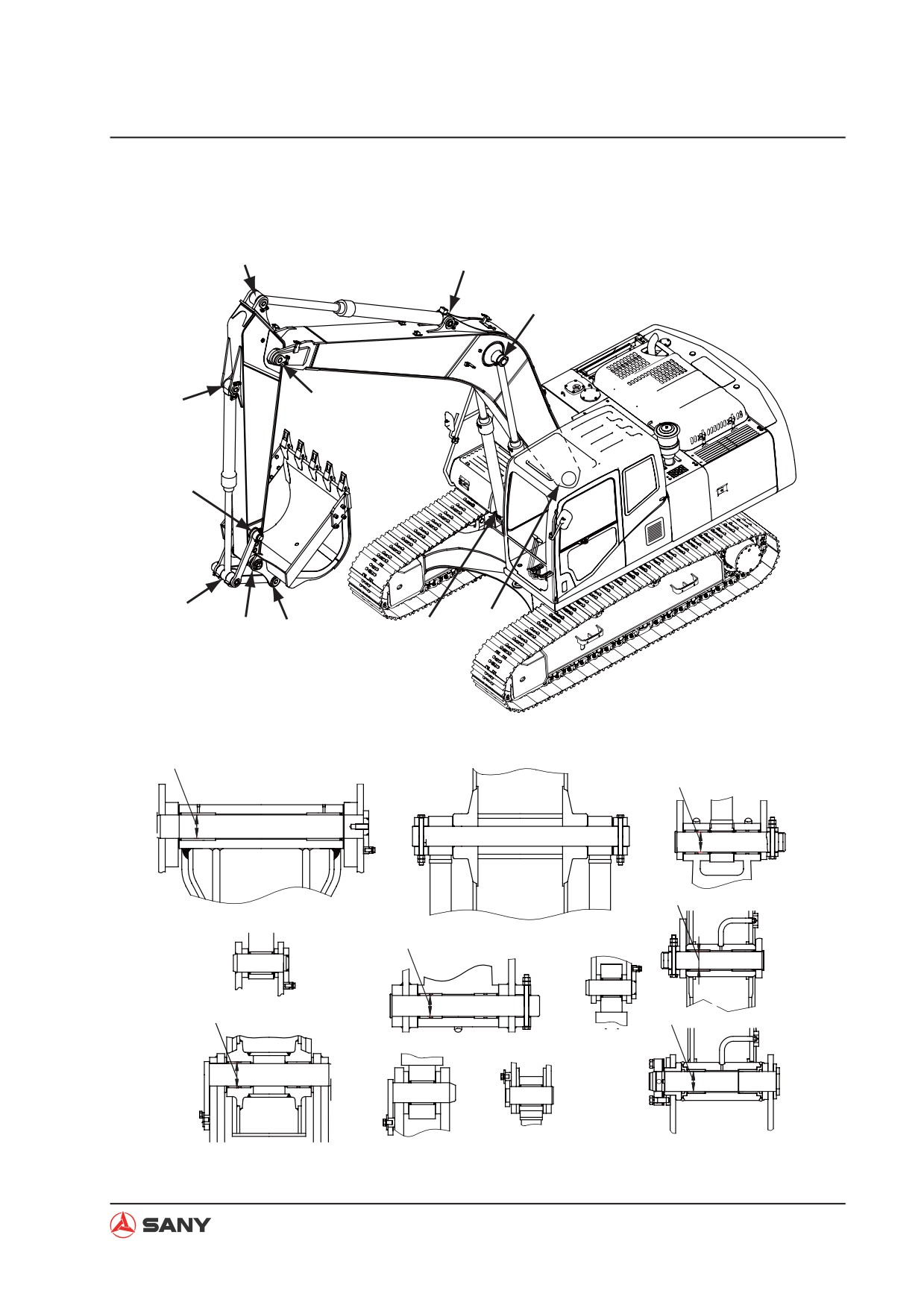
4.6.14 Work equipment
F
D
C
G
E
J
,
A
B
K
H
ZX215-1002133
1
6
,-,
3
A-A
C-C
5
B-B
2
4
J-J
G-G
H-H
K-K
E-E
D-D
F-F
ZX215-1002134
4-123
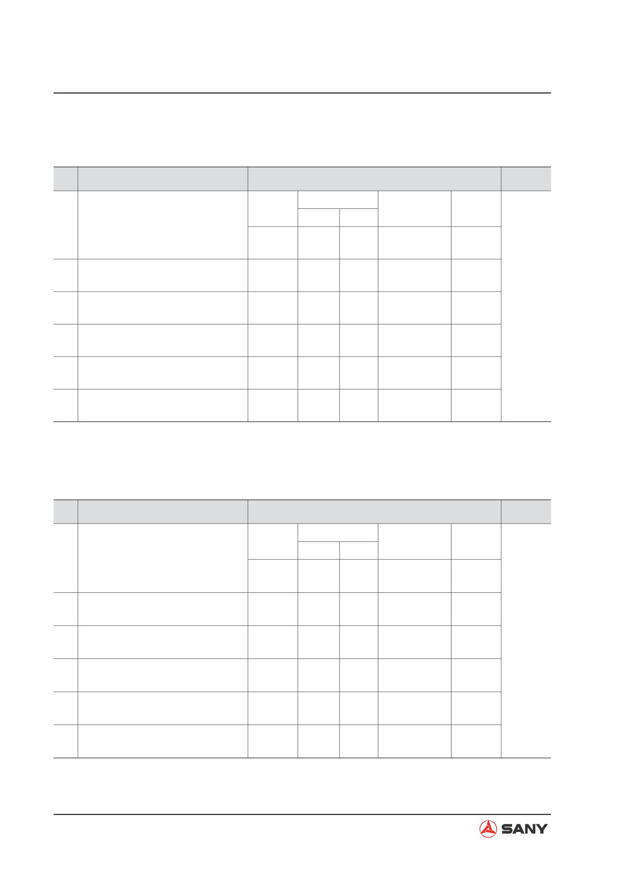
Structure and Function
100 hour greasing
Unit: mm
No.
Check item
Criteria
Remedy
Standard
Tolerance
Standard clear-
Clearance
Clearance between pin connect-
size
Shaft
Hole
ance
limit
1
ing boom and revolving frame and
–0.036
+0.140
bushing
90
0.141 ~ 0.211
1.0
–0.071
+0.105
Clearance between pin connecting
-0.036
+0.174
2
90
0.140 ~ 0.345
1.0
boom and arm and bushing
–0.071
+0.104
Clearance between pin connecting
-0.030
+0.335
3
70
0.305 ~ 0.395
1.0
Replace
arm and rocker and bushing
–0.060
+0.275
Clearance between pin connecting
-0.030
+0.324
4
80
0.300 ~ 0.384
1.0
arm and bucket and bushing
–0.060
+0.270
Clearance between pin connecting
-0.030
+0.373
5
80
0.303 ~ 0.433
1.0
linkage and bucket and bushing
–0.060
+0.273
Clearance between pin connecting
-0.030
+0.335
6
70
0.305 ~ 0.395
1.0
linkages and bushing
–0.060
+0.275
500 hour greasing
Unit: mm
No.
Check item
Criteria
Remedy
Standard
Tolerance
Standard clear-
Clearance
Clearance between pin connect-
size
Shaft
Hole
ance
limit
1
ing boom and revolving frame and
–0.036
+0.131
bushing
90
0.110 ~ 0.202
1.0
–0.071
+0.074
Clearance between pin connecting
-0.036
+0.166
2
90
0.110 ~ 0.237
1.0
boom and arm and bushing
–0.071
+0.074
Clearance between pin connecting
-0.030
+0.158
3
70
0.108 ~ 0.218
1.0
Replace
arm and rocker and bushing
–0.060
+0.078
Clearance between pin connecting
-0.030
+0.137
4
80
0.104 ~ 0.197
1.0
arm and bucket and bushing
–0.060
+0.074
Clearance between pin connecting
-0.030
+0.166
5
80
0.116 ~ 0.226
1.0
linkage and bucket and bushing
–0.060
+0.086
Clearance between pin connecting
-0.030
+0.154
6
70
0.104 ~ 0.214
1.0
linkages and bushing
–0.060
+0.074
4-124
Structure and Function
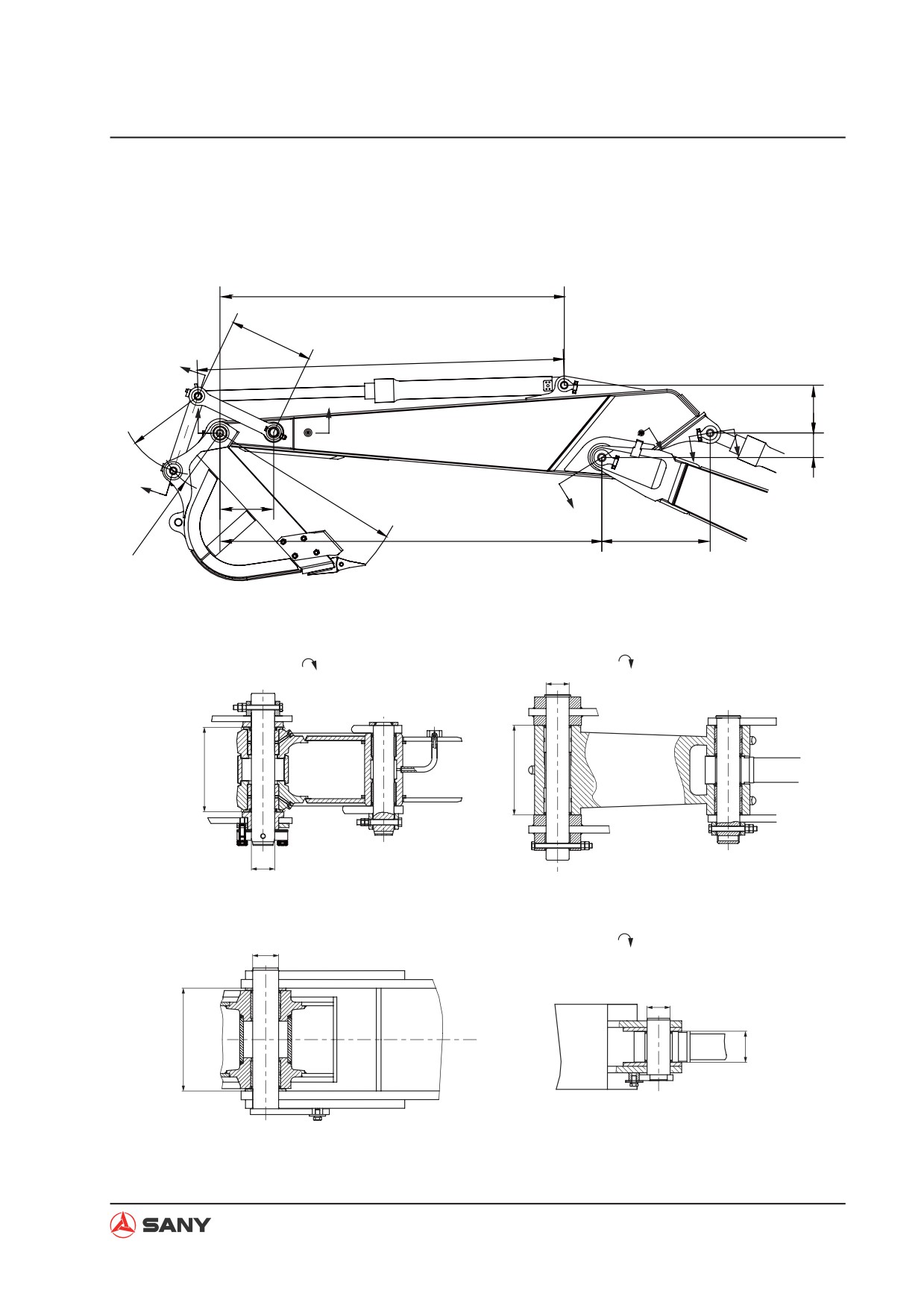
Arm dimension
9
11
B
19
12
5
C
A
D
A
6
D
B
14
C
10
8
7
13
A-A
B-B
15
18
16
17
C-C
D-D
4
1
3
2
WX13060402
4-125
Structure and Function
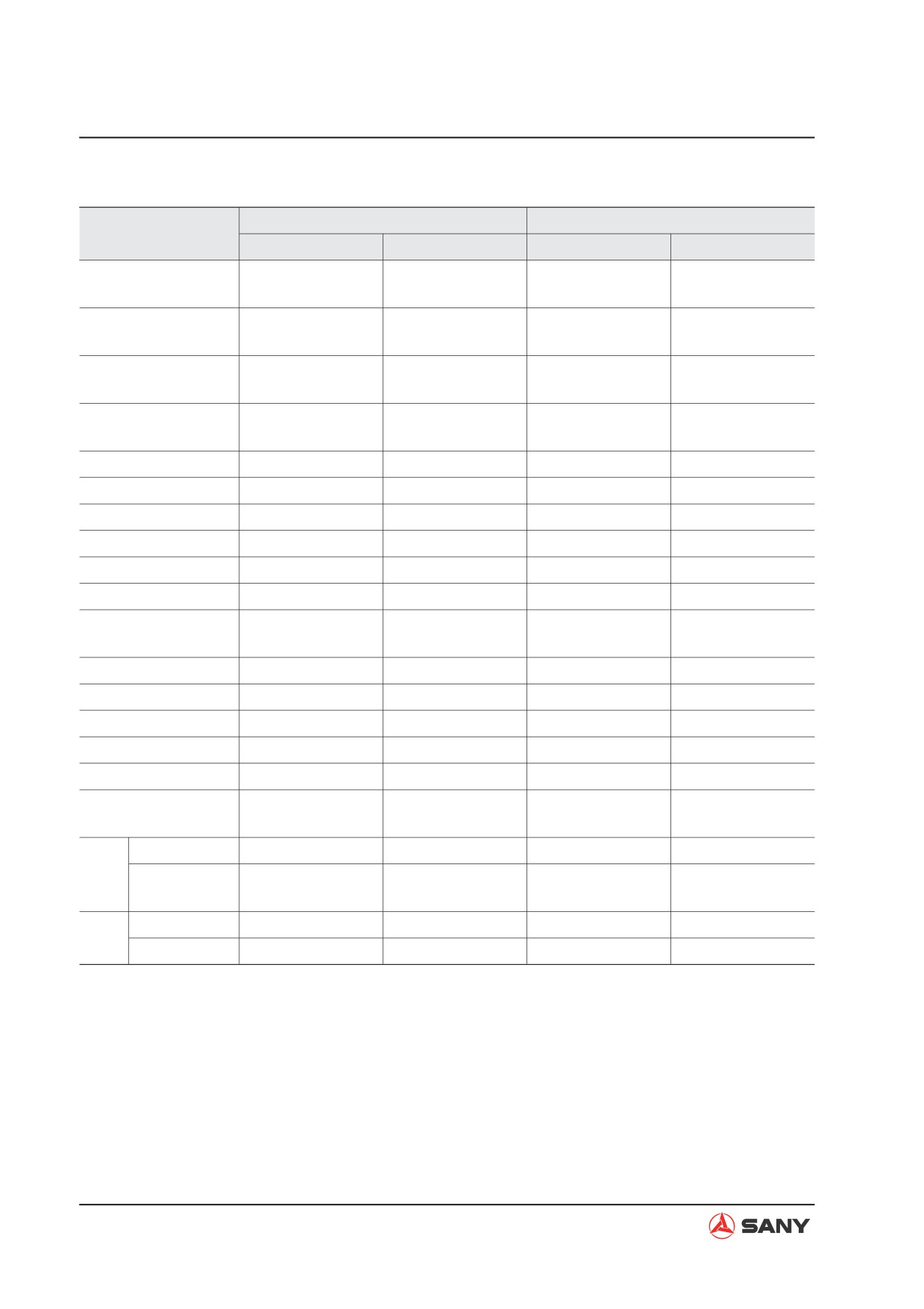
Unit: mm
SY195/205/215C-9
SY225C-9
No.
Standard size
Tolerance
Standard size
Tolerance
+0.1
+0.1
1
ij80
ij80
0
0
±0.5
±0.5
2
107
107
0
0
-0.3
-0.3
3
310
310
-0.8
-0.8
-0.036
-0.036
4
ij90
ij90
-0.071
-0.071
5
549
±1
549
±1
6
158
±0.8
158
±0.8
7
835
±1
835
±1
8
2,911
±2
2,911
±2
9
2,643
±2
2,643
±2
10
411
±0.8
411
±0.8
0
0
11
640
640
-0.5
-0.5
12
600
—
600
—
13
458
—
458
—
14
1,483
—
1,495
—
15
ij80
—
ij80
—
16
326.5
—
326.5
—
+0.2
+0.2
17
ij80
ij80
0
0
Arm itself
311
—
311
—
18
When press fit-
325
—
325
—
ting bushing
Min.
1,680
—
1,680
—
19
Max.
2,800
—
2,800
—
4-126
Structure and Function
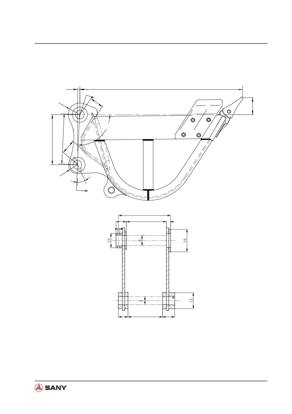
Bucket dimension
2
5
A
18
17
6
3
1
4
16
19
7
A
12
11
9
10
13
20
21
22
A-A
WX13060403
4-127
Structure and Function
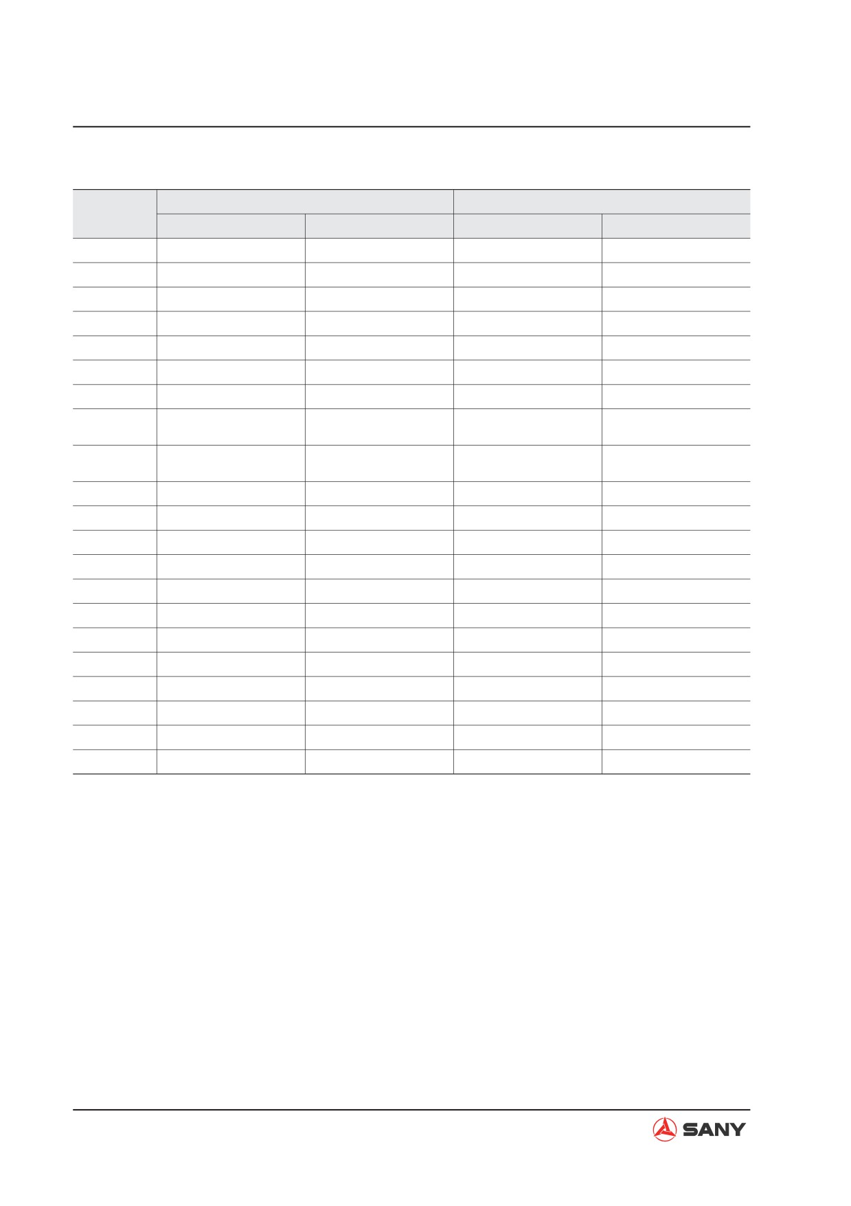
Unit: mm
SY195/205/215C-9
SY225C-9
No.
Standard size
Tolerance
Standard size
Tolerance
1
457.5
±0.5
457.5
±0.5
2
22
±0.5
22
±0.5
3
91.8°
—
91.8°
—
4
458
—
458
—
5
1,483
—
1,483
—
6
177
—
177
—
7
45°
—
45°
—
+0.2
+0.2
8
ij80
ij80
0
0
+0.2
+0.2
9
348.5
348.5
0
0
10
37
—
37
—
11
107
—
107
—
12
473.5
—
473.5
—
13
ij23.5
—
ij23.5
—
14
ij190
—
ij190
—
15
ij136
—
ij136
—
16
131
—
131
—
17
125
—
125
—
18
R180
—
R180
—
19
R140
—
R140
—
20
57
—
57
—
21
326.5
±0.5
326.5
±0.5
4-128
Structure and Function
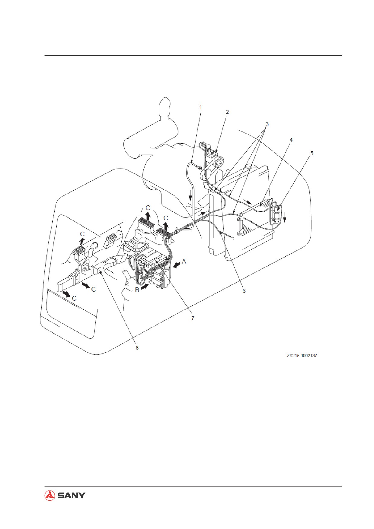
4.7 Air Conditioning System
1) Hot water piping
A. Fresh air
2) A/C compressor (DENSO.2)
B. Recirculated air
3) Refrigeration piping
C. Warm air/cool air
4) Condenser (SG447750-A040)
5) Receiver tank (DENSO.4)
6) Hot water return piping
7) A/C unit assembly (SG443180-9320)
8) Air duct
4-129