SANY Crawler Hydraulic Excavator (SY195C9, SY205C9, SY215C9, SY225C9). Shop Manual (2013) - page 10
Structure and Function
A:
From main valve BTL
B:
From main valve BTR
C:
From main valve ATL
D:
From main valve ATR
A1:
To L. travel motor port (P1)
B2:
To R. travel motor port (P2)
C3: To L. travel motor port (P2)
D4: To R. travel motor port (P1)
G:
To swing motor port DB
G1: From travel motor final drive assembly oil drain port (D1,D2)
F:
From solenoid valve port A2
F1:
To travel motor reducer Hi/Lo speed switching port (P)
4-90
Structure and Function
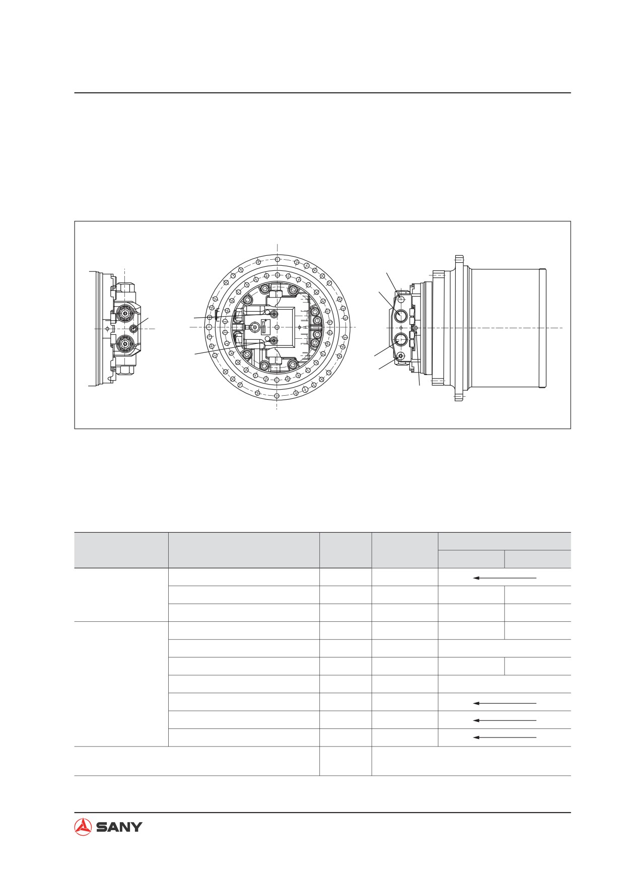
4.6.6 Travel motor
Model: TM40VD-A-99/163-1
NOTE: For the location of the travel motor on the machine, see “Hydraulic equipment layout” on
page 4-24.
D1
A
P
P1
P2
B
D2
P5
WX215-1204014G
Ps:
Duo speed pilot hose port
D1:
Drain port
P1:
Pressure detection port
D2:
Plug
P2:
Pressure detection port
A:
Main oil port
P5:
Parking brake release port
B:
Main oil port
Working condition
Speed 1
Speed 2
Gear ratio
49.95
Reduction gear
Theoretical output torque
(kgf.m)
Max. 4650
4535
2767
Theoretical output speed
(r.p.m)
Max. 60
28
45.9
Displacement
(cc/rev)
Max. 174.7
162.9
99.4
Continuous pressure
(kgf/cm2)
Max. 350
350
Theoretical speed
(r.p.m)
Max. 2800
1400
2294
Hydraulic motor
Flow
(l/min)
250
228
Duo speed control pressure
(kgf/cm2)
20~70
Braking torque
(kgf.m)
Min. 50
Brake release pressure
(kgf/cm2)
8.2
1~3L/min (above 365)
Relief valve activation pressure
15L/min (above 420)
4-91
Structure and Function
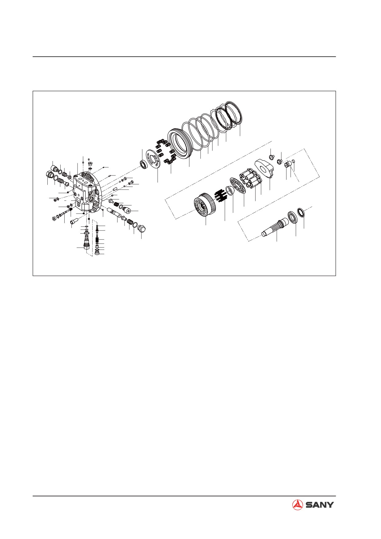
Explosive view
37
38
46
50
43
42
15
40
41
5
10
1
44
8
22
6
34
11
35
47
14
48
49
21
33
3
9
19
7
42
4
15
27
20
21
6
30
23 24
8
29
10
14
31
5
15
32
18
15
17
2
36
54
25
52
28
55
4
12
51
7
39
56
9
58
45
3
57
26
53
59
13
16
WX215-1204013G
1) Flange, rear
16)
Plug
31) Baffle
46)
Ball bearing
2) H5 balance valve
17)
Spool
32) Spheric bush
47)
Spring
spool
18)
Spring
33) Timing plate
48)
Piston
3) Plug
19)
Ball
34) Parking piston
49)
Stopper
4) D type block
20)
Orifice
35) Spring
50)
Pivot
5) Check plug
21)
O-ring
36) C y l i n d e r b l o c k
51)
Plunger
6) Check valve
spring
22)
Filter
52)
Piston seal
7) Spring
23)
Name plate
37) Friction plate
53)
Valve body
8) Stop spring
24)
Rivet
38) Spacer
54)
Washer
9) O-ring
39) Oil seal
25)
Plug
55)
O-ring
10) O-ring
40) O-ring
26)
Drive shaft
56)
O-ring
11) Parallel pin
41) O-ring
27)
P-type swash
57)
Shim
12) Socket head bolt
plate
42) Parallel pin
58)
Spring
13) O-ring
28) Cylinder block
43) Washer
59)
Piston rod
14) Plug
29) Piston
44) Washer
15) Plug
30) Stopper
45) Ball bearing
4-92
Structure and Function
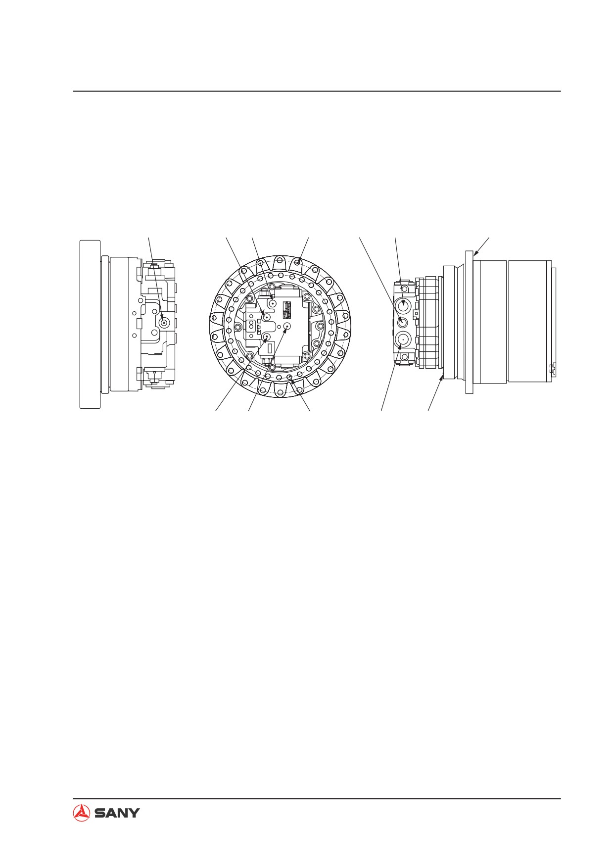
Model: MAG-170VP-3400E
NOTE: For the location of the travel motor on the machine, see “Hydraulic equipment layout” on
page 4-24.
Ps
Pm1
Tin
1
Dr
P1
A
Pm2
Pp
2
P2
B
ZX215-1002132
Ps:
Duo speed pilot hose port
A. Mounting surface with sprocket
Pm1: Pressure detection port
B. Mounting surface with undercarriage
Pm2: Pressure detection port
1. Mounting hole with sprocket
Tin:
Motor case inner oil port
2. Mounting hole with undercarriage
Pp:
Brake release port
Dr:
Oil drain port
P1:
Main oil port
P2:
Main oil port
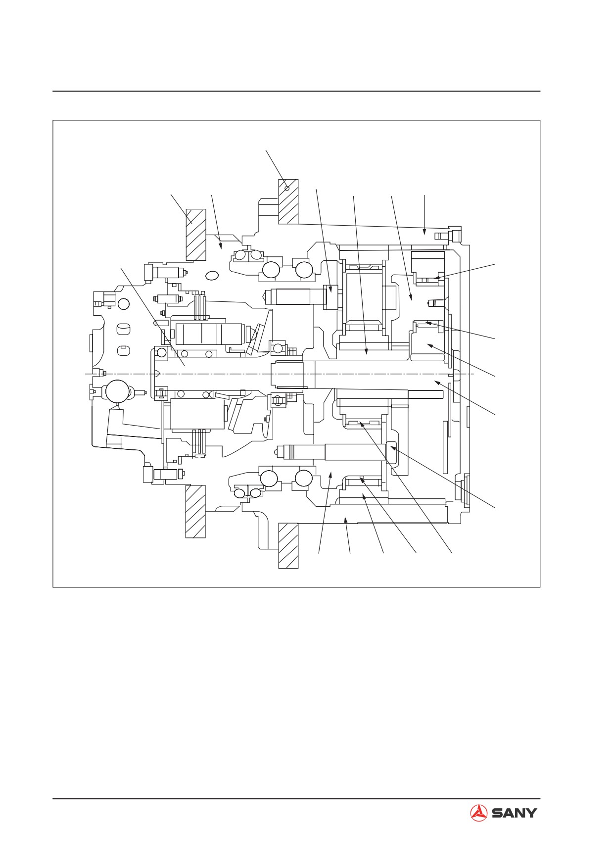
NOTE: For more technical information about the travel motor, see “Travel motor” on page 3-7.
4-93
Structure and Function
Connected to sprocket
Mounted on the undercarriage
5
4
2-1
1-4
1-3
Piston motor shaft
1-5
1-6
1-2
1-1
3
2-4
2-3
2-2
2-6
2-5
ZX215-1002093
4-94
Structure and Function
4.6.6.1 Operation of components
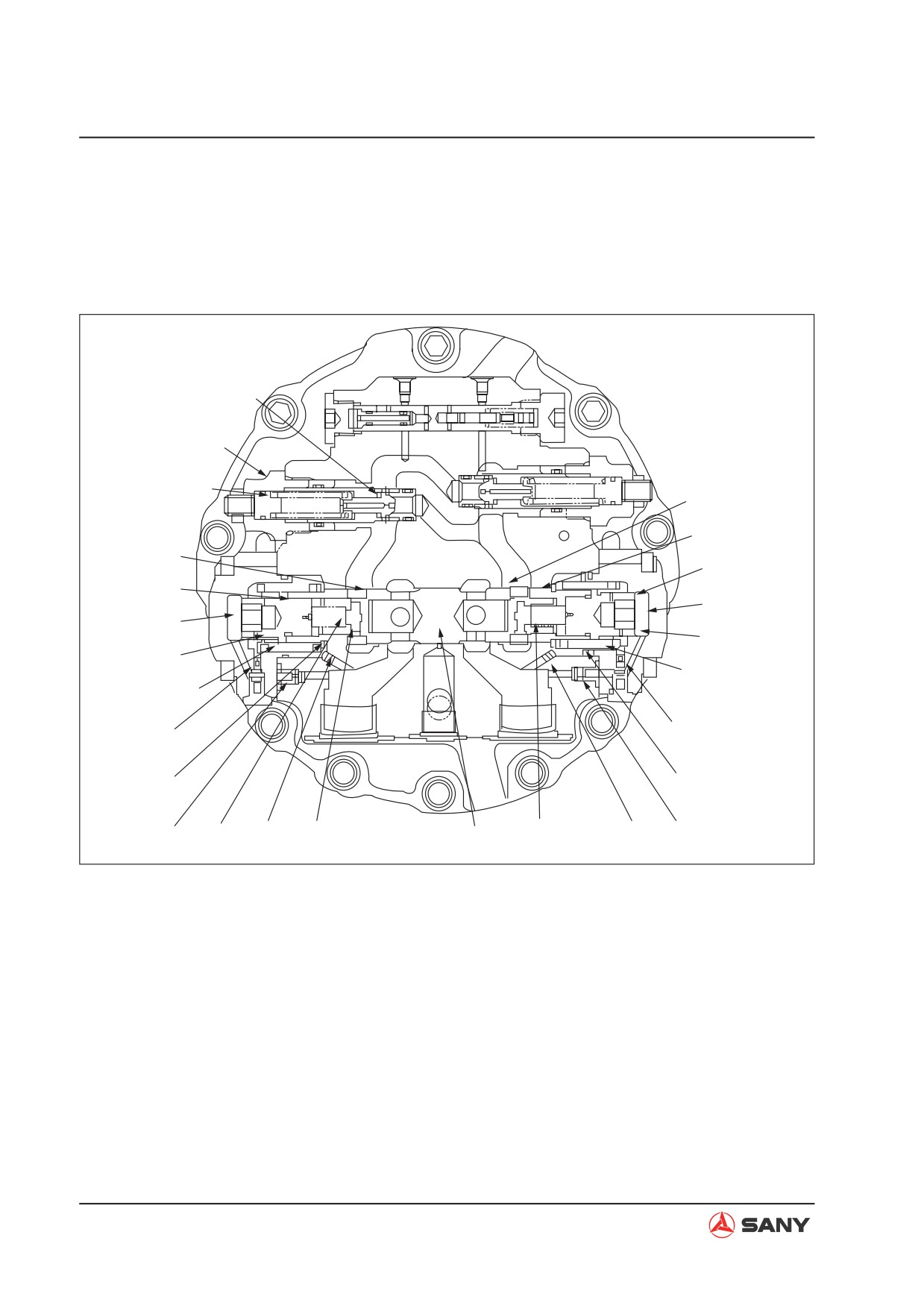
Counterbalance valve
Function
Ɣ When external load makes the rotating
speed of the piston motor faster than the
rated rotating speed of supplied delivery,
this valve controls the speed of the motor
and prevent over-speed of the motor in re-
lation with the supplied delivery.
Ɣ The counterbalance valve and the relief
valve constitute the braking circuit. The
braking circuit applies braking force onto
the rotating motor and stops the motor
gradually.
Ɣ This valve can serve as a shuttle valve
for high pressure selection to release the
brake under its own pressure.
Ɣ The structure of a standard counterbalance
valve is shown as below. The following in-
formation describes the operating principle
of a standard counterbalance valve.
4-95
Structure and Function
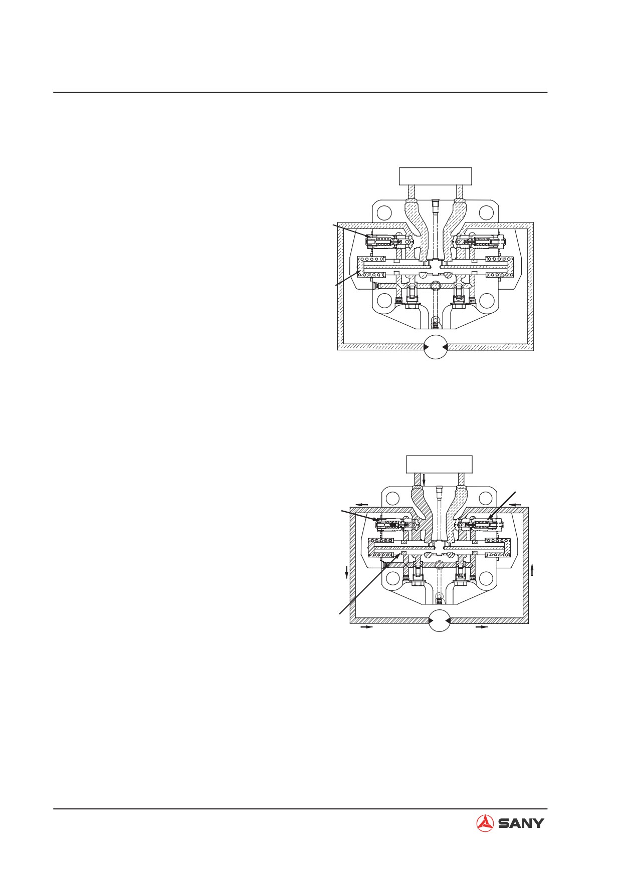
A. Stopped state
Ɣ When the main valve is neutralized (motor
pressure is generated at port P1 and port
stopped), port M1 and port M2 are shut off
P2. The motor is not rotating.
by spool (1) and check valve (2) since no
8-1
8
8-2
Circuit B
Circuit C2
Circuit C1
M1
M2
Orifice D3
Orifice D1
Damper chamber A2
Damper chamber A1
Orifice D4
Orifice D2
Spring chamber 2
Spring chamber 1
P1
P2
6-2
6-1
7-1
7-2
5-1
3
4-1
2-1
1
2-2
4-2
5-2
ZX215-1002094
4-96
Structure and Function
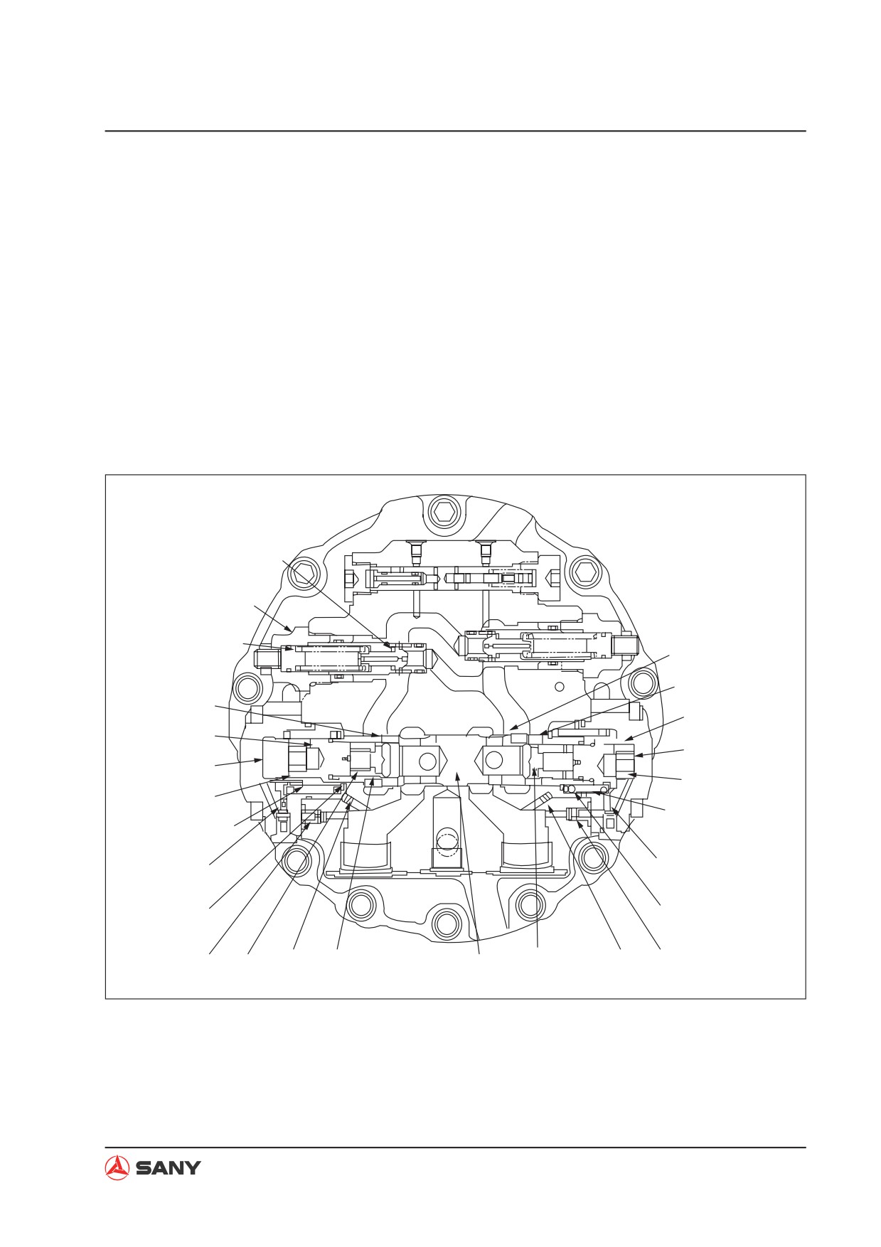
B. When the motor is activated
Ɣ When hydraulic oil from the main pump
damper chamber (A1) via orifice (4-1) and
enters port P1 of the counterbalance valve,
check valve (5-1). The force generated in
spring (3) is pushed to the left by check
this way pushes spring (7-2) on the other
valve (2-1), opening circuit C1. The hy-
side and moves piston (1) to the right. At
draulic oil enters the piston motor via port
this time, return oil from port M2 passes
M, trying to make the motor rotating. At the
through circuit of the notch on the periph-
same time, return oil from the piston motor
ery of piston (1), and through port P2 when
enters the counterbalance via port M2, but
pressure is generated at port M2, and en-
it is stopped by check valve (2-2). The out-
ters the tank via the main valve finally. The
put pressure of the main pump increases
motor is activated at this time.
as a result, and the hydraulic oil works
on the inside of spring chamber (1) and
8-1
8
8-2
Circuit B
Circuit C2
Circuit C1
M1
M2
Orifice D3
Orifice D1
Damper chamber A2
Damper chamber A1
Orifice D4
Orifice D2
Spring chamber 2
Spring chamber 1
P1
P2
6-2
6-1
7-2
7-1
5-1
3
4-1
2-1
1
2-2
4-2
5-2
ZX215-1002095
4-97
Structure and Function
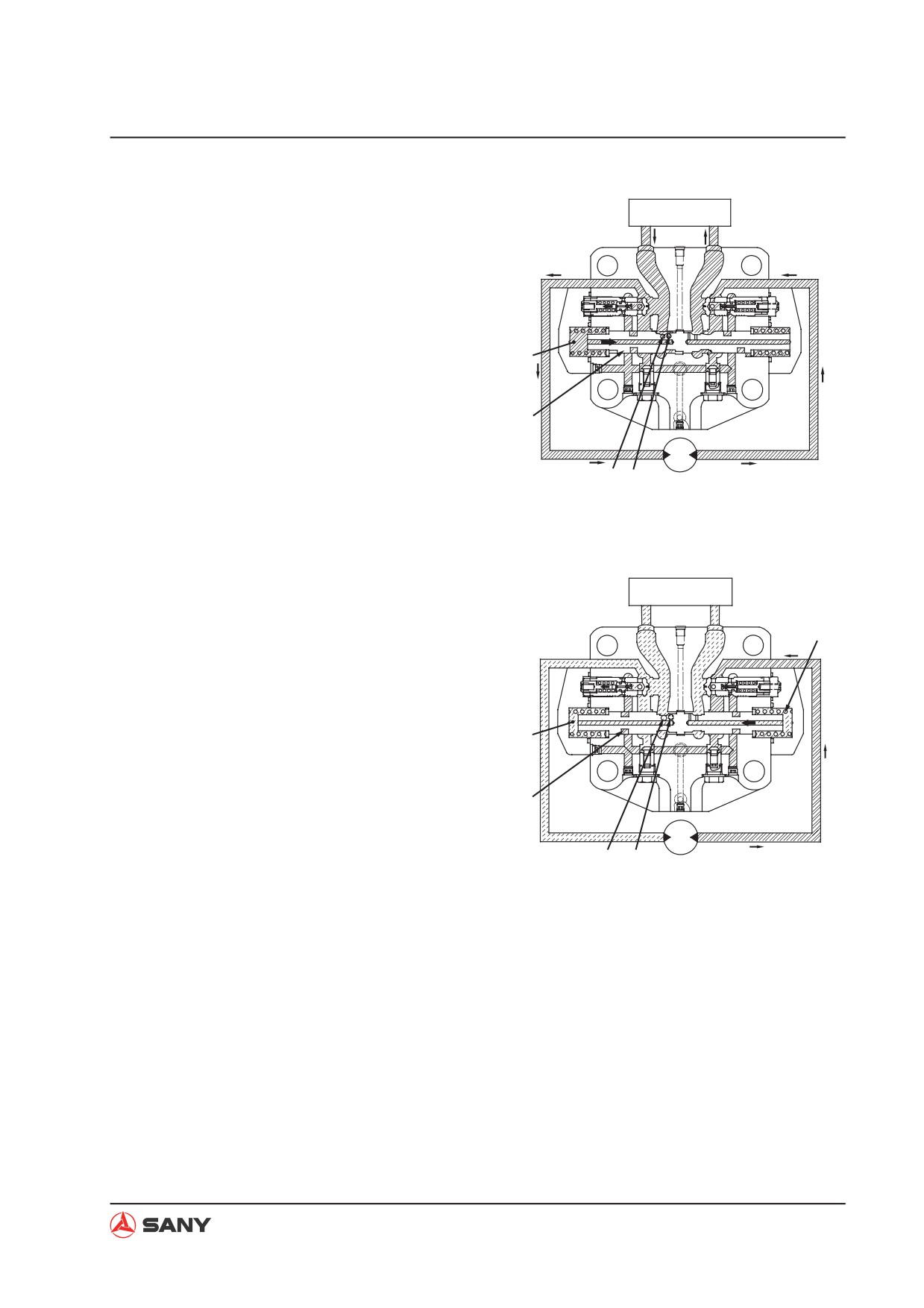
C. Counterbalance function
Ɣ When the engine runs at an excessively
high speed because of external force ap-
plied on it, the motor may lose control. At
this time, port P1 serves as the inlet side,
and the pressure drops. Pressure in spring
chamber 1 and damper chamber A1 also
drop. As a result, pison (1) moves to the
left under the force of spring (7-2), closing
circuit B. Circuit at the suction side is also
closed at the same time when the circuit
at return side is closed. When circuit B is
closed, pressure at port P1 rises due to
hydraulic oil from the main pump, moving
piston (10 to the right again. In this way,
when external load generates pump effect,
slight movement of piston (1) keep circuit
B open. The rotation speed of the motor
keeps in line with fuel supply of the main
pump, and the motor will not lose control
because of the vacuum in the hydraulic
system.
4-98
Structure and Function
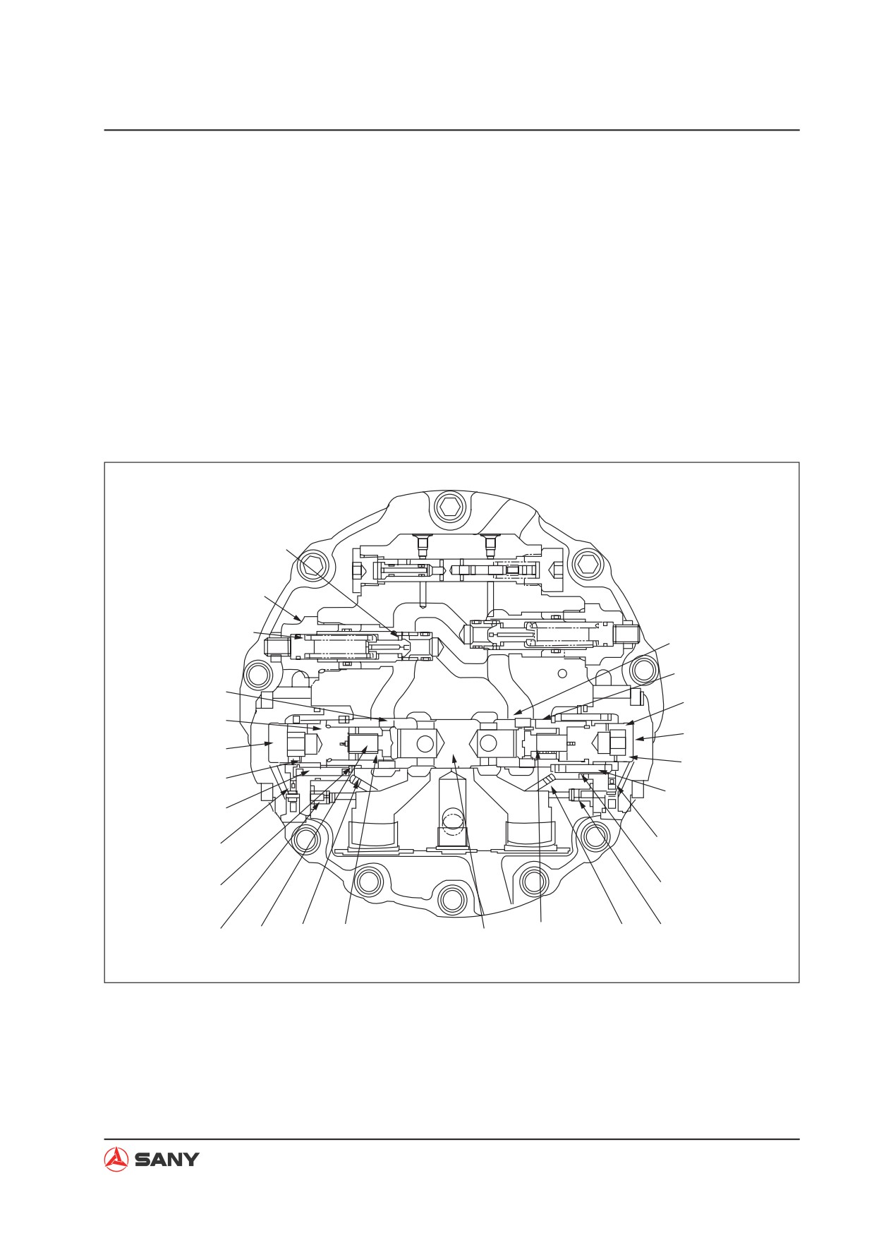
D. Braking of motor
Ɣ The counterbalance valve and the relief
braking force of motor rotation. When the
valve forms the braking circuit. When the
pressure at port M2 reaches the set pres-
main valve is neutralized position, hydrau-
sure of relief valve (8), cone valve (8-1) at
lic oil from the main pump is cut off, and
port M1 overcomes the force of spring (8-
pressure at port P1 and P2 is the same.
2) and moves to the left, and hydraulic oil
As a result, piston (1) moves to the neutral
flows the port M1. In this way, the impact-
position, and the opening area of circuit B
ing force due to inertia at port M2 is under
decreases. At the same time, because of
control, and vacuum at port M1 is avoided.
the inertia of external force, the motor does
not stop rotating (pump effect), and pres-
sure at port M2 rises and serves as the
8-1
8
8-2
Circuit B
Circuit C2
Circuit C1
M2
M1
Orifice D3
Orifice D1
Damper chamber A2
Damper chamber A1
Orifice D4
Orifice D2
Spring chamber 2
Spring chamber 1
P1
P2
6-1
6-2
7-1
7-2
5-1
3
4-1
2-1
1
2-2
4-2
5-2
ZX215-1002096
4-99
Structure and Function
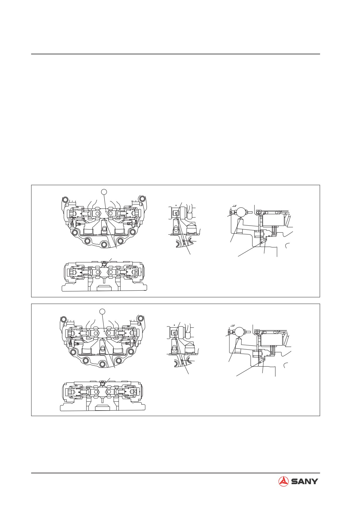
E. Shuttle valve function for high pressure
selection
Ɣ The counterbalance valve can function
ber E to release travel brake. In addition,
as a shuttle valve to release travel brake.
piston (1) moves to neutral position, as
When hydraulic oil is fed to port P1, piston
shown in fig 5 when motor stops. Circuit D
(1) moves to the right, as shown in fig. 4.
is closed and drain circuit F of motor body
At this time, drain circuit F of motor body
is connected. Hydraulic oil in travel brak-
is cut off, and circuit D leading to cylinder
ing cylinder chamber E is conducted to the
chamber E for travel braking is connected.
drain circuit of motor body, and travel brake
Hydraulic oil flows to circuit G via the ori-
is applied.
fice, and enters travel brake cylinder cham-
1
Circuit D
Circuit D
Orifice
Circuit F
Circuit F
Circuit D
Circuit G
Circuit G
Cylinder chamber E
ZX215-1002097
1
Circuit D
Circuit D
Orifice
Circuit F
Circuit F
Circuit D
Circuit G
Circuit G
Cylinder chamber E
ZX215-1002098
4-100
Structure and Function
Operation of parking brake
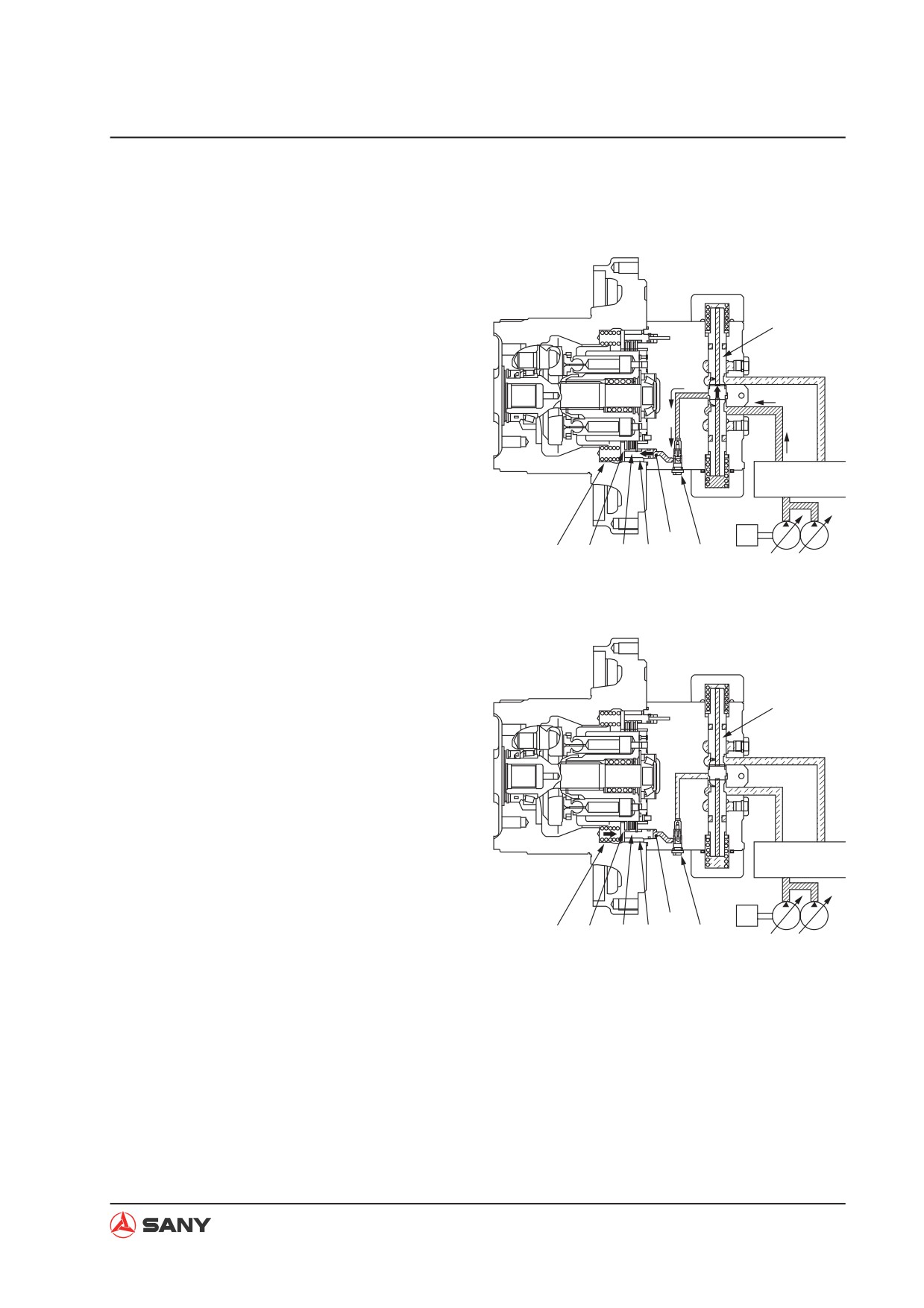
1) When travel begins
Ɣ As the travel lever is operated, pressurized
oil from the pump activates counterbalance
10
valve spool (10), opens the parking brake
circuit, and flows to chamber A of brake
piston (12). Pressurized oil overcomes the
force of spring (11) and pushes piston (12)
toward the left.
Ɣ Since the pushing force to plate (13) and
disc (14) disappears, plate (13) is sepa-
Travel control valve
rated from disc (14) and the brake is re-
leased.
M
A
11
14
13
12
22
ZX215-1002099
2) When travel stops
Ɣ As the travel lever is placed in neutral,
counterbalance valve spool (10) returns to
10
the neutral position and closes the park-
ing brake circuit. The pressurized oil in
chamber (A) of brake piston (12) passes
through the orifice of the brake piston and
is drained to the motor case. Brake piston
(12) is pushed to the right by spring (12).
Plate (13) and disc (14) are pushed to-
Travel control valve
gether, and the brake is applied. As brake
piston (12) returns, flow of pressurized oil
is reduced with slow return valve (22). The
M
A
time delay will be set to activate the brake
11
14
13
12
22
ZX215-1002100
only after the machine has stopped.
4-101
Structure and Function
Brake valve operation
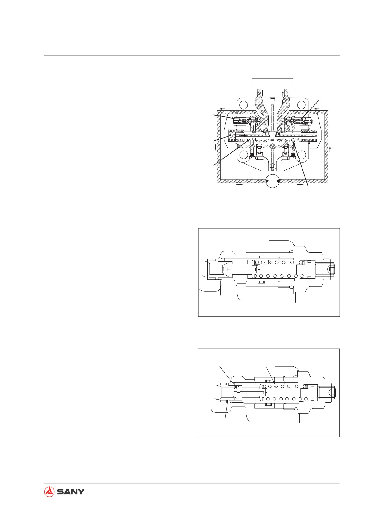
Ɣ The brake valve consists of suction safety
valve (8A) and counterbalance valve (18).
Travel control valve
Functions and operations of respective
PA
PB
components are described below.
8A
18
MA
MB
ZX215-1002101
1) Counterbalance valve and check valve
Function
Ɣ When the machine is travels downhill, the
weight of the machine tends to make the
Travel control valve
travel speed faster than the motor speed.
PA
PB
If the machine travels with the engine at
8B
low speed, the motor may rotate at zero
8A
load, resulting in run away and inviting a
very dangerous situation. These valves are
used to avoid such a situation by control-
ling the machine to travel as per the engine
speed (pump delivery).
19
MA
MB
Operation when pressurized oil is supplied
ZX215-1002102
Ɣ Operating the travel lever conducts the
pressurized oil from the control valve to
port (PA). The pressurized oil opens suc-
tion safety valve (8A) and then flows to
motor outlet port (MB) via motor inlet port
(MA). The motor outlet side is closed by
suction safety valve (8B) and spool (19),
so the pressure at the supply side rises.
4-102
Structure and Function
Ɣ The pressurized oil on the supply side
flows to chamber (S1) via orifice (E1) and
Travel control valve
orifice (E2) of the spool (19). As the pres-
PA
PB
sure in chamber (S1) goes above the spool
selector pressure, spool (19) is pushed
toward the right. Port (MB) and port (PB)
are connected, the motor outlet port side
opens and the motor starts rotating.
S1
19
MA MB
E1 E2
ZX215-1002103
Operation of brake during downhill travel
Ɣ If the machine goes out of control while
travelling downhill, the motor will be caused
Travel control valve
to rotate without load to decrease the inlet
PA
PB
side oil pressure. Pressure in chamber (S1)
20
is released via orifices (E1) and (E2). As
the pressure in chamber (S1) goes below
the spool selector pressure, spool (19)
is returned to the left by spring (20) and
S1
outlet port (MB) is throttled. The pressure
at the outlet port side rises, generating ro-
tation resistance on the motor to prevent
19
the machine from losing control. On the
other hand, the spool moves to a position
MA MB
where the pressure on outlet port (MB) can
E1
E2
be balanced against the machine's own
ZX215-1002104
weight and the inlet port pressure. Oil flow
from the outlet circuit is reduced to ensure
the travel speed corresponded to the pump
delivery.
4-103
Structure and Function
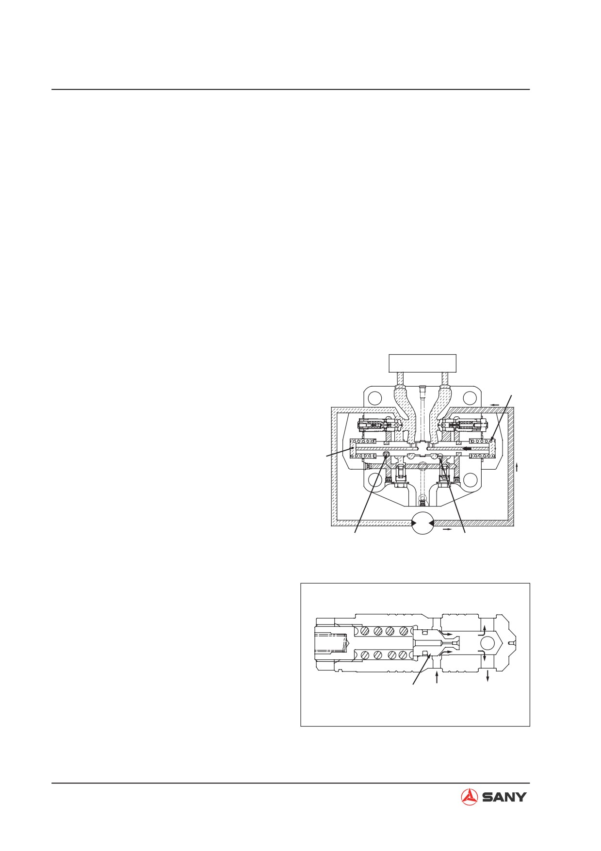
2) Safety valve
Function
Ɣ When the machine travel is stopped (or it
is travelling downhill), the counterbalance
valve closes the inlet and outlet circuits of
the motor. Since the motor is rotated by
inertial force, pressure in the motor outlet
port side is abnormally increased, poten-
tially resulting in damages on the motor
and piping. The safety valve releases this
abnormal pressure to the inlet port side of
the motor in order to prevent damages to
the equipment.
Operation
Travel control valve
1. When travel is stopped (or when travelling
PA
PB
downhill) (Right swing)
20
Ɣ Reduction of the pressure at motor inlet
(PA) decreases the pressure in chamber
(S1). When it drops beyond the spool
switching pressure, the spool is returned to
S1
the left by spring (20), reducing the pres-
sure at outlet passage (B1). At this time,
the motor continues rotating due to its iner-
tial force, thus pressure on the outlet port
MA MB
(MB) is increased.
A1
B1
ZX215-1002105
Ɣ When the pressure rises above the set
pressure of the suction safety valve (8A),
the poppet opens. The pressurized oil
passes through notch (A1) of spool (19)
into chamber (MA) of the circuit at the op-
posite side.
Spool MB
MA
ZX215-1002107
4-104
Structure and Function
2.
When starting travel (or when traveling at a
constant speed)
Travel control valve
PA
PB
8B
Ɣ
As the travel lever is operated, the pres-
surized oil from the pump moves spool (19)
8A
toward right. The passage to the suction
safety valve functions as a circuit which
passes through notch (B2) of spool (19),
S1
producing large differential pressure. The
pump pressure rises, providing a large
tractional force to the valve.
19
MA MB
E1
B2
ZX215-1002106
3) Relief valve
Ɣ
The structure of the relief valve is shown
in the right figure. This valve is area dif-
ference and direct flow type. It has impact
damping function during starting and brak-
ing.
ZX215-1002108
A. Operation principle and function
Ɣ When the main valve makes the motor
to start or brake, front pressure of cone
2-9-2
2-9-5
valve (2-9-2) rises above the set pressure
and the force of spring (2-9-5), and moves
cone valve (2-9-2) to the right and off the
valve seat. Pressurized oil in the front of
cone valve (2-9-2) is bypassed to the low
pressure side. The impact due to inertia
energy at the high pressure side is put un-
2-9-3
der control and vacuum is prevented from
ZX215-1002109
occurring at the low pressure side through
bypassing pressurized oil to the low pres-
sure side.
4-105
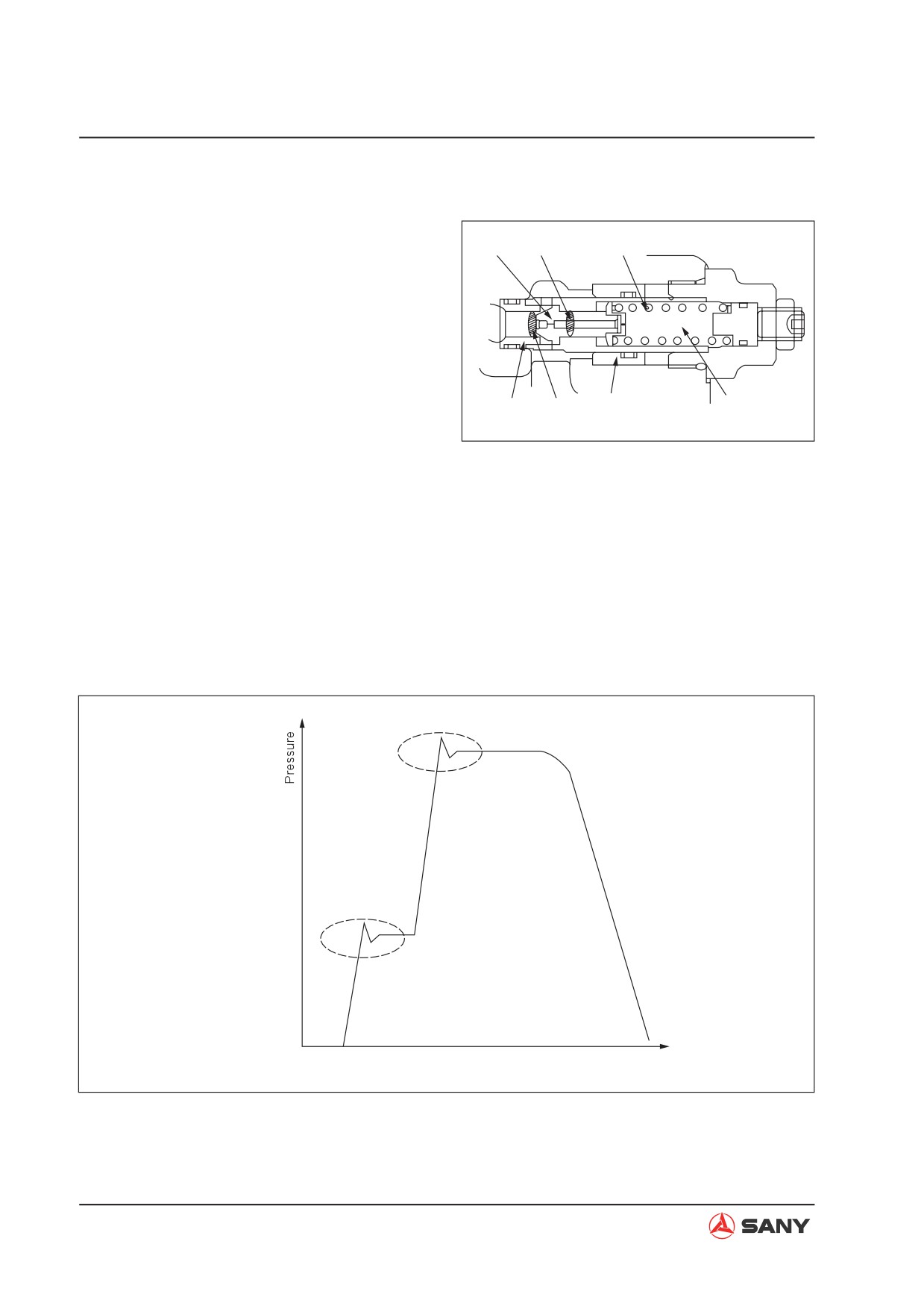
Structure and Function
B. Damping function
Ɣ When the relief valve begins to function,
damping piston (2-9-9) moves to the left.
2-9-2
Area S2
2-9-5
As a result, low pressure is maintained in
spring chamber D. At this time, the loaded
area of cone valve (2-9-2) is S1, and it is
much larger than the normal set loaded
area S1-S2 of the relief valve. So, when
damping piston (2-9-9) is moving, the func-
tional pressure of relief valve is maintained
2-9-3
Area S1
2-9-9
Spring chamber D
at 1/3 of normal set pressure in order to
ZX215-1002110
absorb the impact at the high pressure
circuit side due to inertia energy. When
the movement of damping piston stops,
pressure in spring chamber D rises. Pres-
sure at both side of cone valve (2-9-2) is
the same, and the relief valve is working at
normal set pressure. In this way, the relief
valve reduces the impact during motor start
and brake by a two-stage action to provide
excellent performance.
Damping method
Time
ZX215-1002111
4-106
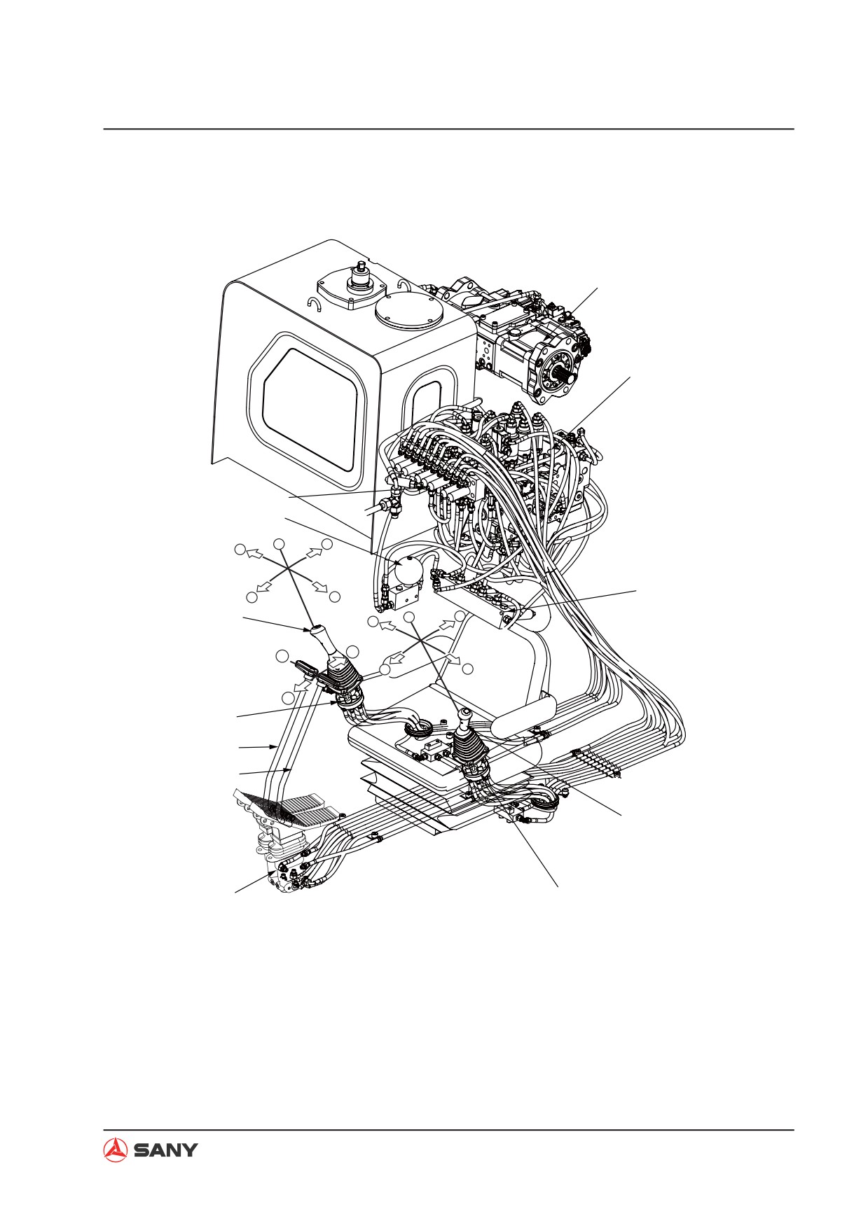
Structure and Function
4.6.7 Valve control system
8
9
7
6
1
2
4
10
3
5
5
6
7
9
12
11
8
10
13
4
3
2
11
1
12
ZX215-1002112
4-107
Structure and Function
Control lever position
1.
Travel PPC valve
(1) HOLD
2.
L. travel control lever
(2) Boom UP
3.
R. travel control lever
(3) Boom DOWN
4.
Right PPC valve
(4) Bucket DUMP
5.
Right joystick
(5) Bucket DIG
6.
Accumulator
(6) HOLD
7.
Transition block
(7) Arm IN
8.
Hydraulic pump
(8) Arm OUT
9.
Main control valve
(9) Right swing
10. Solenoid valve
(10) Left swing
11. Left joystick
(11) Neutral
12. Left PPC valve
(12) Reverse travel
(13) Forward travel
4-108
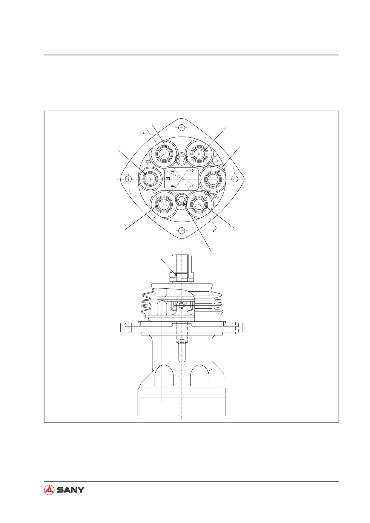
Structure and Function
4.6.8 Pilot valve
4.6.8.1 Work equipment and swing pilot valve
P3
P2
A
T
P
P1
P4
A
64~73.5Nm
19~22Nm
ZX215-1002113
P:
From pilot pump relief valve
P1:
L.H. Pilot valve: Arm OUT
R.H. Pilot valve: Boom DOWN
P2:
L.H. Pilot valve: Arm IN
R.H. Pilot valve: Boom UP
P3:
L.H. Pilot valve: Swing LEFT
R.H Pilot valve: Bucket DIG
P4:
L.H. Pilot valve: Swing RIGHT
R.H. Pilot valve: Bucket DUMP
T:
To tank
4-109