SANY Crawler Hydraulic Excavator (SY195C9, SY205C9, SY215C9, SY225C9). Shop Manual (2013) - page 8
Structure and Function
R
H
256-101
Aa
511
XAa2
XAa1
Ba
511
ZX225-1102013
4-50
Structure and Function
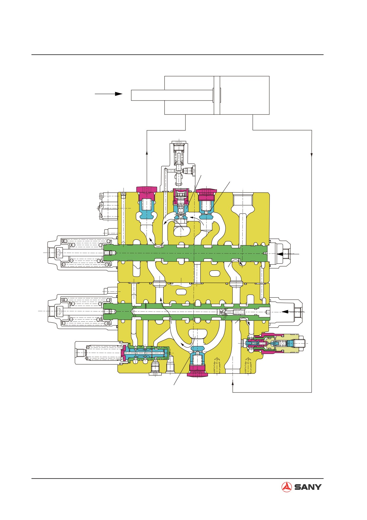
(2) Arm IN
[Pilot circuit]
from neutral bypass pushes open the cone
valve (511) of the check valve and flows
Ɣ When the arm 2 spool (306) is switched,
into the arm 2 spool (306) via the U pas-
the side path is closed and pressure at
sage. Then, it merges with port Ba via the
port Px (work equipment signal port) rises.
inner passage of arm 2 spool (306) and is
At the same time, pressure oil is supplied
supplied into the arm cylinder head end (H).
to port PaL and the release signal of lock
valve option set (252) is sent out.
Ɣ
On the other hand, pressure of the return
oil from the arm cylinder rod end (R) rises
[Main circuit]
under the weight the arm, and the return
oil returns to port Aa. Working oil that re-
Ɣ
When arm In is operated, pilot pressure oil
turns to port Aa flows into the inside of the
is supplied to port XBa1 and port XBa2.
valve spool via the holes on the periph-
When pilot pressure oil is applied at the
ery of the arm 1 spool (302), and pushes
two sides of port XBa1 and port XBa2,
open the cone valve (302-317) in the spool
arm 1 spool and arm 2 spool is switched to
only under light load. It merges with port
the left. As a result, working oil from P2 is
Ba through the holes on the spool. This is
introduced into the neutral bypass (2) via
called the regeneration function of the arm.
main passage (3). Neutral bypass is cut off
by switching arm 1 spool (302). Therefore,
Ɣ
If the pressure at the arm cylinder head
working oil flown into the parallel passage
end and in the U passage rises, arm re-
pushes open the cone valve (511) of the
generation check valve spool (257-211)
check valve and flows into the arm 1 spool
switches to the left. And, at the same time,
(302) via the U passage. Then, it flows into
the back pressure of the cone valve (302-
the periphery of arm 1 spool (302) and is
317) in the spool is closed. Therefore,
supplied into the arm cylinder head end (H)
arm regeneration function is released and
via port Ba.
return oil from the arm cylinder rod end
(R) flows into the spool via the hole (a) on
Ɣ
On the one hand, working oil from port P1
the periphery of arm 1 spool (302). Then,
is introduced into neutral bypass (2) via
it flows into arm regeneration check valve
main passage (1). Neutral bypass is cut off
set (257) via hole (c) on the periphery of
by switching the arm 2 spool (306). There-
arm 1 spool (302), and returns to the work-
fore, working oil in the parallel passage
ing oil tank via tank port R1.
pushes open the logic cone valve (256-101)
of the arm 2 logic valve GP, and working oil
4-51
Structure and Function
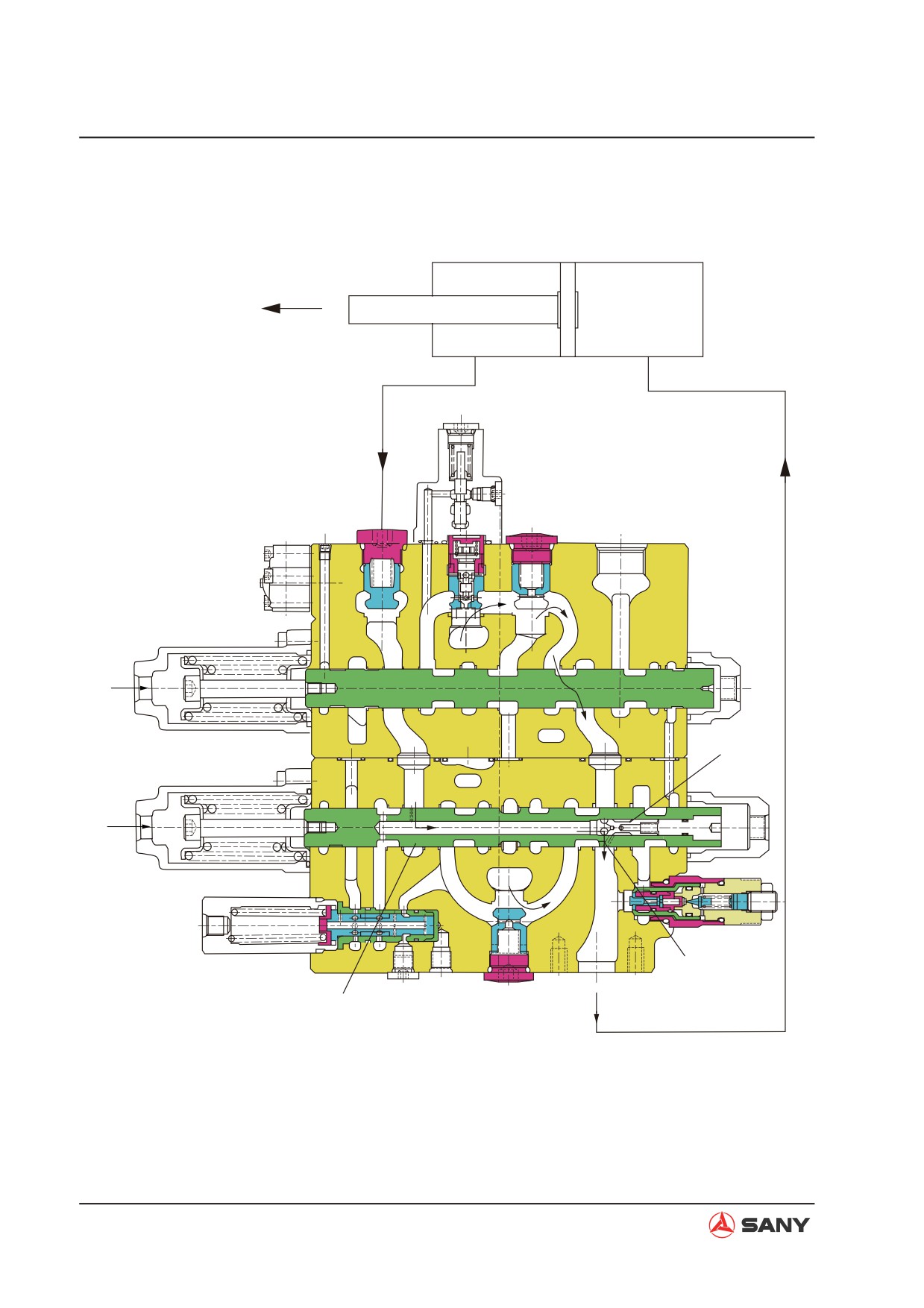
Ɣ Light load
Arm weight
R
H
Aa
XBa2
(302-317)
XBa1
(b)
(a)
Ba
ZX225-1102014
4-52
Structure and Function
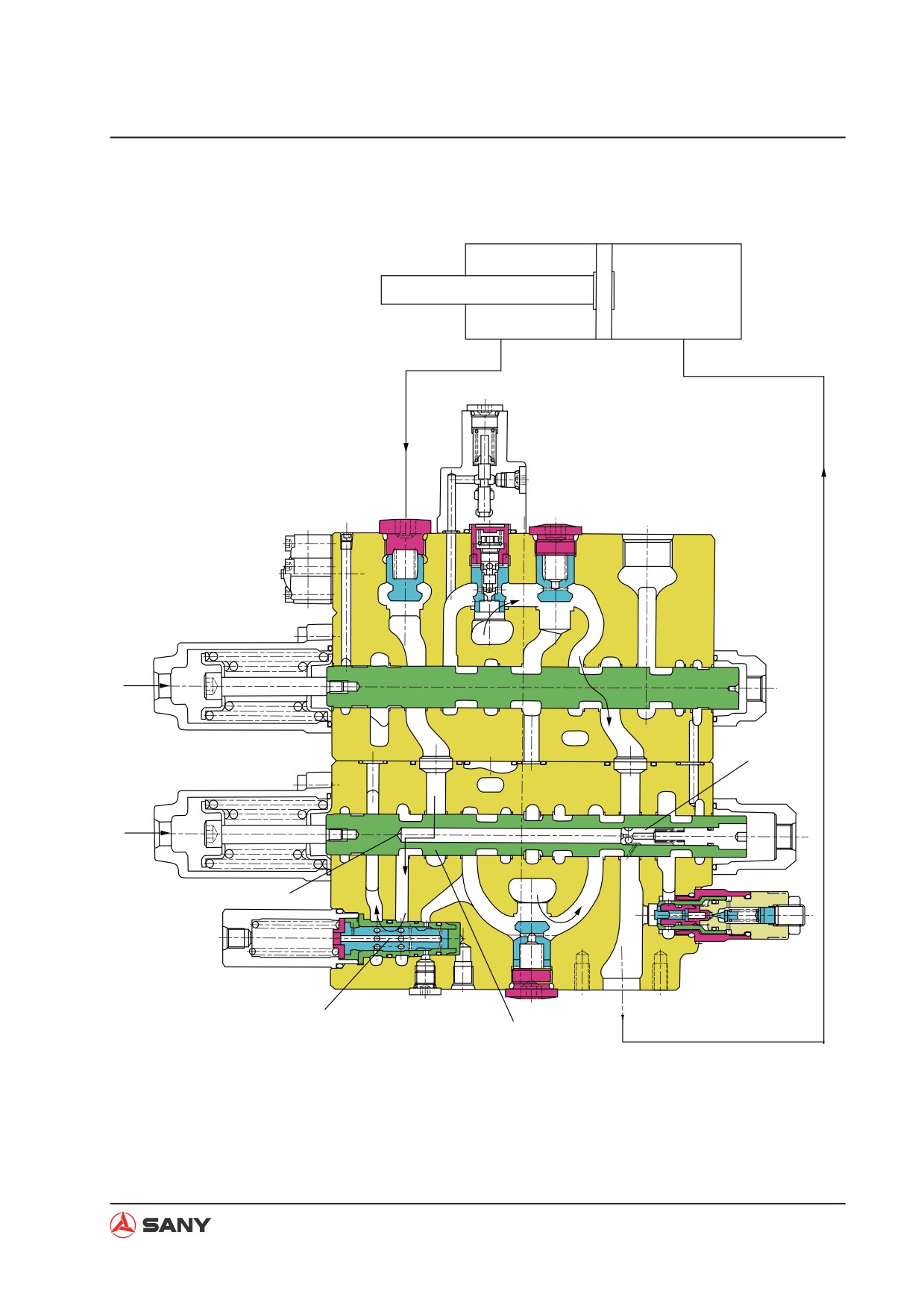
Ɣ When pressure at arm cylinder head end (H) rises
R
H
Aa
XBa2
(302-317)
XBa1
(c)
(257-211)
Ba
(a)
ZX225-1102015
4-53
Structure and Function
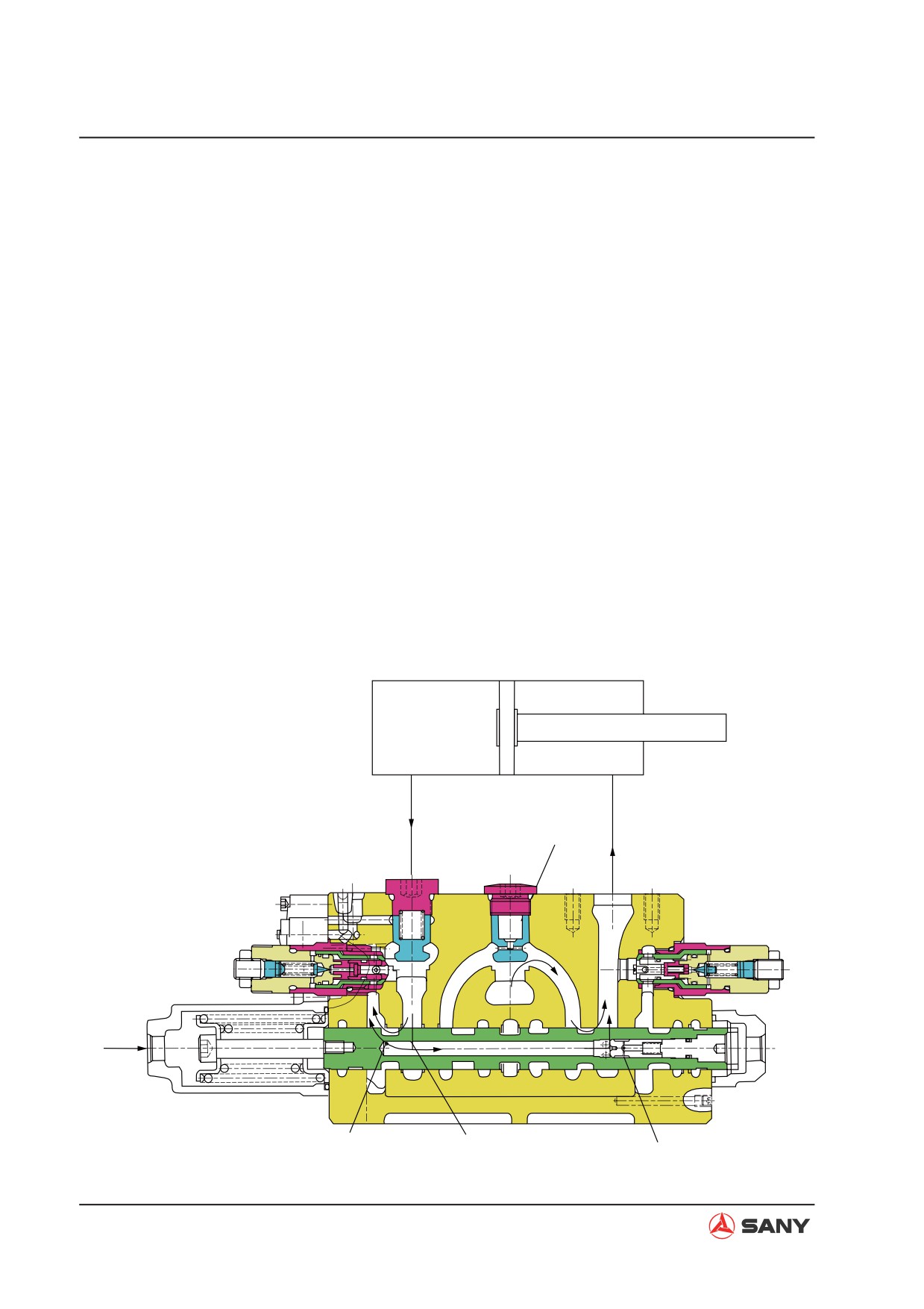
4.5.2.4 Boom
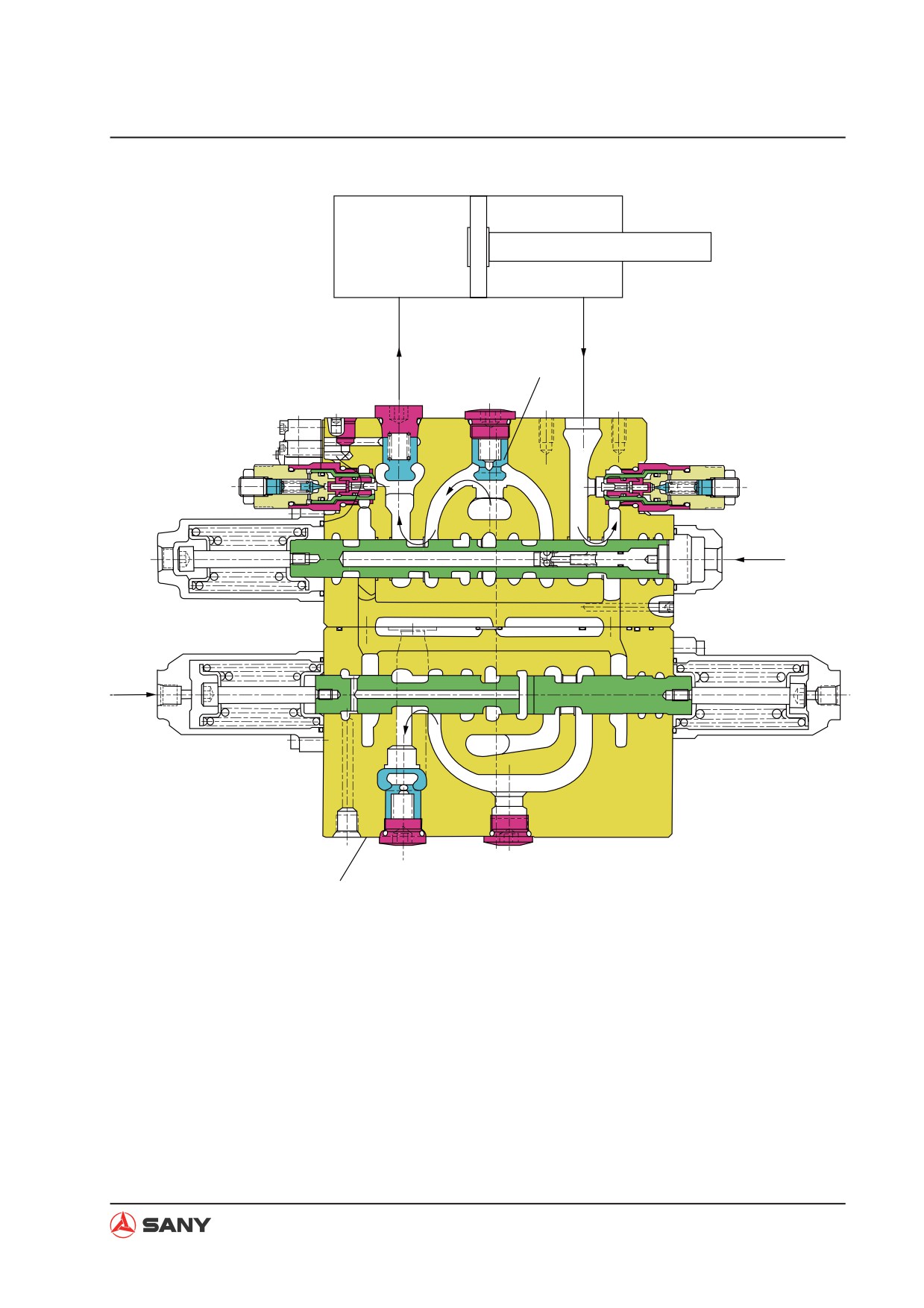
(1) Boom UP
[Pilot circuit]
Ɣ
At the same time, pilot pressure oil is also
supplied to port XAb2 and boom 2 spool
Ɣ When the boom 1 spool (303) is switched,
(307) moves to the right. Working oil from
the side path is closed and pressure at port
port P2 is introduced into neutral bypass.
Px (work equipment signal port) rises.
Neutral bypass is cut off by switching the
boom 2 spool (307). Therefore, working
[Main circuit]
oil in the parallel passage flows into boom
Ɣ When boom UP is operated, pilot pressure
2 spool (307) via the U passage. Then, it
oil is supplied into port XAb1 and boom 1
pushes open the cone valve (511) of the
spool (303) moves to the left. Working oil
check valve and merges with port Ab and
from port P1 is introduced into neutral by-
is supplied into the boom cylinder head
pass (2) via main passage (1). Neutral by-
end (H). This is called the boom conflu-
pass is cut off by switching boom 1 spool
ence function.
(303). Therefore, working oil in the parallel
Ɣ
On the other hand, return oil from the
passage pushes open the cone valve (511)
boom cylinder rod end (H) via port Bb flows
of the check valve, and flows into the boom
into the periphery of boom 1 spool (303)
1 spool (303) via the U passage. Then, it
and returns to the working oil tank via tank
flows into the periphery of boom 1 spool
port (R1).
(303) and is supplied into the boom cylin-
der head end (H) via port Ab.
4-54
Structure and Function
H
R
511
Ab
Bb
XAb1
XAb2
511
ZX225-1102016
4-55
Structure and Function
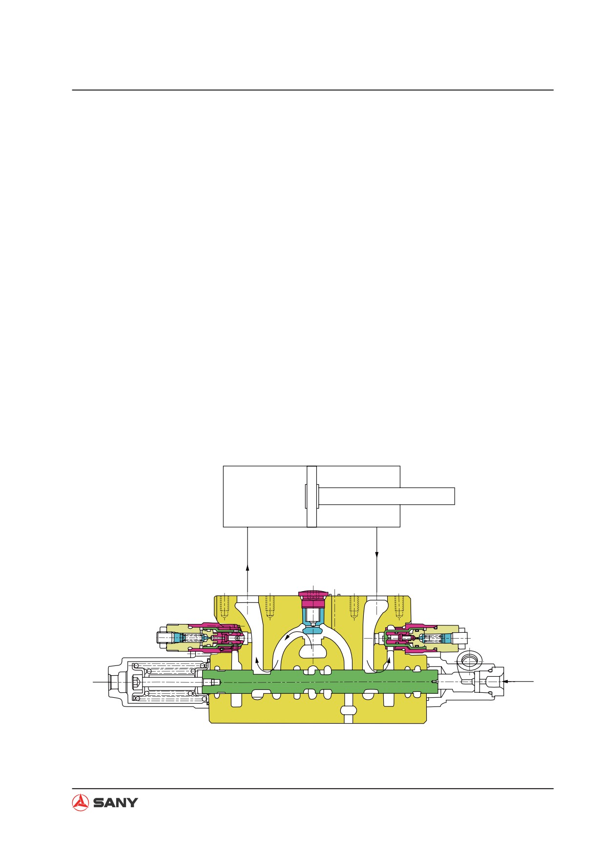
(2) Boom DOWN
[Pilot circuit]
passage. Then, it flows into the periphery
of boom 1 spool (303) and is supplied into
Ɣ When the boom 1 spool (303) is switched,
the boom cylinder rod end (R) via port Bb.
the side path is closed and pressure at
port Px (work equipment signal port) rises.
Ɣ On the other hand, return oil from the
At the same time, pressure oil is supplied
boom cylinder head end (H) passes the
to port PbL and the release signal of lock
hole (a) and the periphery of boom 1 spool
valve option set (252) is sent out.
(303).
[Main circuit]
Ɣ Return oil pressure rises due to the self
weight of the boom. Cone valve (303-317)
Ɣ When boom DOWN is operated, pilot pres-
in the spool is pushed to the right. Return
sure oil is supplied to port XBb1. Boom 1
oil flows to the outside of spool. The pres-
spool (303) moves to the right. As a result,
sure oil is supplied into the boom cylinder
working oil from P1 is introduced into the
rod end (R) as the working oil for boom
neutral bypass (2) via main passage (1).
DOWN operation. This is called the boom
Neutral bypass is cut off by switching boom
regeneration function. Part of the oil that
1 spool (303). Therefore, working oil flown
flows into the inside passage of the spool
into the parallel passage pushes open the
via hole (a) returns to the working oil tank
cone valve (511) of the check valve and
via hole (b).
flows into the boom 1 spool (303) via the U
H
R
511
Ab
Bb
XBb1
(b)
(a)
(303-317)
ZX225-1102017
4-56
Structure and Function
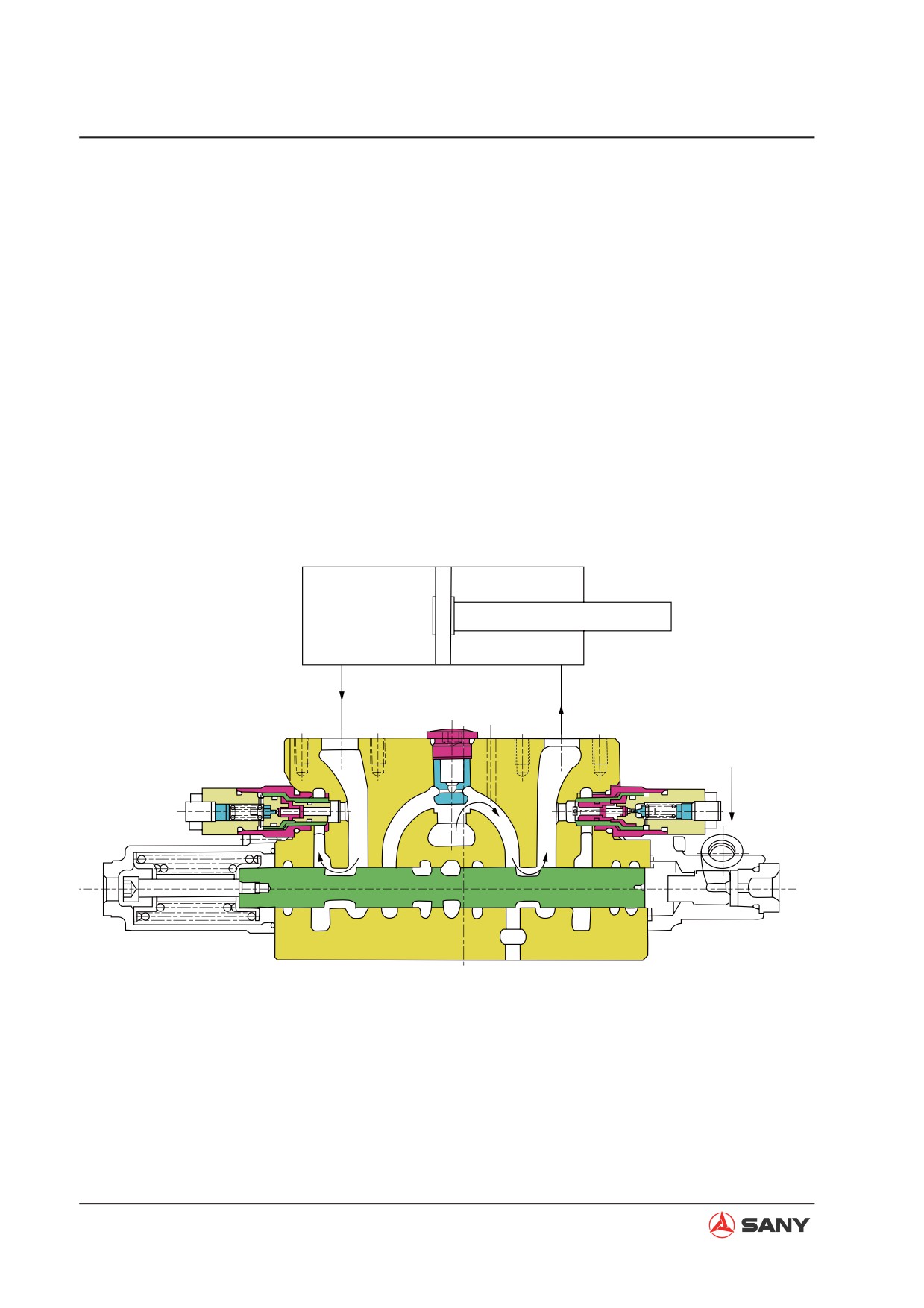
4.5.2.5 Bucket
(1) Bucket DIG
[Pilot circuit]
Then, it flows into the periphery of bucket
spool (304) and is supplied into the bucket
Ɣ When the bucket spool (304) is switched,
cylinder head end (H) via port Ak.
the side path is closed and pressure at port
Px (work equipment signal port) rises. At
Ɣ On the other hand, return oil from the buck-
the same time, pressure oil is supplied at
et cylinder rod end (R) flows in via port Bk.
port XBp2.
Then, it flows to oil tank port (R1) via the
spool periphery and returns to working oil
[Main circuit]
tank.
Ɣ When bucket DIG is operated, pilot pres-
Ɣ When boom UP and bucket DIG are oper-
sure oil is supplied into port XAk and buck-
ated simultaneously, pilot pressure oil is
et spool (304) moves to the right. Working
supplied to port Pck. Therefore, the stroke
oil from port P1 is introduced into neutral
of bucket spool is not limited at stroke end,
bypass (2) via main passage (1). Neutral
but on any position halfway. As a result,
bypass is cut off by switching bucket spool
bucket cylinder passage is throttled and
(304). Therefore, working oil in the paral-
working oil flows into boom 1 spool (303)
lel passage pushes open the cone valve
via bucket spool (304). In this way, boom
(511) of the check valve, and flows into
UP operation takes precedence.
the bucket spool (304) via the U passage.
H
R
Ak
Bk
H
XAk
Pck
ZX225-1102018
4-57
Structure and Function
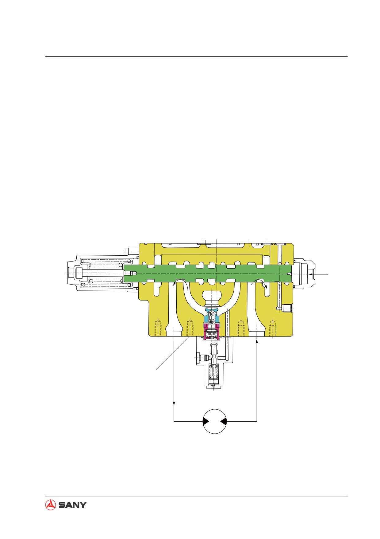
(2) Bucket DUMP
[Pilot circuit]
tral bypass is cut off by switching bucket
spool (304). Therefore, working oil in the
Ɣ When the bucket spool (304) is switched,
parallel passage pushes open the cone
the side path is closed and pressure at port
valve (511) of the check valve, and flows
Px (work equipment signal port) rises. At
into the bucket spool (304) via the U pas-
the same time, pressure oil is supplied at
sage. Then, it flows into the periphery of
port XBp2.
bucket spool (304) and is supplied into the
bucket cylinder rod end (R) via port Bk.
[Main circuit]
Ɣ On the other hand, return oil from the buck-
Ɣ When bucket DUMP is operated, pilot
et cylinder head end (H) flows in via port
pressure oil is supplied into port XBk and
Ak. Then, it flows to oil tank port (R1) via
bucket spool (304) moves to the left. Work-
the spool periphery and returns to working
ing oil from port P1 is introduced into neu-
oil tank.
tral bypass (2) via main passage (1). Neu-
R
H
Ak
Bk
XBk
ZX225-1102019
(3) Bucket confluence
Ɣ When bucket DIG is operated, pilot pres-
switching neutral bypass valve spool (310).
sure oil is supplied into port XBp2 and the
Therefore, working oil pushes open the
neutral bypass cutoff valve spool (310) is
check valve, and interconnects with the U
switched. Working oil from port P2 is in-
passage via the inside path, and converg-
troduced into neutral bypass (2) via main
es with bucket spool (304).
passage (3). Neutral bypass is cut off by
4-58
Structure and Function
4.5.2.6 Swing
(1) Swing operation
[Pilot circuit]
(305). Therefore, working oil in the parallel
passage pushes open the logic cone valve
Ɣ When the swing spool (305) is switched,
(2540-101) of the swing logic valve GP,
the side path is closed and pressure at port
and flows into the swing spool (305) via the
Px (work equipment signal port) rises.
U passage. Then, it flows into the periph-
ery of swing spool (305) and is supplied
[Main circuit]
into the swing motor via port As (or Bs).
Ɣ When swing is operated, pilot pressure
Ɣ On the other hand, return oil from the
oil is supplied into port XAs (or XBs) and
swing motor flows in via port Bs (or port
swing spool (305) is switched. Working
As). Then, it flows into tank port (R1) via
oil from port P2 is introduced into neutral
the spool periphery and returns to the
bypass (2) via main passage (3). Neutral
working oil tank.
bypass is cut off by switching swing spool
XBs
XAs
As
Bs
(254-101)
Swing motor
ZX225-1102020
4-59
Structure and Function
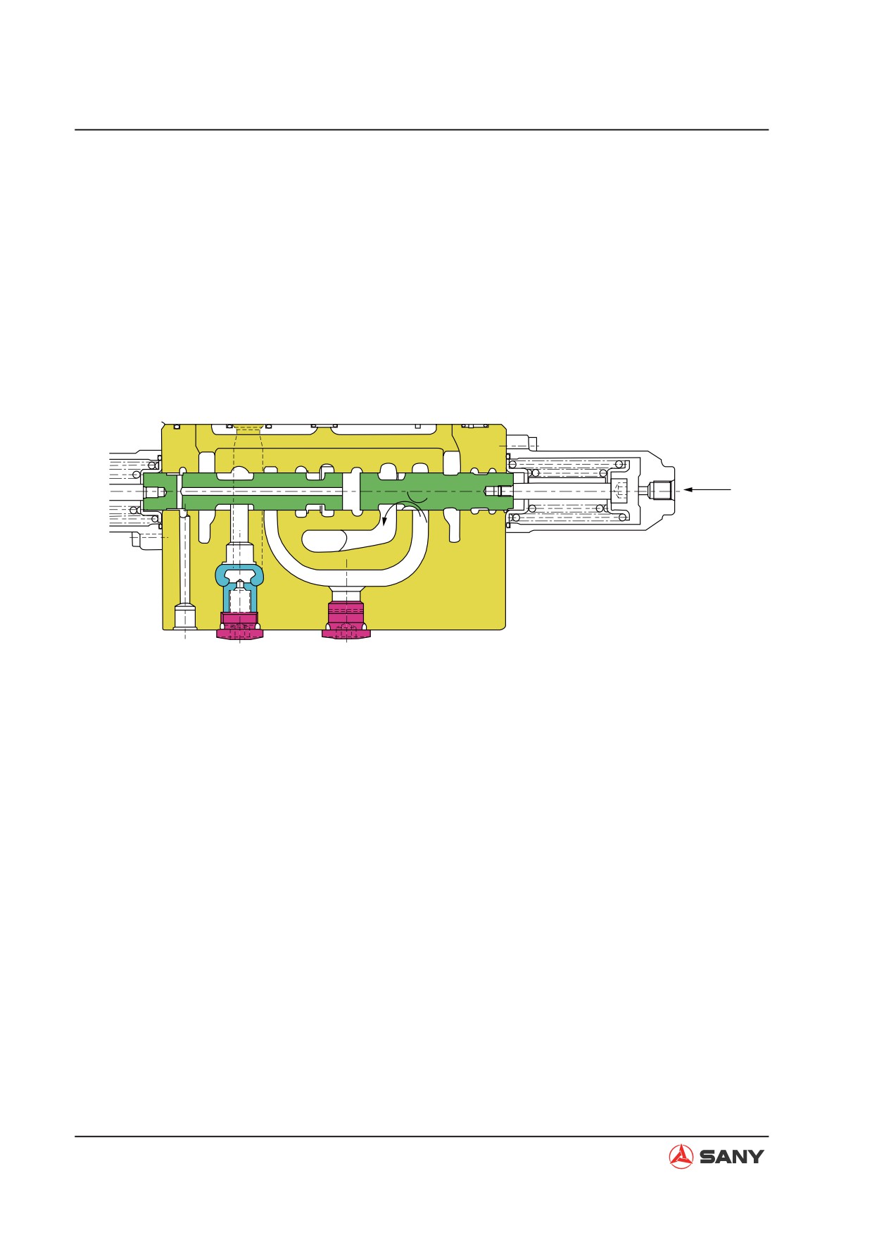
(2) Swing priority function
[Pilot circuit]
Ɣ Switch swing priority spool (311). The
opening area of the swing priority reduces.
Ɣ Pilot pressure oil is supplied to port Psp
As a result, working oil from arm 1 spool
and swing priority spool (311) is switch.
(302) flows into swing spool (305) and
swing operation takes precedence.
[Main circuit]
Psp
ZX225-1102021
4-60
Structure and Function
4.5.2.7 Option
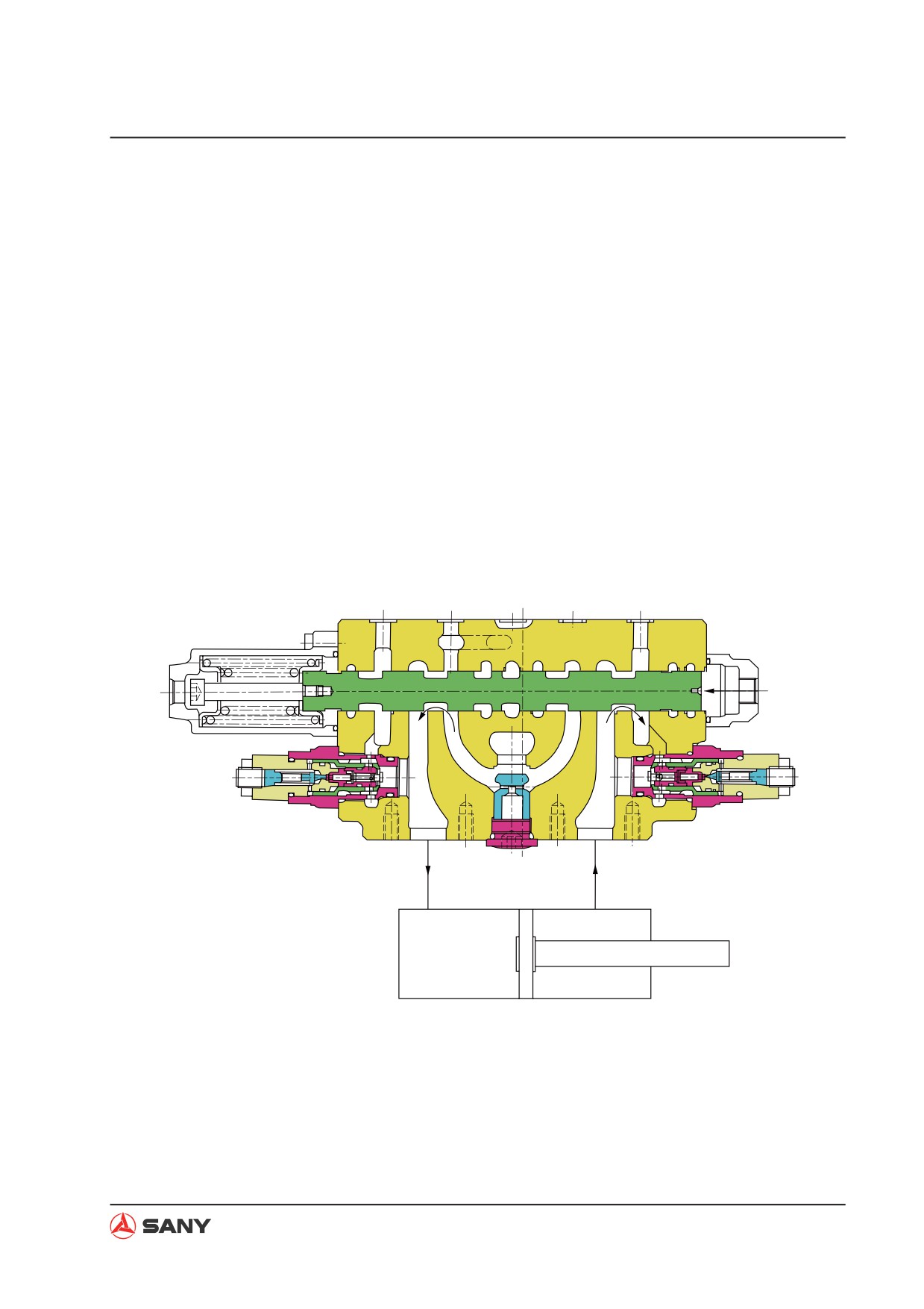
Option spool is used to control optional work equipment attachment.
(1) Operation
[Pilot circuit]
(309). Therefore, working oil in the parallel
passage pushes open the cone valve (511)
Ɣ When the option spool (309) is switched,
of the check valve, and flows into the op-
the side path is closed and pressure at port
tion spool (309) via the U passage. Then,
Px (work equipment signal port) rises.
it flows into the periphery of option spool
(309) and is supplied into the optional
[Main circuit]
equipment via port Ao (or Bo).
Ɣ When option is operated, pilot pressure
oil is supplied into port XAo (or XBo) and
Ɣ On the other hand, return oil from the op-
option spool (309) is switched. Working
tional equipment flows in via port Bo (or
oil from port P2 is introduced into neutral
port Ao). Then, it flows into tank port (R1)
bypass (2) via main passage (3). Neutral
via the spool periphery and returns to the
bypass is cut off by switching option spool
working oil tank.
XAo
XBo
Ao
Bo
ZX225-1102022
(2) Option confluence
Neutral bypass is cut off by switching by-
pass valve spool (310). Therefore, work-
Ɣ To achieve option confluence, pilot pres-
ing oil pushes open the cone valve (514)
sure oil is supplied into port XBp1 and the
of check valve, and converges with option
bypass cutoff valve spool (310) is switched.
spool (309) via the inside path and the U
Working oil from port P1 is introduced into
passage.
neutral bypass (2) via main passage (1).
4-61
Structure and Function
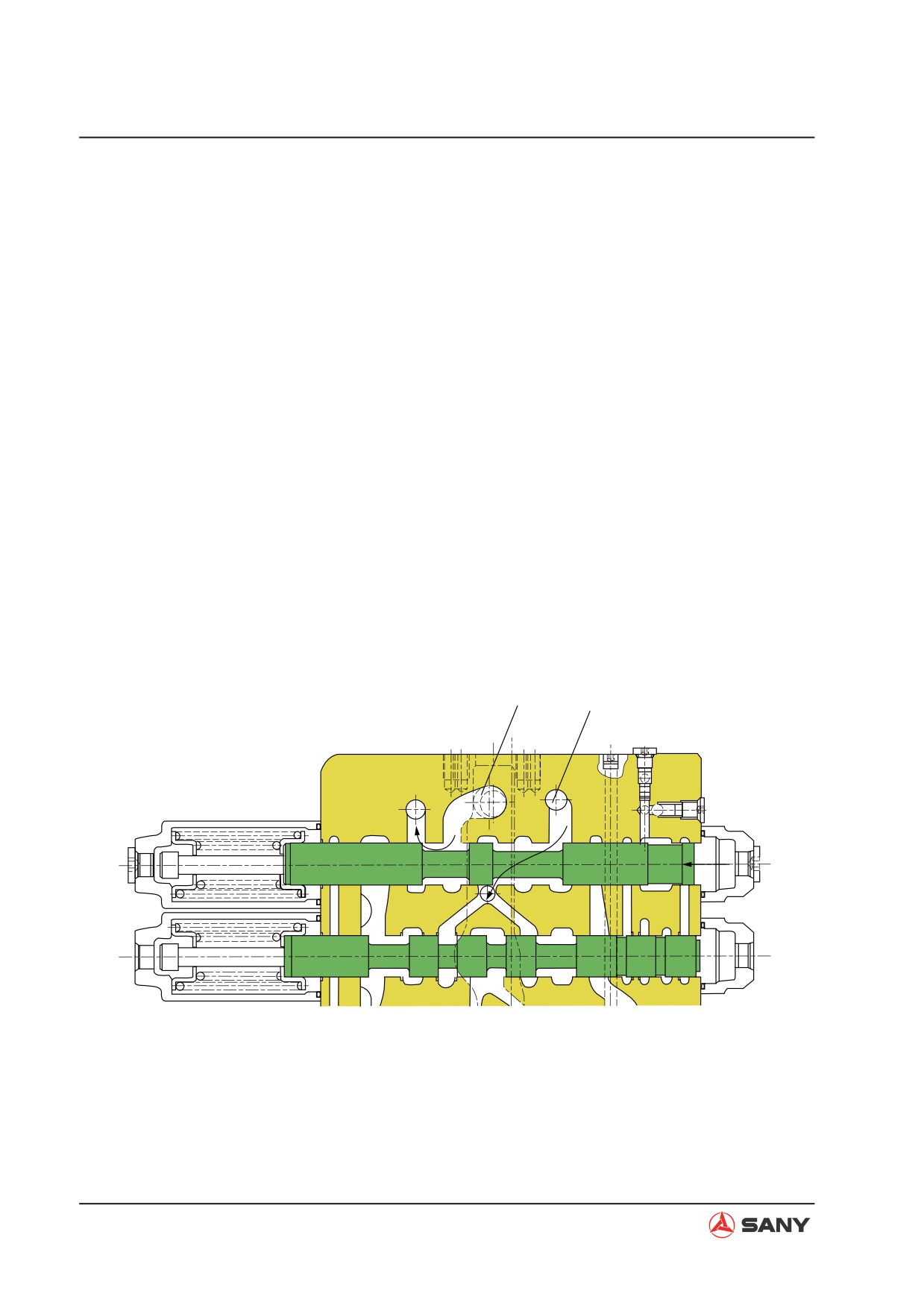
4.5.2.8 Travel straight
When travel spool (301) and other spool are
[Main circuit]
operated simultaneously.
Ɣ When straight travel spool (308) is
The following case shows when travel spool
switched, the right/left travel spool (301)
(301) and swing spool (305) are operated si-
are interconnected with port P2. The paral-
multaneously. (When pilot pressure oil is sup-
lel passage of swing/boom 2/option/arm
plied to port XAtL, port XAtr and port Xas)
1 circuit and boom 1/bucket/arm 2 circuit
are interconnected with port P1. Therefore,
[Pilot circuit]
working oil supplied from port P2 flows into
port Atl and port Atr, and is supplied to the
Ɣ The side path of right/left travel spool (301)
two travel motors equally.
and the side path of the swing spool (305)
at the downflow side are closed.
Ɣ On the other hand, working oil from port P1
is supplied to the swing motor via port As.
Ɣ Pilot oil from port PG is supplied to port
PTa and straight travel spool (308) is
Ɣ When oil pressure at port P2 is lower than
switched.
that at port P1, part of the working oil form
port P1 is supplied to port P2. In this way,
sharp decrease of travel speed is averted.
P1
P2
PTa
ZX225-1102023
4-62
Structure and Function
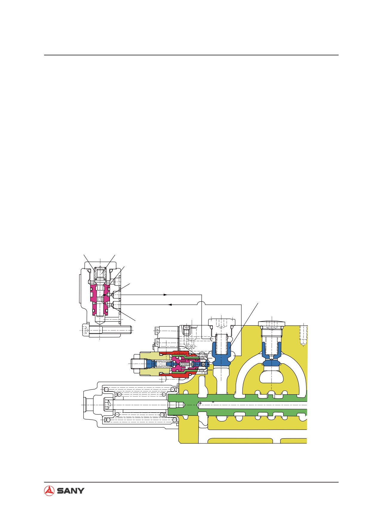
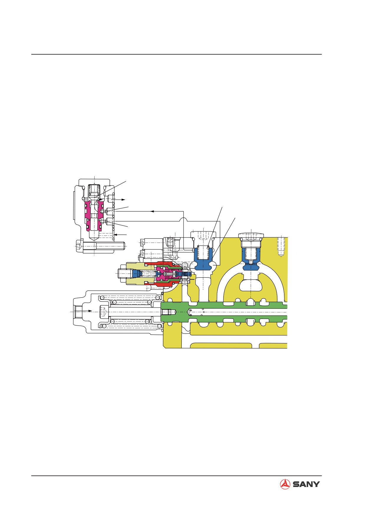
4.5.2.9 Lock valve function
Ɣ The lock valve option set (252) is installed
Ɣ When boom 1 spool (303) is in neutral po-
between the arm cylinder rod end (R) and
sition, spool (252-511) in the lock valve op-
arm 2 spool (302) and arm 2 spool (306).
tion set is pressed against the valve seat
It is used to reduce the internal leakage of
of the valve sleeve (252-541) inside the
the spool due to cylinder pressure.
lock valve option set, as shown in the illus-
tration, via the spring force of spring (252-
Ɣ Likewise, lockout option set (252) is also
321).
installed between boom cylinder head end
(H) and boom 2 spool (303) to reduce the
Ɣ At this position, working oil at the boom
internal leakage of he spool due to cylinder
cylinder head end (H) flows in via hole (a)
pressure.
and flows out from hole (b) through the
periphery of the lock valve option set spool
(1) Spool in neutral position
(252-511), pressing the cone valve (513)
against the valve seat of the valve block
Ɣ The following shows when boom 1 spool
via hole (b). By this means, oil leakage is
(303) is in neutral position. (The same is
reduced.
with arm 2 spool (306))
252-321
252-511
252-541
(b)
513
(a)
ZX225-1102024
4-63
Structure and Function
(2) Boom DOWN operation
Ɣ When boom DOWN is operated, pilot pres-
into spring chamber (RH). In addition, oil
sure oil is supplied to port PbL and port
in the spring chamber (RH) flows into drain
XBb1. Spool (252-511) inside the lock
circuit via hole (b). In this way, the cone
valve option set moves to the top by via pi-
valve (513) is pushed up by the pressure
lot pressure oil. Through the movement of
at boom cylinder head end (H) and the
spool (252-511) inside the lock valve option
function of the lock valve option set (252)
set, hole (a) is cutoff and working oil from
is released.
boom cylinder head end (H) does not flow
252-511
(b)
(RH)
513
(a)
PbL
XBb
ZX225-1102025
(2) Boom UP operation
Ɣ When boom DOWN is operated, pilot pres-
boom 1 spool (303) and working oil flows
sure oil is supplied to port XAb1. The cone
into port Ab.
valve (513) is pushed ope by the oil from
4-64
Structure and Function
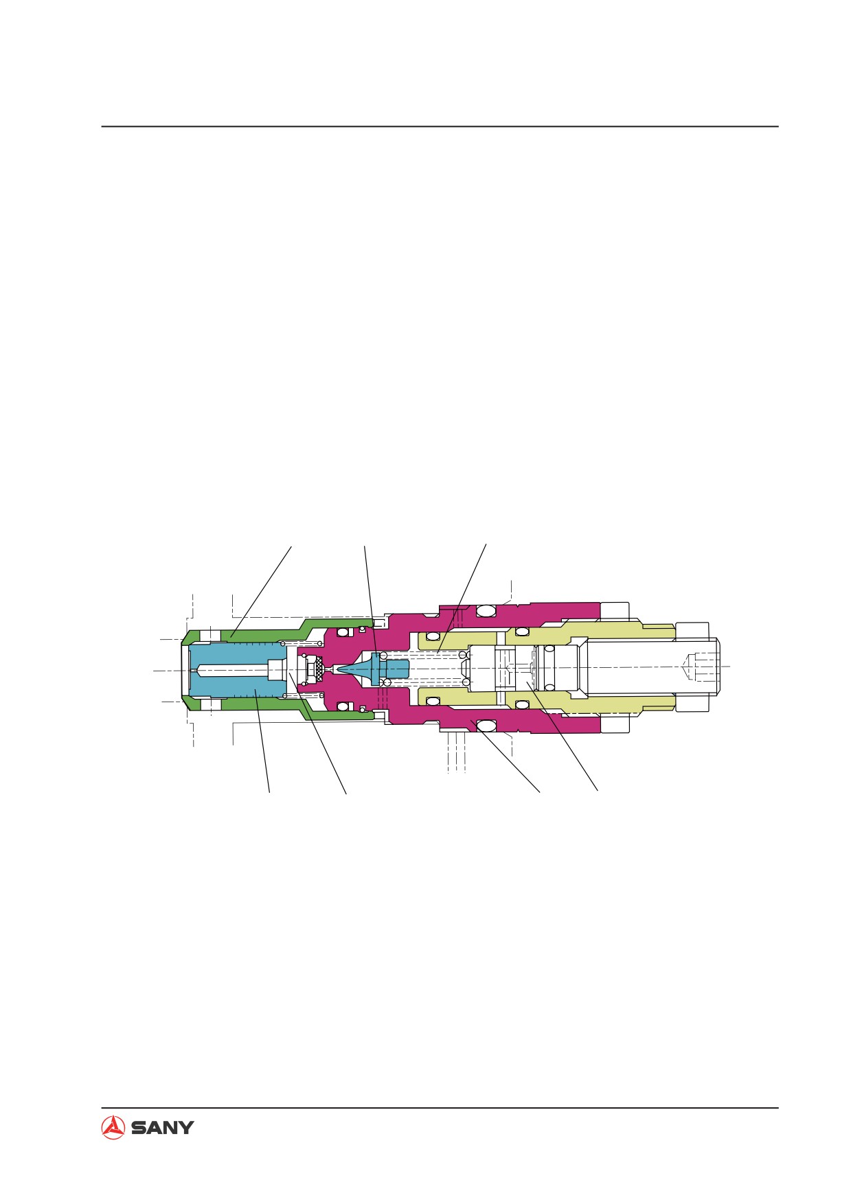
4.5.2.10 Main relief valve function
The main relief valve is installed on the valve
and enters low-pressure path (R).
block A (101). Its function is described below:
Ɣ Opening of cone valve (611) causes pres-
Ɣ Working oil flows into chamber (a) from
sure in chamber (a) to drop and valve rod
passage (P) via the hole of valve seat (541)
(512) is open. In this way, working oil in
and hole on valve rod (512). Valve rod (512)
passage (P) flows into low-pressure path
is pressed against valve seat (541), form-
(R) directly.
ing a tight seal.
Ɣ When pressure oil high than 3MPa is sup-
Ɣ When pressure in passage (P) exceeds
plied to port Pz, this pressure oil pushes
the elastic force of spring (621), cone valve
plunger (614) to the left. The set load of
(611) is pushed open. Therefore, working
spring (621) is changed and pressure of
oil flows through the hole on valve sleeve
the main relief valve rises.
(103) via the periphery of cone valve (611)
541
611
621
P
R
Pz
512
(a)
103
614
ZX225-1102026
4-65
Structure and Function
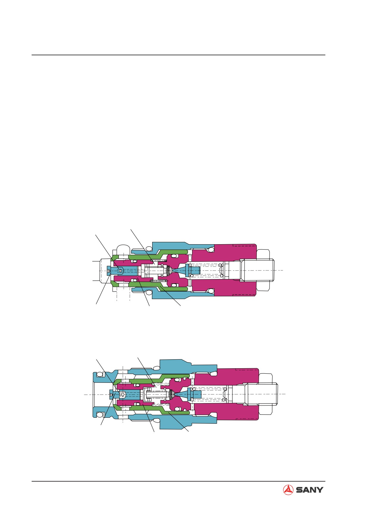
4.5.2.11 Port relief valve function
The port relief valve is installed between the
tank port and low-pressure path. In addition
to the function as relief valve, it has also the
function of anti-cavitation oil complement
check valve. Its function is described below:
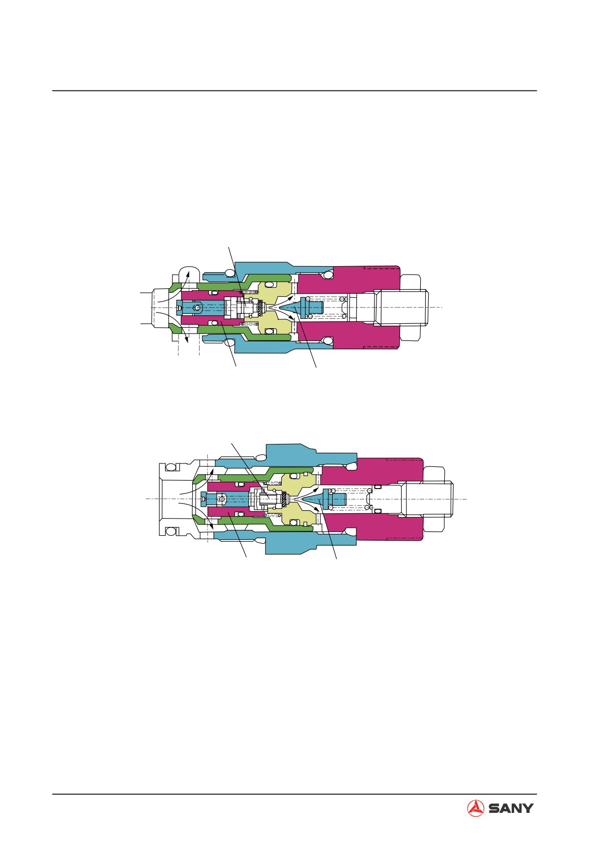
(1) Relief valve function
Ɣ Working oil flows into chamber (B) via the
hole (A) on plunger (301). Valve rod (511)
is pressed against valve seat (541), and
valve seat (541) is pressed onto the valve
seat of the valve block, forming a tight seal.
B
A
P
R
301
511
541
ZX225-1102027
A
B
P
R
301
511
541
ZX225-1102028
4-66
Structure and Function
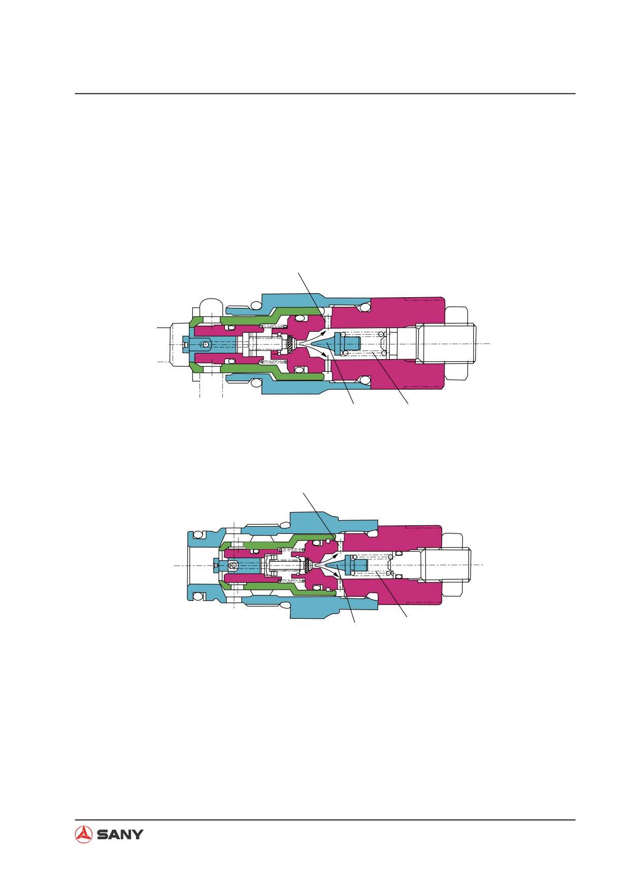
Ɣ When pressure in passage (P) exceeds
the elastic force of spring (621), cone valve
(611) is pushed open. Therefore, working
oil flows through hole (C) via the periphery
of cone valve (611) and enters low-pres-
sure path (R).
C
P
R
611
621
ZX225-1102029
C
P
R
621
611
ZX225-1102030
4-67
Structure and Function
Ɣ Opening of cone valve (611) causes pres-
sure in chamber (B) to drop and valve rod
(511) is open. In this way, working oil in
passage (P) flows into low-pressure path
(R) directly.
B
P
R
511
611
ZX225-1102031
B
P
R
511
611
ZX225-1102032
4-68
Structure and Function
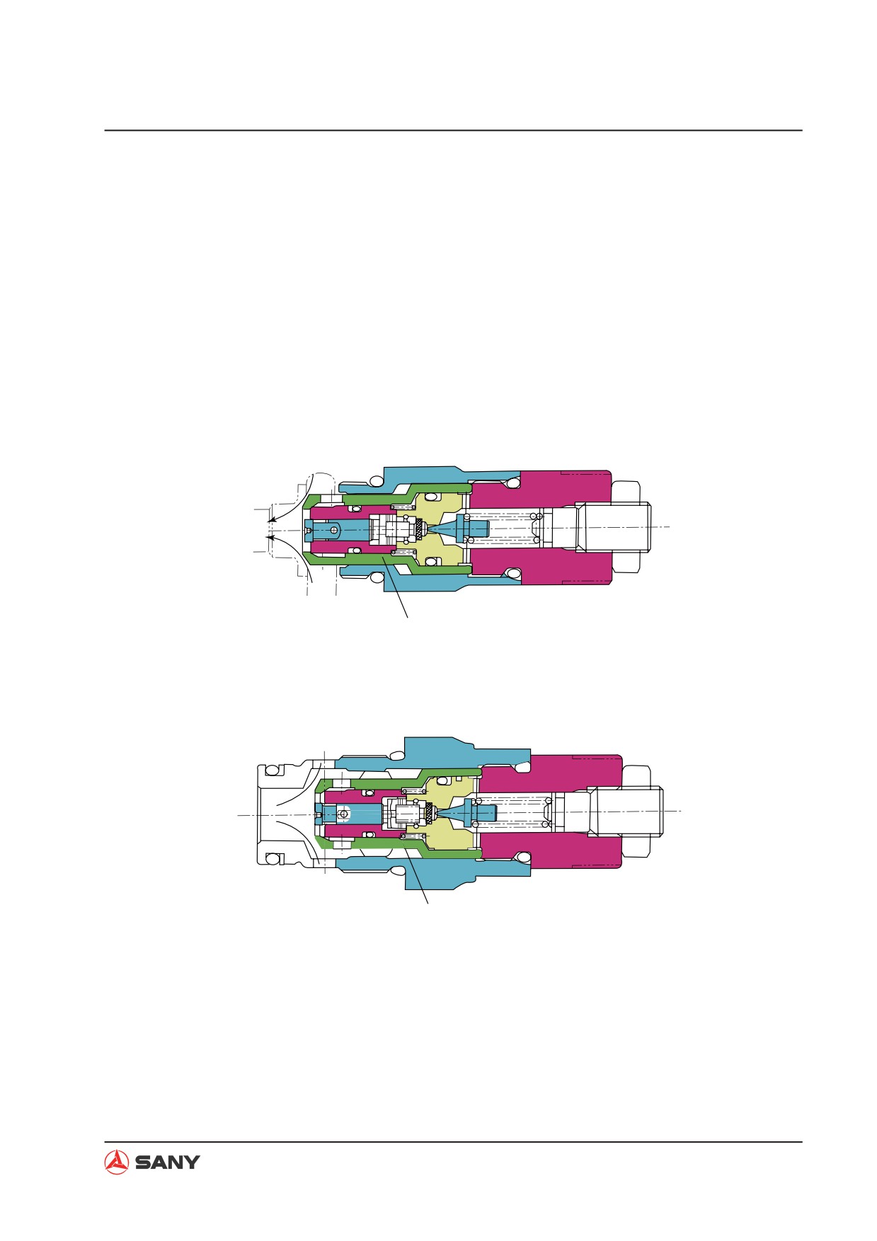
(2) Anti-cavitation oil complement check
valve
Ɣ When negative pressure is formed in path
(P), working oil is supplied from path (R).
When pressure in path (R) gets higher
than pressure in path (P), valve seat (541)
moves to the right direction. Therefore,
working oil is supplied from path (R) to
path (P) via the periphery of valve seat
(541) in order to prevent cavitation.
P
R
541
ZX225-1102033
P
R
541
ZX225-1102034
4-69