Motovario: Motoreducers, Motovariators, Electric Motors. Product catalog - page 12
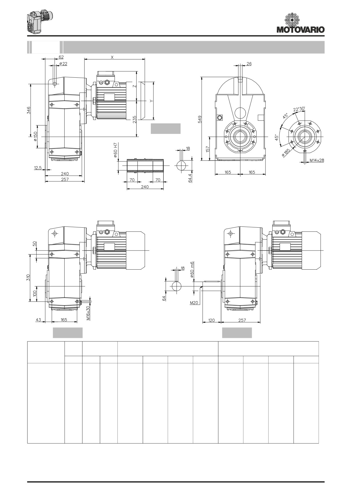
122/..3
Dimensioni / Dimensions / Abmessungen / Encombrements / Dimensiones
CS
CS...C
CS...D
Motore normale / Standard motor / Normaler Motor /
Motore autofrenante / Brake motor / Bremsmotor
IS
PAM
Moteur normal / Motor normal
Moteur frein / Motor-freno
125
~Kg
A
~Kg
X
Y
Z
~Kg
X
Y
Z
~Kg
80
61
82
-
-
-
-
-
-
-
-
90s
61
82
267
173
130
91
343
173
130
96.5
90l
61
82
292
173
130
92
368
173
130
97.5
100
76
84.2
326
191
139
98
407
191
139
103.5
112
76
84.2
347
211
154
108
443
211
154
117.7
132s
91.8
101
87
386
249
194
123
485
249
194
133.3
132m
101
87
434
249
194
132
537
249
194
146.7
160s
148
93
540
310
244
-
-
-
-
-
160l
148
93
584
310
244
-
-
-
-
-
180
148
93
641
349
260
-
-
-
-
-
200
185
108
-
-
-
-
-
-
-
-
Per le dimensioni relative alla zona attacco motore (Pm, Dm, bm, tm) fare riferimento alla tabella di pag. 223.
For the dimensions concerning the motor connection area (Pm, Dm, bm, tm) please refer to the table shown at page 223.
Zu den Abmessungen des Motoranschlußflansches (Pm, Dm, bm, tm) siehe Tabelle auf Seite 223.
Pour les dimensions concernant la zone de montage du moteur (Pm, Dm, bm, tm) lire SVP le tableau à la page 223.
Para las magnitudes correspondientes a la zona del motor (Pm, Dm, bm, tm) consulte la tabla de la página 223.
220
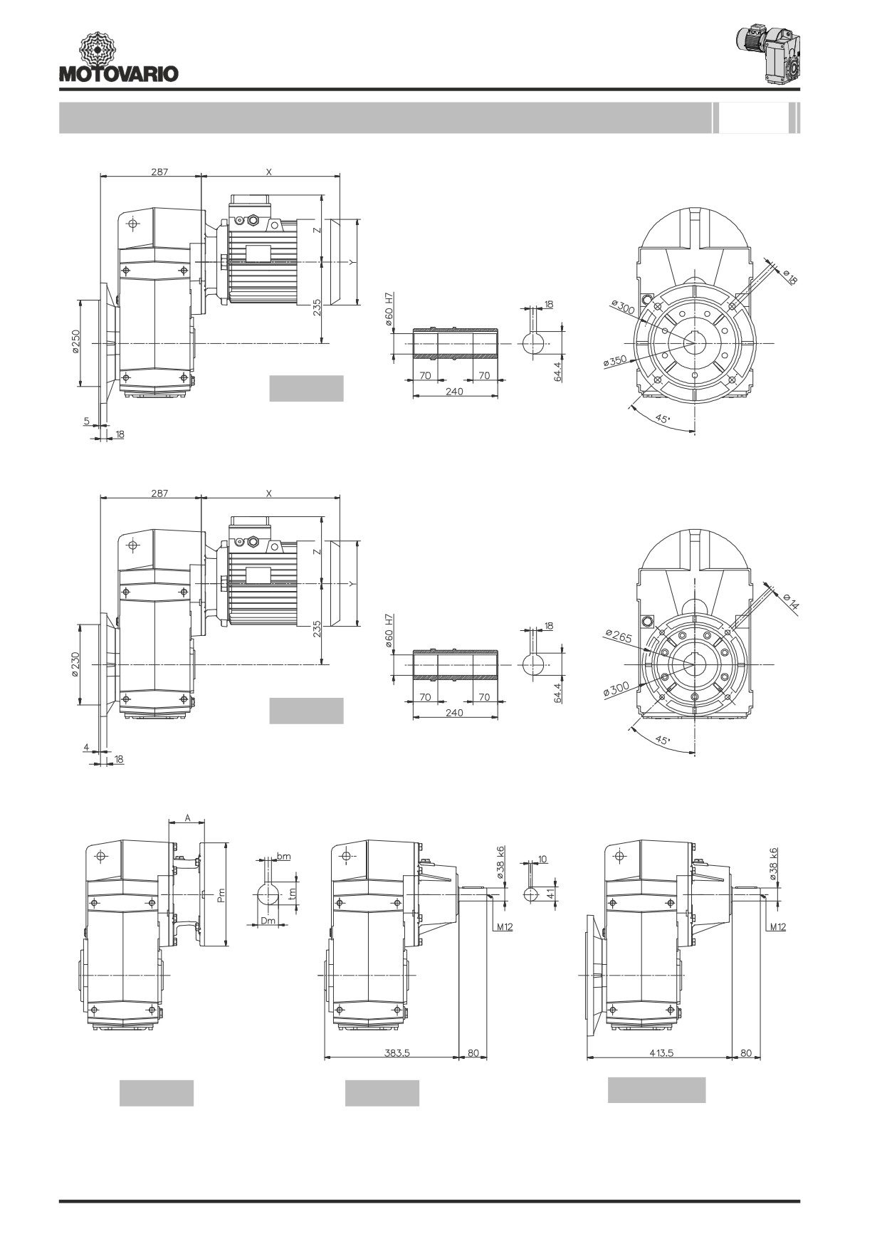
Dimensioni / Dimensions / Abmessungen / Encombrements / Dimensiones
122/..3
CS...FB
CS...FC
S...C
IS...C
IS...FB - FC
221
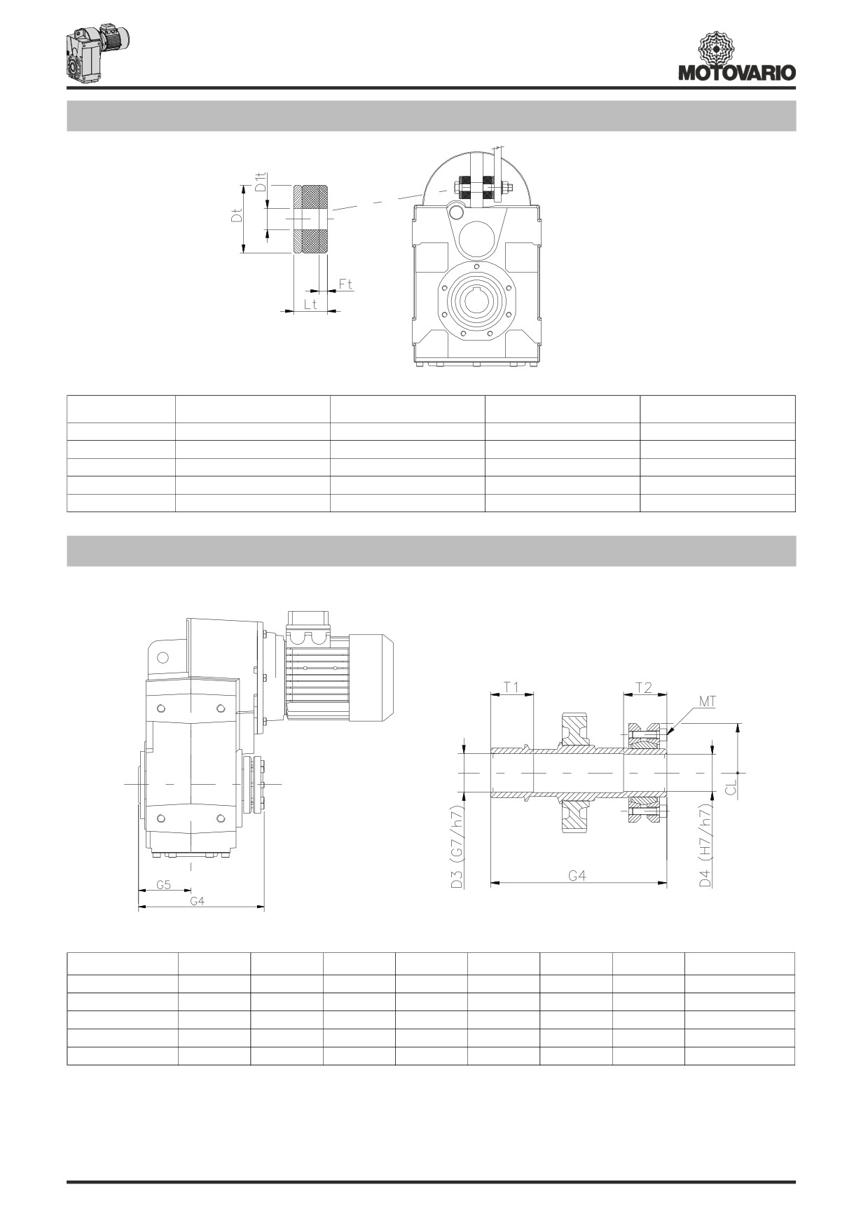
Braccio di reazione / Torque arm / Drehmomentstütze / Bras de réaction / Brazo de reacción
Dt
D1t
Lt
Ft
050
40
12,5
20
~ 3
060
40
12,5
20
~ 3
080
40
12,5
20
~ 3
100
60
21
30
~ 5
125
60
21
30
~ 5
Calettatore / Shrink disc / Schrumpfscheibe / Frette d’accouplement / Aro de apriete
D3
D4
G4
G5
T1
T2
CL
MT 12.9 (Nm)
050
31
30
152
60
35
35
74
15
060
36
35
173
70
40
35
80
15
080
41
40
217
90
50
40
100
15
100
51
50
248
105
55
40
115
15
125
61
60
282
120
60
50
145
40
- Pulire e sgrassare le zone degli alberi interessati all’accoppiamento. Rispettare la coppia di serraggio viti indicata (MT).
- Clean and degrease the surfaces of the shaft to be fitted to. Comply with the indicated tightening torque of screws (MT).
- Vor Montage der Schrumpfscheibe den Außendurchmesser der Hohlwelle reinigen und entfetten. Die Schrauben (MT) mit dem vorgeschriebenen
Drehmoment anziehen.
- Nettoyer et dégraisser les surfaces des arbres intéressés par l’acouplement. Respecter le couple de serrage des vis indiqué (MT).
- Pulir y desengrasar las partes interessadas en el acoplamiento. Observar el par de torsion de los tornillos indicados (MT).
222
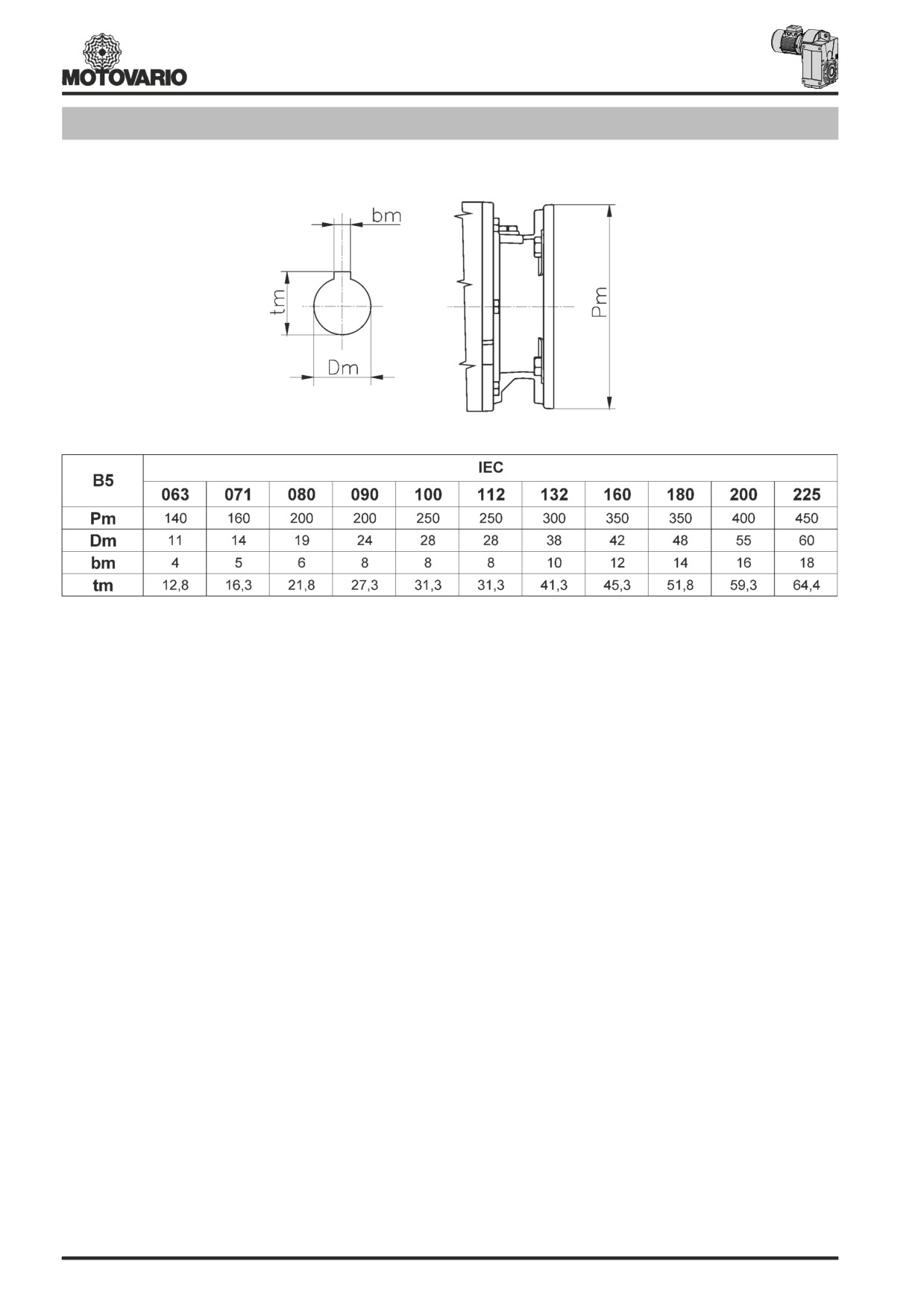
PAM B5 - Dimensioni / Dimensions / Abmessungen / Encombrements / Dimensiones
223

Note / Notes / Aufzeichnung / Notes / Notas
224
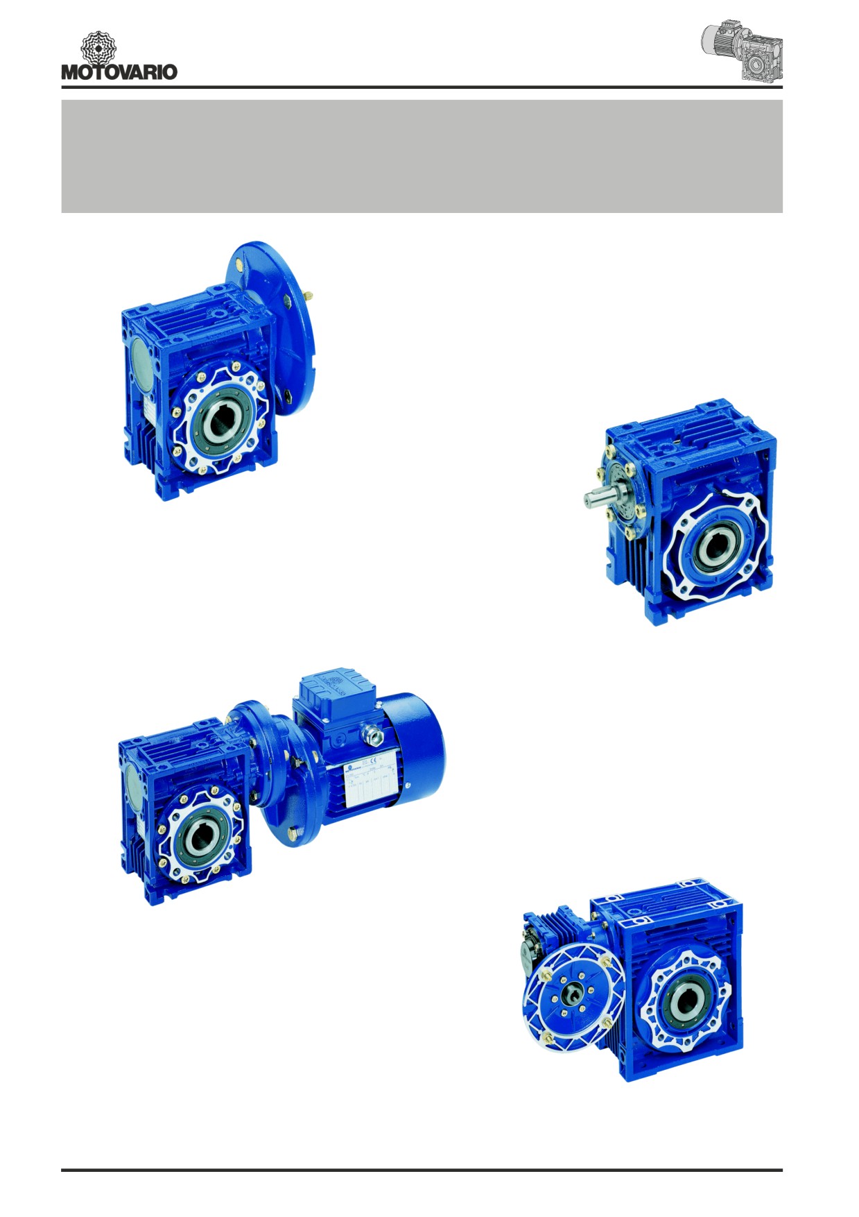
Motoriduttori e riduttori a vite senza fine
Worm geared motors and worm gear units
Schneckengetriebemotoren und Schneckengetriebe
NMRV
Motoréducteurs et réducteurs à vis sans fin
Motorreductores y reductores de tornillo sinfin
NMRV
NRV
PC+NMRV
NMRV+NMRV
225

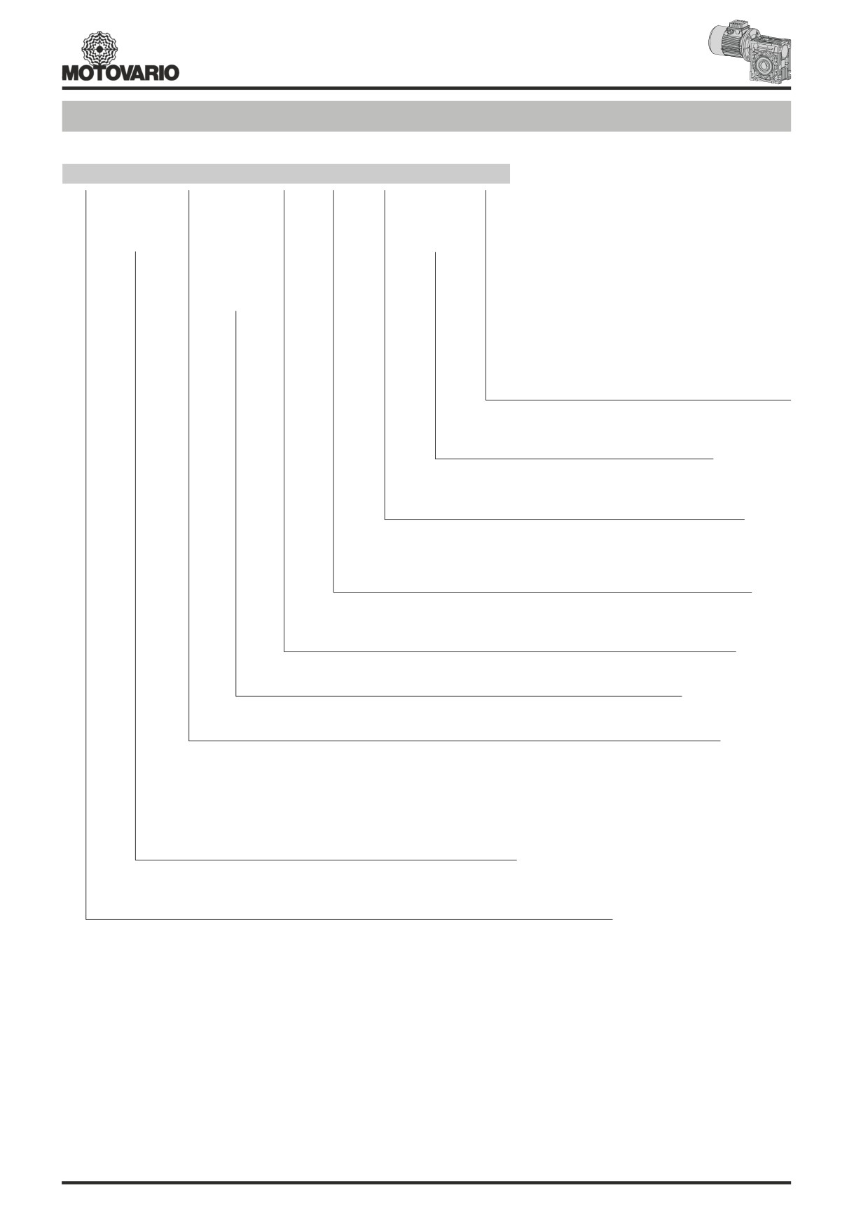
Designazione / Designation / Bezeichnung / Désignation / Designación NMRV - NRV
NMRV
050
FA
030
160x14
VS
125
25
B3
…….
NMRV
025
FA
5
PAM
B3
NRV
030
FB
7,5
ECE
B8
040
FC
10
B6
050
FD
15
B7
063
FE
20
V5
075
25
V6
090
30
105
40
Accessori - Accessories - Zubehör
110
50
Accessoires - Accesorios
130
60
Braccio di reazione - Alberi lenti - Cappellotto
150
80
Torque arm - Low speed shafts - Cover
100
Drehmomentstütze - Abtriebswellen - Deckel
Bras de réaction - Arbres pv - Capuchon
Brazo de rea - Ejes lentos - Tapa
Posizione di piazzamento - Mounting position
Einbaulage - Position de montage
Posición de montaje
Ø Albero uscita - Ø Output shaft - Ø Abtriebswelle
Ø Arbre de sortie - Ø Eje de salida
Ø Flangia uscita - Ø Output flange - Ø Abtriebsflansch
Ø Bride de sortie - Ø Brida de salida
Vite senza fine bisporgente - Double input shaft
Schnecke mit doppeltem Wellenende - Vis double sortie
Tornillo sinfin prolongado
Dimensioni entrata - Input dimensions - Abmessungen antriebsseitig
Dimensions d'entrée - Dimensiones entrada
Predisposto per attacco motore
Diametro albero d'entrata
Fitted for motor coupling
Input shaft diameter
PAM
für Motoranbau vorbereitet
ECE Durchmesser der Eingangswelle
(160x14)
Prédisposé pour montage moteur
(28)
Diamètre de l'arbre d'entrée
Predispuesto para montaje motor
Diámetro eje de entrada
Rapporto di riduzione - Reduction ratio - Übersetzungsverhältnis
Rapport de réduction - Relación de reducción
Flangia di uscita - Output flange - Abtriebsflansch - Bride de sortie - Brida de salida
Grandezza - Size - Baugröße - Grandeur - Tamaño
Tipo riduttore - Gearbox type - Getriebetyp - Type du reductteur - Tipo reductore
Motoriduttore a vite senza fine predisposto per motore
Worm geared motor
NMRV Schneckengetriebemotor
Motoréducteur à vis sans fin
Motorreductor de tornillo sinfín
Riduttore a vite senza fine
Worm reduction unit
NRV
Schneckengetriebe (mit Eingangswelle)
Réducteur à vis sans fin
Reductor de tornillo sinfín
226
Designazione / Designation / Bezeichnung / Désignation / Designación
PC+NMRV
PC
071
NMRV 050
120
120x14
25
BS B3
063
040
AS
071
050
BS
080
063
VS
090
075
PS
090
105
110
130
Posizione di piazzamento - Mounting position
Einbaulage - Position de montage
Posición de montaje
Esecuzione - Execution - Paarungsform
Exécution - Ejecucción
Ø Albero uscita - Ø Output shaft - Ø Abtriebswelle
Ø Arbre de sortie - Ø Eje de salida
Dimensioni entrata NMRV - Input dimensions NMRV
Abmessungen antriebsseitig NMRV
Dimensions d'entrée NMRV - Dimensiones entrada NMRV
Rapporto di riduzione - Reduction ratio - Übersetzungsverhältnis
Rapport de réduction - Relación de reducción
Grandezza - Size - Baugröße - Grandeur - Tamaño
Tipo riduttore - Gearbox type - Getriebetyp - Type du reductteur - Tipo reductore
Motoriduttore a vite senza fine predisposto per motore
Worm geared motor
NMRV Schneckengetriebemotor
Motoréducteur à vis sans fin
Motorreductor de tornillo sinfín
Grandezza - Size - Baugröße - Grandeur - Tamaño
Precoppia di riduzione - Pre-stage helical module - Übersetzungsvorstufe
Précouple de réduction - Pre-reducción
227

Designazione / Designation / Bezeichnung / Désignation / DesignaciónNMRV+NMRV
NRV+NMRV
NMRV+NMRV 050+110
FA
900 160x14
40
BS1
B3
NMRV+NMRV
025+030
FA
PAM
AS1
NRV+NMRV
025+040
FB
ECE
AS2
030+040
FC
BS1
030+050
FD
BS2
030+063
FE
VS1
040+075
VS2
040+090
PS1
050+105
PS2
050+110
063+130
063+150
Posizione di piazzamento - Mounting position
Einbaulage - Position de montage
Posición de montaje
Esecuzione - Execution - Paarungsform
Exécution - Ejecucción
Ø Albero uscita - Ø Output shaft - Ø Abtriebswelle
Ø Arbre de sortie - Ø Eje de salida
Dimensioni entrata - Input dimensions - Abmessungen antriebsseitig
Dimensions d'entrée - Dimensiones entrada
Predisposto per attacco motore
Diametro albero d'entrata
Fitted for motor coupling
Input shaft diameter
PAM für Motoranbau vorbereitet
ECE Durchmesser der Eingangswelle
(160x14) Prédisposé pour montage moteur
(28) Diamètre de l'arbre d'entrée
Predispuesto para montaje motor
Diámetro eje de entrada
Rapporto di riduzione - Reduction ratio - Übersetzungsverhältnis
Rapport de réduction - Relación de reducción
Flangia di uscita - Output flange - Abtriebsflansch - Bride de sortie - Brida de salida
Grandezza - Size - Baugröße - Grandeur - Tamaño
Tipo riduttore - Gearbox type - Getriebetyp - Type du reductteur - Tipo reductore
Motoriduttore a vite senza fine combinato
Combined worm geared motor
NMRV+NMRV
zweistufiger Schneckengetriebemotor
Motoréducteur á vis sans fin combiné
Motorreductor de tornillo sinfin combinado
Riduttore a vite senza fine combinato
Combined worm reduction unit
NRV+NMRV
zweistufiges Schneckengetriebe (mit Eingangswelle)
Réducteur á vis sans fin combiné
Reductor de tornillo sinfin combinado
228
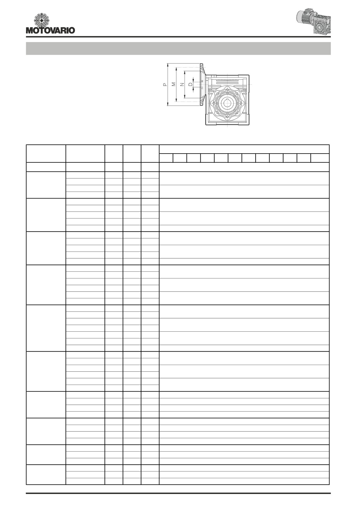
Predisposizione / Predisposition / Motoranbau / Prédisposition / Predisposición
(*) Linguetta ribassata di nostra fornitura.
(*) Low profile key supplied by Motovario
(*) Abgeflachte Paßfeder im Lieferumfang.
(*) Clavette surbaissée fournie.
(*) Chavetero rebajado de nuestro suministro
PAM
D
NMRV
N
M
P
IEC
5
7,5
10
15
20
25
30
40
50
60
80
100
025
56B14
50
65
80
9
9
9
9
9
-
9
9
9
9
-
-
63B5
95
115
140
11
11
11
11
11
11
11
11
11
-
-
-
63B14
60
75
90
030
56B5
80
100
120
9
9
9
9
9
9
9
9
9
9
9
-
56B14
50
65
80
71B5
110
130
160
14
14
14
14
14
14
14
14
-
-
-
-
71B14
70
85
105
040
63B5
95
115
140
11
11
11
11
11
11
11
11
11
11
11
11
63B14
60
75
90
56B5
80
100
120
-
-
-
-
-
-
-
-
9
9
9
9
80B5
130
165
200
19
19
19
19
19
19
19
-
-
-
-
-
80B14
80
100
120
050
71B5
110
130
160
14
14
14
14
14
14
14
14
14
14
14
-
71B14
70
85
105
63B5
95
115
140
-
-
-
-
-
-
-
11
11
11
11
11
90B5
130
165
200
-
24
24
24
24
24
24
-
-
-
-
-
90B14
95
115
140
80B5
130
165
200
-
19
19
19
19
19
19
19
19
19
-
-
063
80B14
80
100
120
71B5
110
130
160
-
-
-
-
-
-
-
14
14
14
14
14
71B14
70
85
105
100/112B5
180
215
250
-
28
28
28
-
-
-
-
-
-
-
-
100/112B14
110
130
160
90B5
130
165
200
-
24
24
24
24
24
24
24
-
-
-
-
075
90B14
95
115
140
80B5
130
165
200
-
-
-
-
19
19
19
19
19
19
19
19
80B14
80
100
120
71B5
110
130
160
-
-
-
-
-
-
-
-
14
14
14
14
100/112B5
180
215
250
-
28
28
28
28
28
28
-
-
-
-
-
100/112B14
110
130
160
90B5
130
165
200
-
24
24
24
24
24
24
24
24
24
-
-
090
90B14
95
115
140
80B5
130
165
200
-
-
-
-
-
-
-
19
19
19
19
19
80B14
80
100
120
132B5
230
265
300
-
38*
38*
38*
38*
-
-
-
-
-
-
-
100/112B5
180
215
250
-
28
28
28
28
28
28
28
28
28
-
-
105
90B5
130
165
200
-
-
-
-
-
24
24
24
24
24
24
24
80B5
130
165
200
-
-
-
-
-
-
-
-
-
-
19
19
132B5
230
265
300
-
38*
38*
38*
38*
-
-
-
-
-
-
-
100/112B5
180
215
250
-
28
28
28
28
28
28
28
28
28
-
-
110
90B5
130
165
200
-
-
-
-
-
24
24
24
24
24
24
24
80B5
130
165
200
-
-
-
-
-
-
-
-
-
-
19
19
132B5
230
265
300
-
38*
38*
38*
38*
38*
38*
38*
-
-
-
-
130
100/112B5
180
215
250
-
-
-
-
-
28
28
28
28
28
28
28
90B5
130
165
200
-
-
-
-
-
-
-
-
-
-
24
24
160B5
250
300
350
-
42
42
42
42
42
-
-
-
-
-
-
150
132B5
230
265
300
-
-
-
-
38
38
38
38
38
38
-
-
100/112B5
180
215
250
-
-
-
-
-
-
-
-
28
28
28
28
229
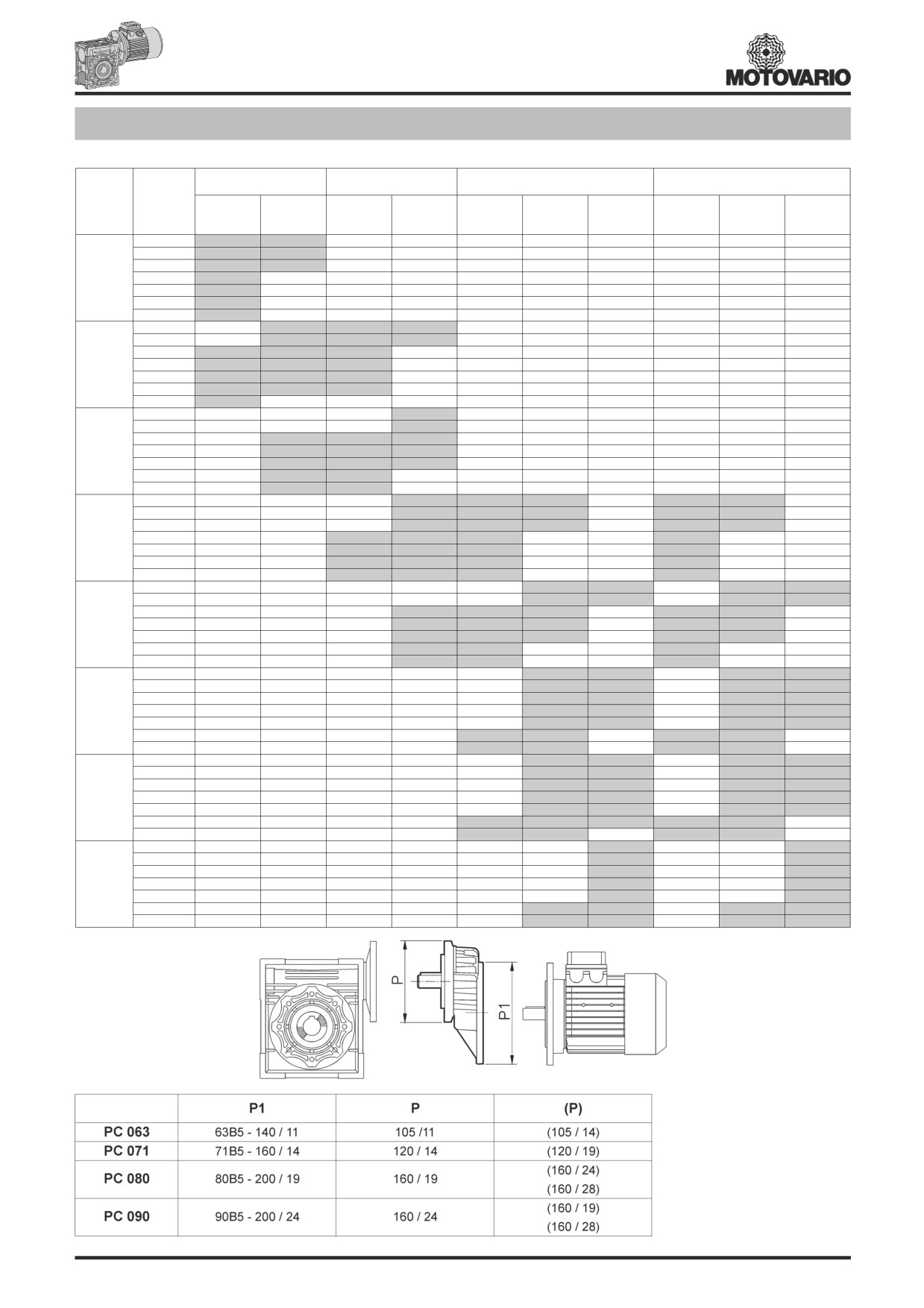
PC+NMRV Combinazioni / Combinations / Kombinationen / Combinaisons / Combinaciónes
PC 063
PC 071
PC 080
PC 090
NMRV
i
105 / 11
105 / 14
120 / 14
120 / 19
160 / 19
160 / 24
160 / 28
160 / 19
160 / 24
160 / 28
i = 3
i = 3
i = 3
i = 3
i = 3
i = 3
i = 3
i = 2,42
i = 2,42
i = 2,42
25
30
40
040
50
60
80
100
25
30
40
050
50
60
80
100
25
30
40
063
50
60
80
100
25
30
40
075
50
60
80
100
25
30
40
090
50
60
80
100
25
30
40
105
50
60
80
100
25
30
40
110
50
60
80
100
25
30
40
130
50
60
80
100
(..) Solo su richiesta
(..) Only on request
(..) Auf Wunsch
(..) Seulement sur demande
(..) Sòlo bajo pedido
230
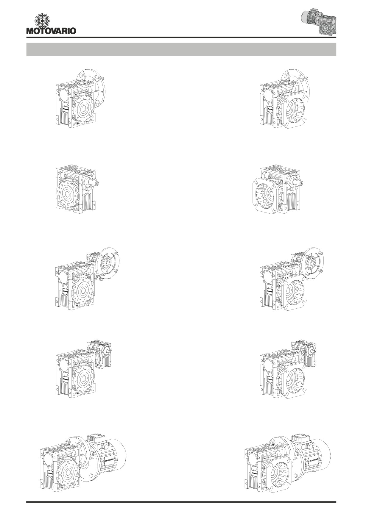
Versioni / Versions / Ausführungen / Versions / Versiones
NMRV 025-150
NMRV 025-150 F
NRV 030-150
NRV 030-150 F
NMRV-NMRV...
NMRV-NMRV...F
NRV-NMRV...
NRV-NMRV...F
PC-NMRV...
PC-NMRV...F
231
Rendimento - Irreversibilità dinamica - Irreversibilità statica
RENDIMENTO
IRREVERSIBILITA’ DINAMICA
Un parametro che influisce in maniera determinante nella definizione di
L’irreversibilità dinamica si realizza quando al venir meno del moto
talune applicazioni è il rendimento.
sull’asse della vite, si ha un arresto istantaneo del moto sull’asse
Il rendimento dipende essenzialmente da elementi definiti dal progettista
dell’albero lento. Questa condizione si realizza quando il rendimento
all’atto del progetto della coppia.
dinamico è hd<0.5 (tab. pag.234).
La tabella dei dati di dentatura (pag.24) riporta i valori di rendimento
IRREVERSIBILITA’ STATICA
dinamico (n1=1400) e rendimento statico. I valori indicati vengono
L’irreversibilità statica si realizza quando, a riduttore fermo, l’applica-
raggiunti solo dopo la fase di rodaggio.
zione di un carico all’albero lento non mette in movimento l’asse della
vite. Questa condizione si realizza quando il rendimento statico è
hs<0.5 (tab. pag.234).
N.B.: La presenza di vibrazioni o urti può modificare le condi-
zioni sopra descritte.
Efficiency - Dynamic irreversibility - Static irreversibility
EFFICIENCY
DYNAMIC IRREVERSIBILITY
Efficiency is a parameter which has a major influence on the sizing of
Dynamic irreversibility is achieved when the output shaft stops instantly
certain applications, and basically depends on gear pair design
when drive is no longer transmitted through the worm shaft. This
elements.
condition requires a dynamic efficiency of hd < 0.5 (see table on page 234).
The mesh data table on page 24 shows dynamic efficiency (n1=1400)
STATIC IRREVERSIBILITY
and static efficiency values. Remember that these values are only
Static irreversibility is achieved when, with the gear reducer at a
achieved after the unit has been run in.
standstill, the application of a load to the output shaft does not set in
motion the worm shaft. This condition requires a static efficiency of
hs < 0.5 (see table on page 234).
N.B.: Vibrations and shocks can affect a gear reducer’s
irreversibility.
Wirkungsgrad - Dynamische Selbsthemmung - Statische Selbsthemmung
Wirkungsgrad
Dynamische Selbsthemmung
Der Wirkungsgrad ist für die Art der Anwendung wichtig.
Im Zustand dynamischer Selbsthemmung tritt sofortiger Stillstand der
Er wird entscheidend von den Verzahnungsdaten beeinflußt.
Abtriebswelle ein, wenn die Schneckenwelle nicht mehr angetrieben
In der Übersicht der Verzahnungsdaten (S. 24) finden Sie die Werte
wird.
des dynamischen (n1 = 1400) und statischen Wirkungsgrades. Es
Die theoretische Voraussetzung für dynamische Selbsthemmung ist
wird darauf hingewiesen, daß diese Tabellenwerte erst nach der
ein dynamischer Wirkungsgrad hd <0,5 (Tab. Seite 234).
Einlaufzeit gültig sind.
Statische Selbsthemmung
Bei statischer Selbsthemmung ist ein Anlauf aus dem Stillstand bei
treibendem Schneckenrad nicht möglich.
Statische Selbsthemmung liegt bei einem statischen Wirkungsrad
hs< 0,5 vor (Tab. Seite 234).
N.B.: Die oben genannten Bedingungen können durch
Vibrationen oder Stöße beeinträchtigt werden.
Rendement - Irréversibilite dynamique - Irréversibilite statique
RENDEMENT
IRREVERSIBILITE DYNAMIQUE
Le rendement est un facteur qui influe considérablement sur la définition
L’irréversibilité dynamique s’obtient lorsqu’à l’interruption du mouvement
de certaines applications.
sur l’axe de la vis correspond un arrêt instantané du mouvement sur
Le rendement dépend principalement d’éléments définis par le l’arbre PV.
concepteur au moment de la réalisation du projet du couple.
Cette condition se réalise lorsque le rendement dynamique est hd < 0,5
Le tableau des données de denture (page 24) montre les valeurs de
(tabl. page 234).
rendement dynamique (n1=1400) et de rendement statique. Noter que IRREVERSIBILITE STATIQUE
les valeurs indiquées ne sont atteintes qu’après la phase de rodage.
L’irréversibilité statique s’obtient lorsque, réducteur arrêté, l’application
d’une charge sur l’arbre PV ne meut pas l’axe de la vis.
Cette condition se réalise lorsque le rendement statique est hs < 0,5
(tabl. page 234).
N.B.: La présence de vibrations ou de chocs peut modifier
les conditions susmentionnées.
Rendimiento - Irreversibilidad dinamica - Irreversibilidad estatica
RENDIMIENTO
IRREVERSIBILIDAD DINAMICA
Un parámetro que reviste importancia fundamental en la definición de
La irreversibilidad dinámica se produce cuando, al faltar el movimiento
algunas aplicaciónes es el rendimiento.
en el eje del tornillo, se produce una detención instantánea en el eje del
El rendimiento depende esencialmente de variables definidas por el
árbol lento.
proyectista al momento de definir el par.
Esta situación se produce cuando el rendimiento dinámico es hd<0,5
La tabla de los datos del dentado (pág. 24) indica los valores de
(tab. pág. 234).
rendimiento dinámico (nl=1400) y rendimiento estático. Los valores
IRREVERSIBILIDAD ESTATICA
indicados son alcanzados sólo una vez concluida la fase de rodaje.
La irreversibilidad estática se produce cuando, con el reductor
detenido, la aplicación de una carga al árbol lento no pone en movimiento
el eje del tornillo.
Esta situación se produce cuando el rendimiento estático es hs<0,5
(tab. pág. 234).
N.B.: La presencia de vibraciónes o choques podría modificar
estos valores.
232
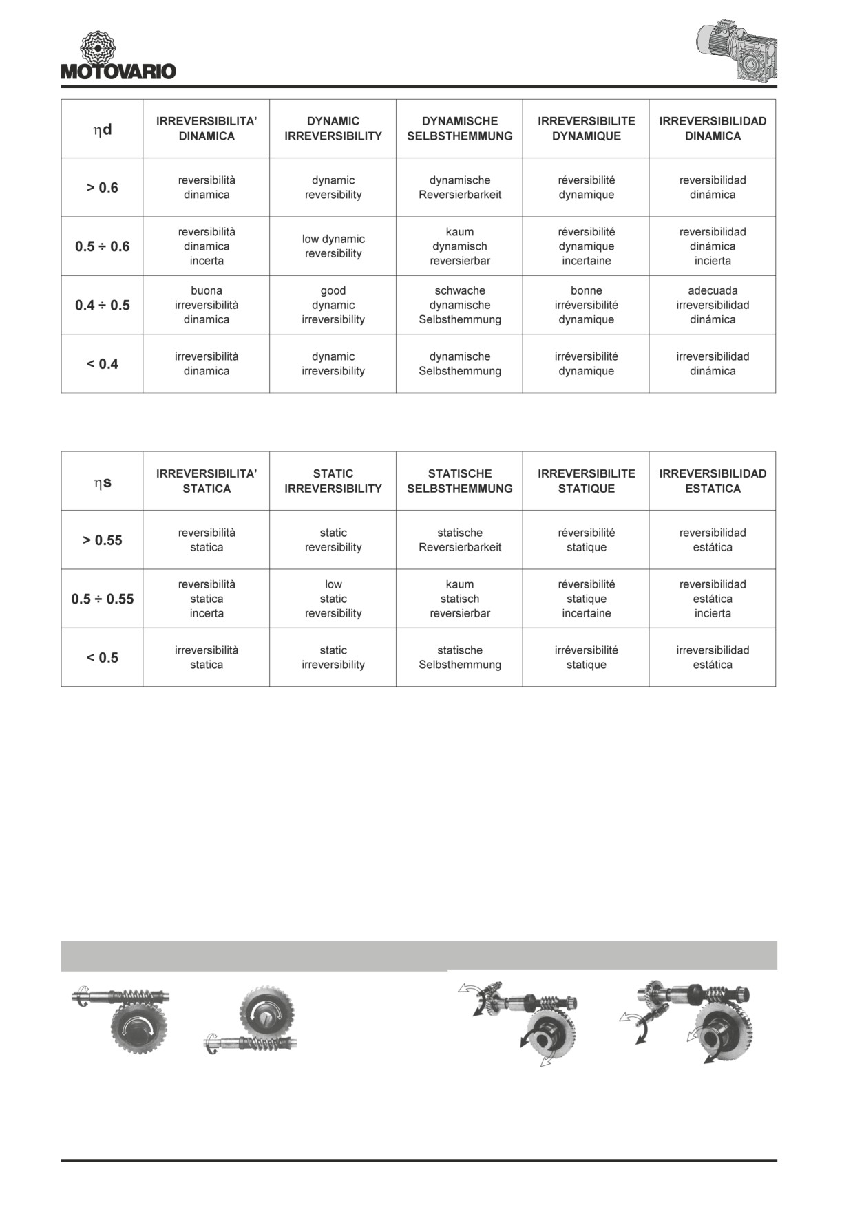
La tabella riporta classificazioni indicative sul grado di irreversibilità.
Per i riduttori combinati verificare la condizione di irreversibilità sul gruppo con rendimento più basso.
The table shows approximate irreversibility classes.
The irreversibility condition of combined gear reducers is given by the units with the lowest efficiency.
In der Übersicht sind die Angaben zur Selbsthemmung nur als Richtwerte wiedergegeben.
Auf die zweistufige Schneckengetriebemotoren ist die Selbsthemmungsbedingung durch das Getriebe mit dem kleinest Wirkungsgrad gegeben.
Le tableau montre la classification indicative sur le degré d’irréversibilité.
La condition d’irréversibilité des réducteurs combinés est donnée par le groupe avec rendement plus faible.
La tabla indica clasificaciones genéricas sobre el grado de irreversibilidad.
En caso de reductores combinados verifiquen la irreversibilidad sobre el grupo con rendimiento más bajo.
Senso di rotazione / Direction of rotation / Drehsinn / Sens de rotation / Sentido de rotacion
NMRV - NRV
NMRV+NMRV - NRV+NMRV
Il senso dell’elica è destro. - The helix is right-handed. - Die Schnecke ist rechtsgängig. - Le sens d’hélice est à droite. - El sentido de la hélice es hacia la derecha.
233

Dati ingranamento / Mesh data / Verzahnungsdaten / Données des engranages / Datos engrane
NRV
i
5
7,5
10
15
20
25
30
40
50
60
80
100
Z1
6
4
3
2
2
1
1
1
1
g
3
02'
2
03'
1
19'
1
09'
1
41'
40'
23'
31'
53'
025
Mx
1,3
1,3
1,3
1,3
0,995
1,3
0,995
0,8
0,67
hd(1400)
0,87
0,85
0,83
0,79
0,75
0,67
0,62
0,58
0,55
hs
0,72
0,71
0,68
0,61
0,56
0,46
0,41
0,36
0,34
Z1
6
4
3
2
2
1
1
1
1
1
1
g
2
04'
1
49'
1
20'
40'
42'
35'
52'
52'
12'
45
'
07'
030
Mx
1,44
1,44
1,44
1,44
1,09
1,7
1,44
1,09
0,89
0,74
0,56
hd(1400)
0,87
0,85
0,82
0,77
0,73
0,68
0,65
0,59
0,55
0,51
0,44
hs
0,72
0,67
0,63
0,55
0,5
0,43
0,39
0,35
0,31
0,27
0,23
Z1
6
4
3
2
2
2
1
1
1
1
1
1
g
3
19'
2
28'
1
51'
1
49'
1
23'
43'
29'
14'
23'
3
4°
7'
57'
2°5'
040
Mx
2,06
2,06
2,06
2,06
1,57
1,27
2,06
1,57
1,27
1,06
0,81
0,65
hd(1400)
0,89
0,87
0,85
0,82
0,78
0,75
0,7
0,65
0,62
0,58
0,52
0,47
hs
0,74
0,71
0,67
0,6
0,55
0,51
0,45
0,4
0,36
0,32
0,28
0,24
Z1
6
4
3
2
2
2
1
1
1
1
1
1
g
33°7'
2
54'
1
23'
1
30'
10°6'
29'
19'
06'
16'
3
4°
0'
52'
2°1'
050
Mx
2,56
2,56
2,56
2,56
1,95
1,58
2,56
1,95
1,58
1,32
1
0,8
hd(1400)
0,89
0,88
0,86
0,82
0,79
0,76
0,72
0,67
0,63
0,59
0,53
0,49
hs
0,74
0,7
0,66
0,59
0,55
0,51
0,44
0,39
0,35
0,32
0,27
0,23
Z1
4
3
2
2
2
1
1
1
1
1
1
g
2
31'
1
53'
1
51'
1
25'
45'
30'
15'
24'
47'
2°
58'
26'
063
Mx
3,25
3,25
3,25
2,48
2
3,25
2,48
2
1,68
1,27
1,02
hd(1400)
0,88
0,87
0,83
0,81
0,78
0,74
0,7
0,66
0,62
0,57
0,51
hs
0,71
0,67
0,6
0,55
0,51
0,45
0,4
0,36
0,33
0,28
0,24
Z1
4
3
2
2
2
1
1
1
1
1
1
g
2
17'
2
20'
1
52'
11°8'
32'
02'
42'
4°8'
08'
3°
14'
40'
075
Mx
3,94
3,94
3,94
3
2,42
3,94
3
2.42
2,03
1,54
1.24
hd(1400)
0,91
0,9
0,87
0,85
0,83
0,8
0,77
0,74
0,71
0,66
0,61
hs
0,71
0,68
0,61
0,57
0,53
0,46
0,42
0,38
0,35
0,29
0,26
Z1
4
3
2
2
2
1
1
1
1
1
1
g
2
11'
2
44'
1
36'
1
50'
1
54'
57'
30'
30'
4°6'
3
4°
5'
06'
090
Mx
4,84
4,84
4,84
3,69
2,98
4,84
3,69
2,98
2,5
1,89
1,52
hd(1400)
0,9
0,89
0,86
0,84
0,82
0,78
0,75
0,72
0,69
0,63
0,59
hs
0,73
0,7
0,64
0,6
0,56
0,49
0,45
0,41
0,38
0,32
0,28
Z1
4
3
2
2
2
1
1
1
1
1
1
g
2
15'
2
57'
1
02'
14°1'
1
34'
39'
28'
22'
32'
4
2°
4'
3°9'
105
Mx
5,875
5,875
5,875
4,62
3,73
5,875
4,62
3,73
3,13
2,37
1,91
hd(1400)
0,9
0,89
0,86
0,85
0,84
0,79
0,78
0,75
0,72
0,67
0,63
hs
0,72
0,69
0,63
0,62
0,59
0,48
0,48
0,44
0,41
0,36
0,32
Z1
4
3
2
2
2
1
1
1
1
1
1
g
2
15'
2
57'
1
02'
14°1'
1
34'
39'
28'
22'
32'
4
2°
4'
3°9'
110
Mx
5,875
5,875
5,875
4,62
3,73
5,875
4,62
3,73
3,13
2,37
1,91
hd(1400)
0,9
0,89
0,86
0,85
0,84
0,79
0,78
0,75
0,72
0,67
0,63
hs
0,72
0,69
0,63
0,62
0,59
0,48
0,48
0,44
0,41
0,36
0,32
Z1
4
3
2
2
2
1
1
1
1
1
1
g
2
41'
2
19'
1
18'
1
52'
1
49'
47'
02'
5°8'
11'
4
0°
7'
24'
130
Mx
6,97
6,97
6,97
5,4
4,37
6,97
5,4
4,37
3,67
2,77
2,23
hd(1400)
0,91
0,89
0,87
0,86
0,84
0,8
0,78
0,75
0,72
0,68
0,64
hs
0,72
0,69
0,63
0,61
0,58
0,49
0,46
0,43
0,39
0,34
0,3
Z1
6
4
3
2
2
2
1
1
1
1
1
g
3
09'
2
35'
1
27'
1
53'
11°9'
50'
32'
43'
57'
3
5°
5'
14'
150
Mx
5,5
6,155
5,5
6,155
5
4,193
6,155
5
4,193
3,17
2,55
hd(1400)
0,91
0,9
0,88
0,86
0,84
0,83
0,78
0,76
0,73
0,68
0,64
hs
0,73
0,71
0,66
0,6
0,57
0,54
0,45
0,42
0,39
0,33
0,29
234
Caratteristiche costruttive ( PC )
La costruzione della precoppia è modulare e pertanto può essere
Materiali
fornita come gruppo separato da montare su qualsiasi tipo di
Cassa in lega di alluminio.
motoriduttore predisposto (PAM). A tale proposito le varie possibilità di
Ingranaggi in acciaio 20MnCr5 (UNI7846) cementati,temprati,rinvenuti
flange/alberi di uscita sono rilevabili a pag. 230.
e accuratamente rettificati sull’evolvente.
Il montaggio della precoppia sul riduttore principale viene eseguito in
maniera agevole come un qualsiasi motore in forma B14.
La precoppia non può essere utilizzata in maniera singola, ma solo
accoppiata ad un altro riduttore.
Design features ( PC )
The PC construction is modular and therefore it can be supplied as a
Materials
separate unit to be mounted on any type of fitted geared motor (PAM).
Case in aluminium alloy.
In this connection, the various possibilities of flange/output shafts can
Gears in case hardened, hardened, tempered steel 20MnCr5 (UNI7846)
be found on page 230.
accurately ground on the involute.
Fitting the pre-stage helical module on the main reduction unit is easily
done as for any motor of type B14.
The pre-stage unit cannot be used by itself, but only coupled with
another reduction unit.
Baueigenschaften ( PC )
Die Bauweise der Übersetzungsvorstufe ist modular und kann daher
Werkstoffe
als getrenntes Aggregat geliefert und auf einem Schneckengetriebe
Gehäuse aus Alulegierung.
mit
“PAM”-Flansch montiert werden. Die unterschiedlichen
Zahnräder aus Stahl 20MnCr5 (UNI7846), einsatzgehärtet und
Kombinationsmöglichkeiten von Flanschen/Wellen zeigt Seite 230.
angelassen, Evolvente geschliffen.
Die Montage der Vorstufe am Hauptgetriebe kann sehr einfach wie bei
jedem Motor im Bauform B14 durchgeführt werden.
Die Vorstufe kann nicht einzeln, sondern nur zusammen mit einem
anderen Getriebe eingesetzt werden.
Caractéristiques de construction ( PC )
Materiaux
La construction du précouple est modulaire et il peut donc être livré
comme groupe séparé à monter sur n’importe quel type deCarcasse en alliage d’aluminium.
motoréducteur prédisposé (PAM). A cet égard, les différentesEngrenages en acier 20MnCr5 (UNI7846) cémentés, trempés, revenus
et soigneusement rectifiés.
possibilités de brides/arbre de sortie sont mentionnées à la page 230.
Le montage du précouple sur le réducteur principal s’effectue très
facilement, comme pour tout autre moteur de forme B14.
Le précouple ne peut pas être utilisé tout seul, mais seulement accouplé
à un autre réducteur.
Caracteristicas de construcción ( PC )
La construcción de la pre-reducción es modular y por lo tanto puede
Materiales
ser entregada como grupo separado de montar sobre cualquier tipo
Caja de aleación de aluminio.
de motoreductor predispuesto (PAM). Las distintas posibilidades de
Engranajes de acero 20MnCr5 (UNI7846) cementados, templados,
bridas/ejes de salida son indicadas en la página 230.
revenidos y cuidadosamente rectificado sobre la evolvente.
El montaje de la pre-reducción sobre el reductor principal se efectúa
muy facilmente, como para cualquier motor de forma B14.
El pre-reductor no puede ser utilizado directamente como reductor,
solo puede ir acoplado a otro reductor.
235
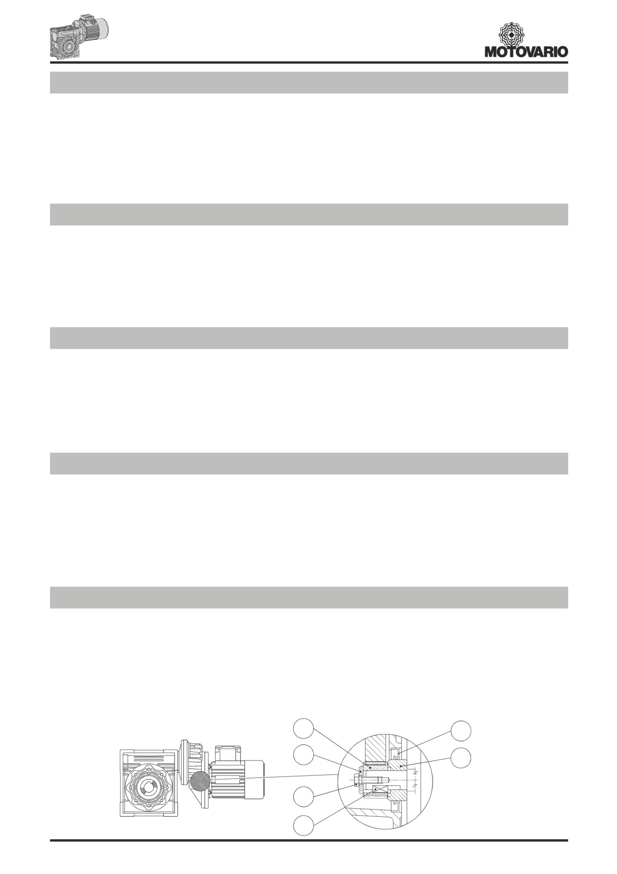
Montaggio motore elettrico
Per il corretto montaggio del pignone sull’albero del motore elettrico
e)Montare il pignone (4) adottando gli stessi accorgimenti descritti al
occorre attenersi alle seguenti istruzioni:
punto (c).
a)Pulire accuratamente l’albero del motore elettrico.
f) Montare la rondella (5) e serrare tramite la vite (6).
b)Togliere la linguetta del motore dalla sede.
g)Togliere il tappo di chiusura in gomma montato sulla sede dell’anello
c)Montare la boccola (1) sull’albero motore secondo l’orientamento
di tenuta, facendo attenzione in quanto il gruppo precoppia è già
indicato nello schema. Per facilitare il montaggio si può riscaldare
completo di lubrificante.
la boccola a circa 70/8C°.
h)Montare l’anello di tenuta (2) e quindi il gruppo motore curando
d)Montare la nuova linguetta (3) fornita a corredo al posto di quella
l’inserimento affinchè non si danneggi il labbro dell’anello di tenuta.
precedentemente tolta.
N.B. Per un corretto funzionamento, esente da vibrazioni e rumorosità,
si consiglia di adottare motori di buona qualità.
Coupling to electric motor
Correctly fitting the pinion on the electric motor shaft requires you
e)Fit the pinion (4) taking the same precautions as described in
keep to the following instructions:
point (c).
a)Thoroughly clean the electric motor shaft.
f) Fit the washer (5) and tighten with the screw (6).
b)Remove the motor key from its seat.
g)Remove the rubber cap mounted on the seat of the oil seal, taking
c)Fit the bush (1) to the drive shaft as shown in the diagram. To
care since the pre-stage unit is already complete with lubricant.
make this easier, you can heat the bush to approximately 70/8C°.
h)Fit the oil seal (2) and then the motor assembly, taking care not
d)Fit the new key (3) provided in place of the one removed
to damage the lip of the oil seal.
beforehand.
N.B. For correct operation, with no vibration or noise, it is recommended
to use good quality motors.
Montage des Elektromotors
Für eine einwandfreie Montage des Ritzels auf der Welle des
f) Scheibe (5) aufsetzen und mit Schraube (6) festziehen.
Elektromotors sind nachstehende Anweisungen zu beachten:
g)Gummi-Verschlußkappe am Sitz des Dichtrings vorsichtig
a) Welle des Elektromotors sorgfältig reinigen.
entfernen, da die Vorstufe mit Schmieröl gefüllt ist (Öffnung nach
b) Motorseitige Paßfeder abnehmen.
oben).
c)Buchse (1) auf die Motorwelle nach Schema aufziehen, ggf.
h)Dichtring (2) und Motor montieren; dabei ist darauf zu achten, daß
hierzu Buchse auf ca. 70/8C° erwärmen und aufschru mpfen.
die Lippe des Dichtrings nicht beschädigt wird.
d)Neue Paßfeder (3) anstelle der ursprünglichen einsetzen.
Anmerkung: für eine schwingungsfreie und geräuscharme Funktion
e)Ritzel (4) montieren (ggf. erwärmen).
sollten Motoren mindestens mit Toleranzen nach DIN 42955N eingesetzt
werden.
Montage du moteur électrique
Pour le montage correct du pignon sur l’arbre du moteur électrique, il
f) Monter la rondelle (5) et serrer à l’aide de la vis (6).
faut respecter les instructions suivantes:
g)Enlever le bouchon en caoutchouc monté sur le siège de la bague
a)Nettoyer soigneusement l’arbre du moteur électrique.
d’étanchéité, en faisant attention, car le groupe précouple
b)Enlever la clavette du moteur de son siège.
contient du lubrifiant.
c)Monter la douille (1) sur l’arbre-moteur suivant l’orientation
h)Monter la bague d’étanchéité (2) et ensuite le groupe moteur avec
indiquée dans le schéma. Pour faciliter le montage, on peut
beaucoup de soin, pour ne pas endommager la lévre de la bague
chauffer la douille à environ 70/8C°.
d’étanchéité.
d)Monter la nouvelle clavette (3) au lieu de celle précédemment enlevée.
NOTE: Pour un fonctionnement correct, sans vibrations et bruits, on
e)Monter le pignon (4) en adoptant les mesures indiquées au point (c).
conseille d’utiliser des moteurs de bonne qualité.
Montaje motor electrico
Para el correcto montaje del piñon sobre el eje del motor eléctrico, es
e)Montar el piñon (4) adoptando las mismas precauciónes indicadas
necesario respetar las siguientes instrucciónes:
al punto (c).
a)Limpiar con cuidado el eje del motor eléctrico.
f) Montar la arandela (5) y apretar con el tornillo (6).
b)Sacar la chaveta del motor.
g)Sacar con cuidado el tapón de cierre de goma montado en el asiento
c)Montar el casquillo (1) sobre el eje motor según la orientación
del anillo de retén, porque el pre-reductor par está equipado de
indicada en el esquema. Para facilitar el montaje, se puede calentar
lubricante.
el casquillo a aprox.70/8C°.
h)Montar el retén (2) y luego el grupo motor con mucho cuidado para
d)Montar la nueva chaveta (3) entregada en lugar de la anteriormente
no dañar el labio del retén.
sacada.
Nota: para un correcto funcionamiento sin vibraciónes ní ruidos, se
aconseja montar motores de buena calidad.
4
2
5
1
6
3
236
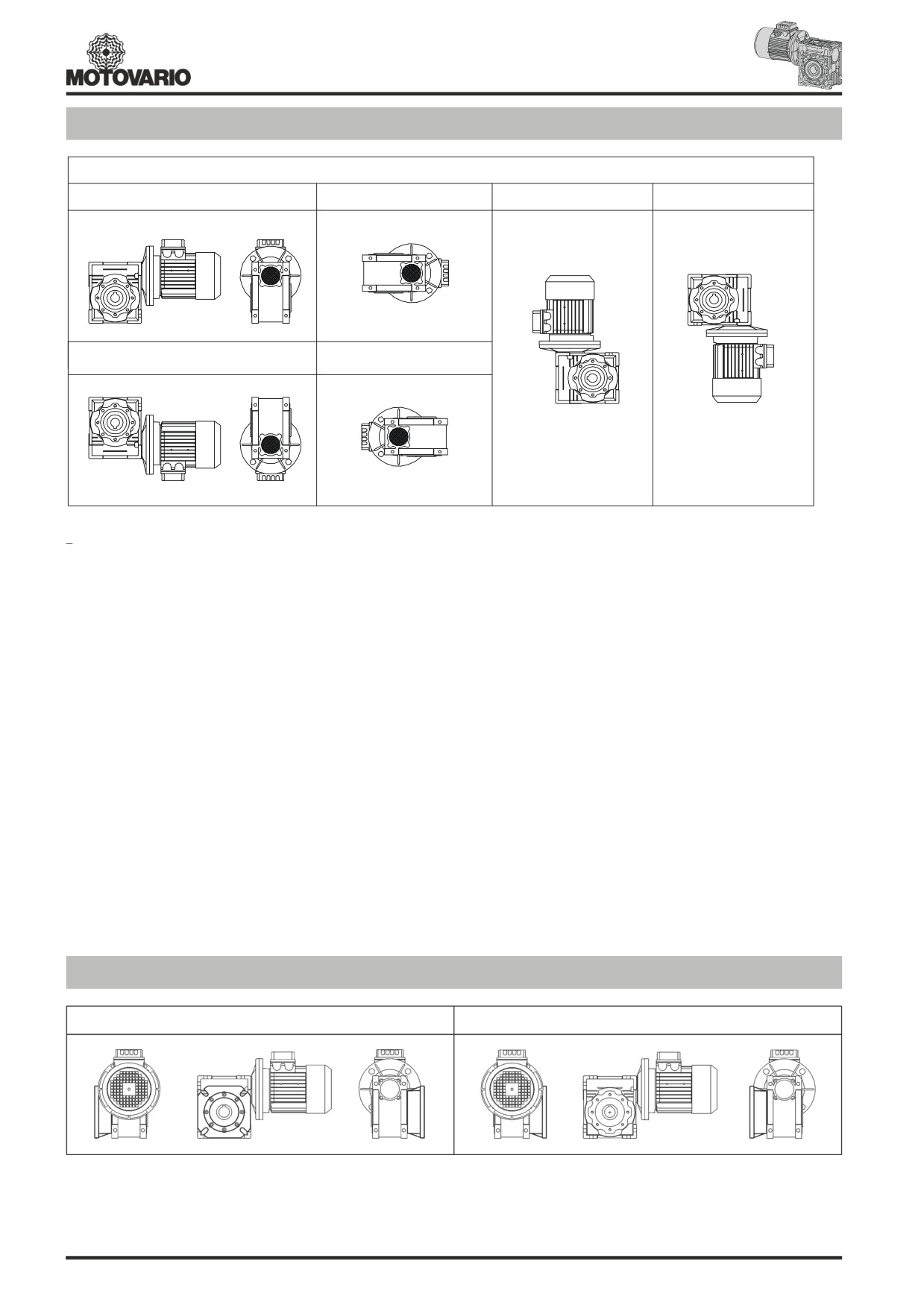
Piazzamento / Mounting positions / Einbaulage / Pos. de montage / Pos. de montaje
NMRV - NRV
NMRV...U - B3
B6
V5
V6
1
1
1
1
B8
B7
1
1
- La versione “U” è relativa alle gr.NMRV 025-075 e NRV 030-063. Per queste grandezze non è necessario specificare la posizione di piazzamento.
- Per le posizioni di piazzamento verticali verificare quanto detto a pag.10-11.
- Se non diversamente specificato le posizioni standard sono B3.
- Per le posizioni di piazzamento non previste occorre rivolgersi al ns. Servizio tecnico.
-
“U” version is related to sizes from NMRV 025-075 and NRV 030-063. For these sizes it is not necessary to specify mounting position.
- For vertical positions, check with pages 10-11.
- Unless specified otherwise, the standard positions are B3.
- For positions not envisaged, it is necessary to call our Technical Service.
- Die Ausführung “U” bezieht sich auf die Baugröße von NMRV 025-075 und NRV 030-063. Für diesen Baugrößen ist die Angabe der
Einbaulage nicht erförderlich zu spezifizieren
- Für die vertikalen Einbaulagen siehe Seite 10-11.
- Falls nicht anders angegeben, sind B3 die Standardeinbaulagen.
- Für nicht angegebene Einbaulagen setzen Sie sich bitte mit unserem Kundendienst in Verbindung.
- La version “U” se réfère aux tailles de NMRV 025-075 et NRV 030-063. Pour ces tailles il n’est pas necessaire d’indiquer la position de montage.
- Pour les positions de montage verticales, voir pages 10 et 11.
- Si non spécifié, les positions standard sont B3.
- Pour les positions de montage non prévues, contacter notre S.ce technique.
- La version “U” se refiere a los tamanos de NMRV 025-075 y NRV 030-063. Para estos tamaño no es necesario especificar la posición de montaje.
- Para las posiciónes de montaje verticales, ver las páginas 10-11.
- Si no se especifica el contrario, las posiciónes estándar son B3.
- Para las posiciónes de montaje no previstas, es necesario ponerse en contacto con nuestro Servicio técnico.
Flangia F-FL / Flange F-FL / Flansch F-FL / Flasque F-FL / Flasque-bride F-FL
D
S
- Se non diversamente specificato il riduttore viene fornito con flangia in pos. D riferito alla posizione di piazzamento B3.
- Unless specified otherwise, the reduction unit is supplied with the flange in pos. D referred to position B3.
- Falls nicht anders vereinbart, wird das Getriebe mit Flansch in Position D, auf die B3-Einbaulage bezogen, geliefert.
- Si non différement spécifié, le réducteur est livré avec bride en pos. D correspondant à la position de montage B3.
- Si no diversamente especificado, el reductor se entrega con brida en pos. D, relacionado a la posición de montaje B3.
237
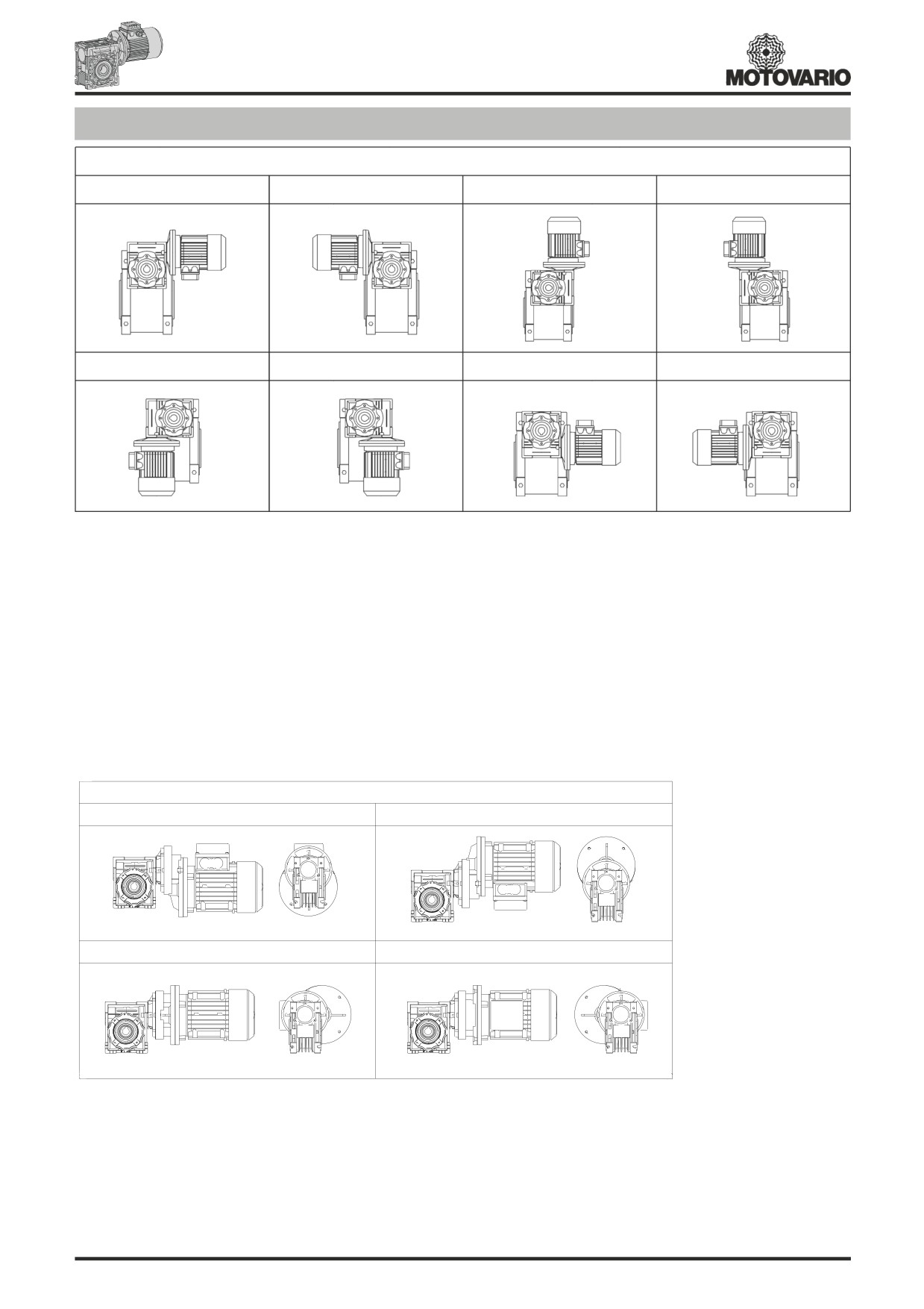
Esecuzione / Execution / Paarungsform / Exécution / Ejecucción
NMRV-NMRV / NRV-NMRV
AS1
AS2
VS1
VS2
1
1
3
3
PS1
PS2
BS1
BS2
3
3
1
1
- L'esecuzione determina la posizione di montaggio del
riduttore rispetto al
riduttore. Se non di v e rsamente specificato in fase d'ordine il
gruppo viene fornito in esecuzione BS2. La posizione di piazzamento va riferita al 2°riduttore, per l e posizioni previste vedere a pag. 238.
- The position of the 1st reducer with respect to the 2nd gear reducer depend on the version. Unless otherwise specified at the time of order,
combination groups are supplied in version BS2. The specified mounting position refers to the 2nd gear reducer. See page 238 for the
possible mounting positions.
- Die Paarungsform legt die Einbauanordnung des 1. Getriebe fest. Sofern nicht speziell in der Bestellbezeichnung angeführt, wird das
Getriebe in BS2 Form geliefert. Die Bauform bezieht sich auf das 2. Getriebe, siehe Seite 238 die verschiedenen Möglichkeiten.
- L'exécution détermine la position de montage du premiere réducteur par rapport au second. Sauf indication contraire à la commande,
l'ensemble est livré ex exécution BS2. La position de montage se rapporte au deuxième réducteur; pour les positions prévues, voir page 238.
- La ejecucción determina la posición de montaje del premier reductor respecto del segundo. Salvo diversas especificaciones requeridas en
el pedido, el grupo es suministrado en ejecución BS2. La posición de instalación se refiere al segundo reductor; en relación a las posiciones
previstas ver pág. 238.
PC - NMRV
BS
AS
1
1
1
VS
PS
1
1
N.B.: In fase d’ordine occorre sempre specificare l’esecuzione ed il piazzamento.
Se non diversamente specificato le posizioni standard sono BS/B3.
N.B.: When ordering, please always specify execution and mounting position.
Unless specified otherwise, the standard positions are BS/B3.
N.B.: Bei Auftragserteilung bitten wir um die Paarrungsform und Einbaulage immer genau anzugeben.
Falls nicht anders angegeben, sind BS/B3 die Standardeinbaulagen.
N.B.: Nous vous prions de toujours spécifier sur vos commandes, l’exécution et la position de montage.
Si non spécifié, les positions standard sont BS/B3.
N.B.: En cada pedido especificar siempre la versión y la posición de montaje.
Si no se especifica el contrario, las posiciónes estándar son BS/B3.
238
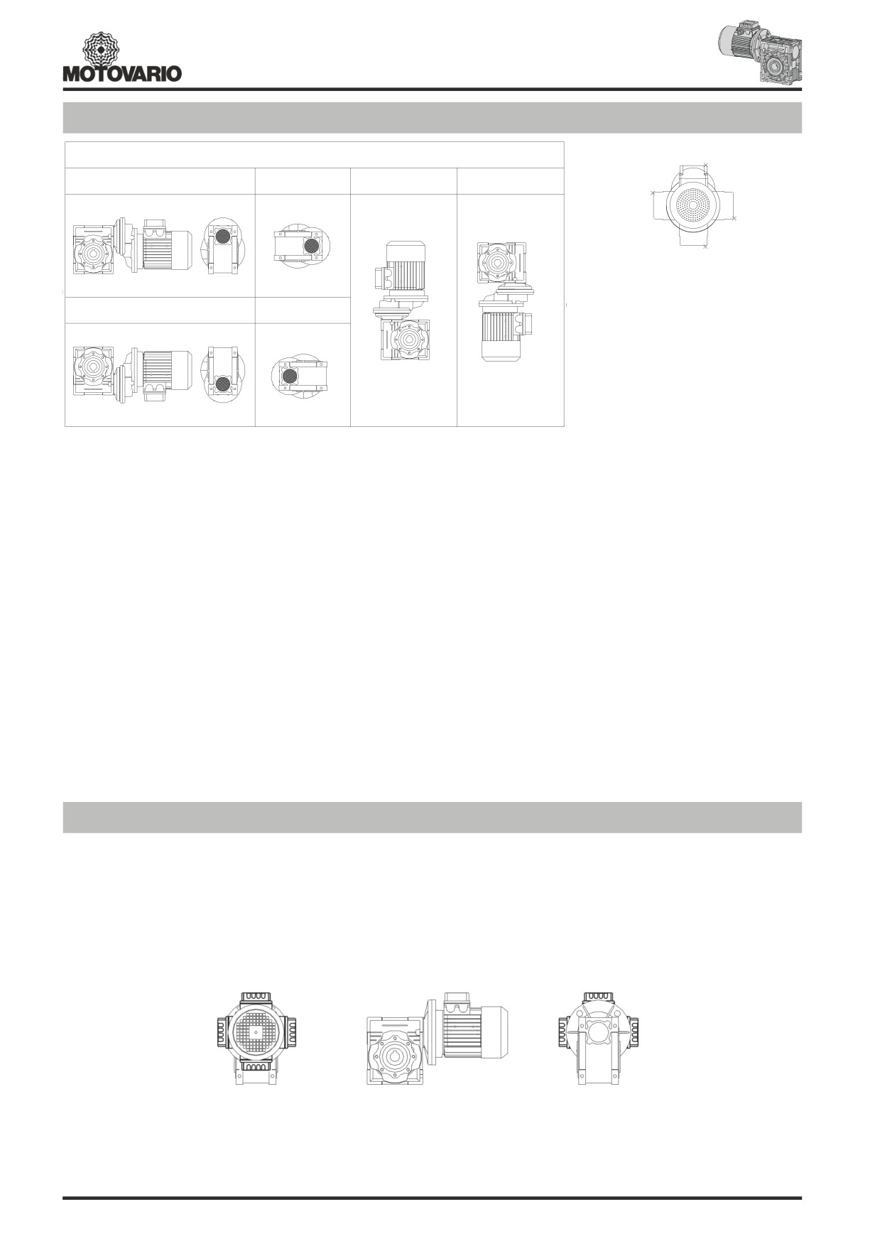
Piazzamento / Mounting positions / Einbaulage / Pos. de montage / Pos. de montaje
PC - NMRV
1
B3
B6
V5
V6
1
4
2
1
3
1
-Posizione morsettiera sempre
riferita alla posizione PC.
B8
B7
-Terminal box position always
refers to PC position.
1
-Die Lage des Klemmenkastens
bezieht sich immer auf PC Stellung.
-La position de la boîte à bornes se
1
réfère toujours à la position du PC.
1
-La posición caja de bornes
siempre se refiere a la posición PC.
1
Per NMRV 030-075 il piazzamento è U e vale per le posizioni B3-B6-B7-B8-V5-V6.
Per NMRV 090-105 il piazzamento B3 vale anche per B6-B7-B8. Piazzamenti V5 e V6 sono singoli.
Per NMRV 110-150 i piazzamenti B3-B6-B7-B8-V5-V6 sono singoli.
For NMRV 030-075 mounting position is U and it is valid for positions B3-B6-B7-B8-V5-V6.
For NMRV 090-105 mounting position B3 is valid also for B6-B7-B8. Mounting positions V5 and V6 must be specified.
For NMRV 110-150 mounting positions B3-B6-B7-B8-V5-V6 must be specified.
Auf NMRV 030-075 ist die Einbaulage U und sie ist gültig für Einbaulagen B3-B6-B7-B8-V5-V6.
Auf NMRV 090-105 ist die Einbaulage B3 gültig auch für B6-B7-B8. Einbaulagen V5 und V6 müssen genau angegeben sein.
Auf NMRV 110-150 müssen die Einbaulagen B3-B6-B7-B8-V5-V6 genau angegeben sein.
Pour NMRV 030-075 la position de montage est U et est valable aussi pour les positions B3-B6-B7-B8-V5-V6.
Pour NMRV 090-105 la position de montage B3 est valable aussi pour les positions B6-B7-B8. Les positions de montage V5 et V6 doivent
être spécifiées.
Pour NMRV 110-150 les positions de montage B3-B6-B7-B8-V5-V6 doivent être spécifiées.
Para NMRV 030-075 la posición de montaje es U y es válida para las posiciones B3-B6-B7-B8-V5-V6.
Para NMRV090-105 la posición de montaje B3 es válida también para las pociones B6-B7-B8. Las posiciones de montaje V5-V6 tienen que
ser especificadas.
Para NMRV110-150 las posiciones de montaje B3-B6-B7-B8-V5-V6 tienen que ser especificadas.
Pos. morsettiera / Pos. of terminal box / Klemmenkastenlage / Pos. du bornier / Pos. caja de bornes
- Nel caso di particolari esigenze specificare in fase di ordine la posizione della morsetteria come da schema.
- In the case of specific requirements, when ordering, specify the position of the terminal box as shown in the diagram.
- Im Falle von Sonderanforderungen ist bei Auftragserteilung die Lage des Klemmenkastens gemäß dem Schema genau anzugeben.
- En cas d’exigences particulières, spécifier, lors de la commande, la position du bornier comme d’après le schéma.
- En caso de exigencias particulares, detallar en el pedido, la posiciónde la caja de bornes según el esquema.
1
1
4
2
2
4
3
3
239