Sany SRT55D Off-Highway Truck. Safety, Operation and Maintenance Manual (2014) - page 4
Controls and Operating
Electronic fuel system injectors are self
compensating and virtually eliminate engine
tune-ups.
Note: Never apply 12V or 24V directly to
terminals on the injector as it will burn out.
Before removing injectors.
3.11.4 Quantum electronic fuel system -
operation
When the 'Stop' light on the dash panel
illuminates, the computer has detected a
major malfunction in the engine that requires
immediate attention. It is the operators
responsibility to shut down the engine to avoid
serious damage.
The machine is equipped with an engine
protection derate system, which records fault
codes when an out-of-range conditions is
found. The Maintenance indicator illuminates
when the engine protection derate system
is initiated. The engine power and speed
will be gradually reduced depending on the
level of severity of the out-of-range condition.
The Maintenance indicator will start to flash
if the out-of-range condition continues to get
worse. The operator MUST shut down the
engine to avoid serious damage' The engine
should not be restarted after it has been shut
down after activation of the engine protection
derate system unless the problem has been
diagnosed and corrected..
Conditions that will cause the amber
Maintenance indicator to come on are; Low
coolant level, High coolant temperature, Idle
validation/throttle pedal switch mismatch, High
intake manifold temperature, Low oil pressure
and High fuel rail pressure.
Whenever the 'Stop', 'Warning' or Maintenance
indicator comes on, the Electronic Fuel
System computer will determine where the
problem is and will store this information in its
memory. If the malfunction is intermittent, the
lights will come on and go off as the computer
3-19
Controls and Operating
senses the changing engine condition.
A special diagnostic data reader (INSITE) is
available that can be plugged into the engine
computer memory to extract information
related to the cause of the problem. Once
the malfunction has been corrected, the
Electronic Fuel System will return the engine
to normal operation. The data reader can now
distinguish between active codes and those
stored in the historic code memory (inactive
codes). Inactive codes can only be viewed
using the data reader. The fault code recorded
in the ECM memory will remain until it is
erased by a technician.
The operator can check for active faults by
turning the ignition key switch to the 'OFF'
position, switching the diagnostic switch
'ON' and then turning the ignition key switch
to position '1'. If no active fault codes are
recorded, all three ('Stop', 'Warning' &
Maintenance) lights will come on and stay
on. If active codes are recorded, all three
lights will come on momentarily. The yellow
('Warning') and red ('Stop') lights will begin to
flash the code of the recorded fault. The fault
codes flash in the following sequence: the
yellow light flashes once, then there is a pause
where both lights are off. Then the numbers
of the recorded fault code flash in red. There
is a pause between each number. When the
number is done, the yellow light flashes again.
e.g. yellow flashes once - pause - red flashes
twice - pause - red flashes three times -
pause - red flashes five times - pause - yellow
flashes once, indicates fault code 235. The
number will repeat in the same sequence until
the system is advanced to the next active fault
code or the diagnostic switch is switched to
the 'OFF' position.
Refer to 'Electronic Fuel System Diagnostic
Codes' table for fault code descriptions.
3.11.5 Electronic fuel system diagnostic
3-20
Controls and Operating
codes
Detection Codes of Electronically Controlled Fuel System
Error Code
Description
Fault lamp
111
ECM Hardware Internal Failure - Mission disabling
Red
112
Timing Actuator - Mechanically stuck
Red
113
Timing Actuator - Component shorted high
Yellow
114
Timing Actuator - Component shorted low
Yellow
115
Engine Speed Sensor - Both signals lost
Red
116
Fuel Timing Pressure Sensor - Component shorted high
Red
117
Fuel Timing Pressure Sensor - Component shorted low
Red
118
Fuel Pump Pressure Sensor - Component shorted high
Yellow
119
Fuel Pump Pressure Sensor - Component shorted low
Yellow
121
Engine Speed Sensor - One signal lost
Yellow
122
Boost Pressure Sensor - Component shorted high
Yellow
123
Boost Pressure Sensor - Component shorted low
Yellow
131
Throttle Position Sensor - Component shorted high
Red
132
Throttle Position Sensor - Component shorted low
Red
135
Oil Pressure Sensor - Component shorted high
Yellow
141
Oil Pressure Sensor - Component shorted low
Yellow
143
Oil Pressure Sensor - Data below normal range
Yellow
144
Engine Coolant Temperature Sensor - Component shorted high
Yellow
145
Engine Coolant Temperature Sensor - Component shorted low
Yellow
151
Engine Coolant Temperature Sensor - Data above normal range
Yellow
153
Intake Manifold Temperature Sensor - Component shorted high
Yellow
154
Intake Manifold Temperature Sensor - Component shorted low
Yellow
155
Intake Manifold Temperature Sensor - Data above normal range
Yellow
221
Ambient Air Pressure Sensor - Component shorted high
Yellow
222
Ambient Air Pressure Sensor - Component shorted low
Yellow
231
Coolant Pressure Sensor - Component shorted high
Yellow
232
Coolant Pressure Sensor - Component shorted low
Yellow
233
Coolant Pressure, Engine Protection - Low coolant pressure
Yellow
234
Engine Speed - Data above normal range
Red
235
Engine Coolant Level - Data below normal range
Yellow
254
Fuel Shutoff Value - Component shorted low
Red
259
Fuel Shutoff Solenoid - Fuel shutoff valve stuck open
Red
261
Fuel Temperature, Engine Protection - Fuel temperature high
Yellow
263
Fuel Temperature Sensor - Component shorted high
Yellow
3-21
Controls and Operating
265
Fuel Temperature Sensor - Component shorted low
Yellow
316
Fuel Pump Actuator - Component shorted high or low
Yellow
318
Fuel Pump Flow - Mismatch between estimated and desired pressures
Yellow
342
ECM Not Calibrated - ECM software mission disabling failure
Red
343
ECM Hardware Failure - Warning non mission disabling
Yellow
346
ECM Software - Read/write, checksum error - Non mission disabling
Yellow
415
Oil Pressure Sensor - Data indicates very low oil pressure
Yellow
422
Engine Coolant Level Sensor Signals - Data invalid
Yellow
423
Fuel Timing Pressure Sensor - In-range failure
Yellow
431
Throttle Position Idle Validation Switch - Invalid
Yellow
Throttle Position Idle Validation Switch - Switch position & throttle percent
432
Yellow
mismatch failure
441
Battery Voltage, Unswitched - Data below normal engine range
Yellow
442
Battery Voltage, Unswitched - Data above normal engine range
Yellow
451
Fuel Pressure Sensor - Component shorted high
Red
452
Fuel Pressure Sensor - Component shorted low
Red
455
Fuel Control Valve - Component shorted high or open
Red
467
Timing Fueling Flow - Mismatch between estimated and desired timing
Yellow
468
Fueling Rail Flow - Mismatch between estimated and desired rail pressure
Yellow
511
Fuel Control Valve - Component shorted low
Red
514
Fuel Control Valve - Actuator mechanically stuck open
Red
524
Alternate Droop Switch Fault
Red
551
Idle Validation Circuit - No voltage detected on both off-idle and idle pins
Red
553
Engine Fueling Pressure Exceeded - Data above normal range
Yellow
554
Fuel Pressure Sensor - In-range failure
Yellow
555
Blowby Pressure, Engine Protection - Blowby pressure high
Yellow
719
Blowby Pressure Sensor - Component shorted high
Yellow
729
Blowby Pressure Sensor - Component shorted low
Yellow
753
Engine Speed Sensor - Engine speed signals do not match
Shutoff
3-22
Controls and Operating
3.12 Steering
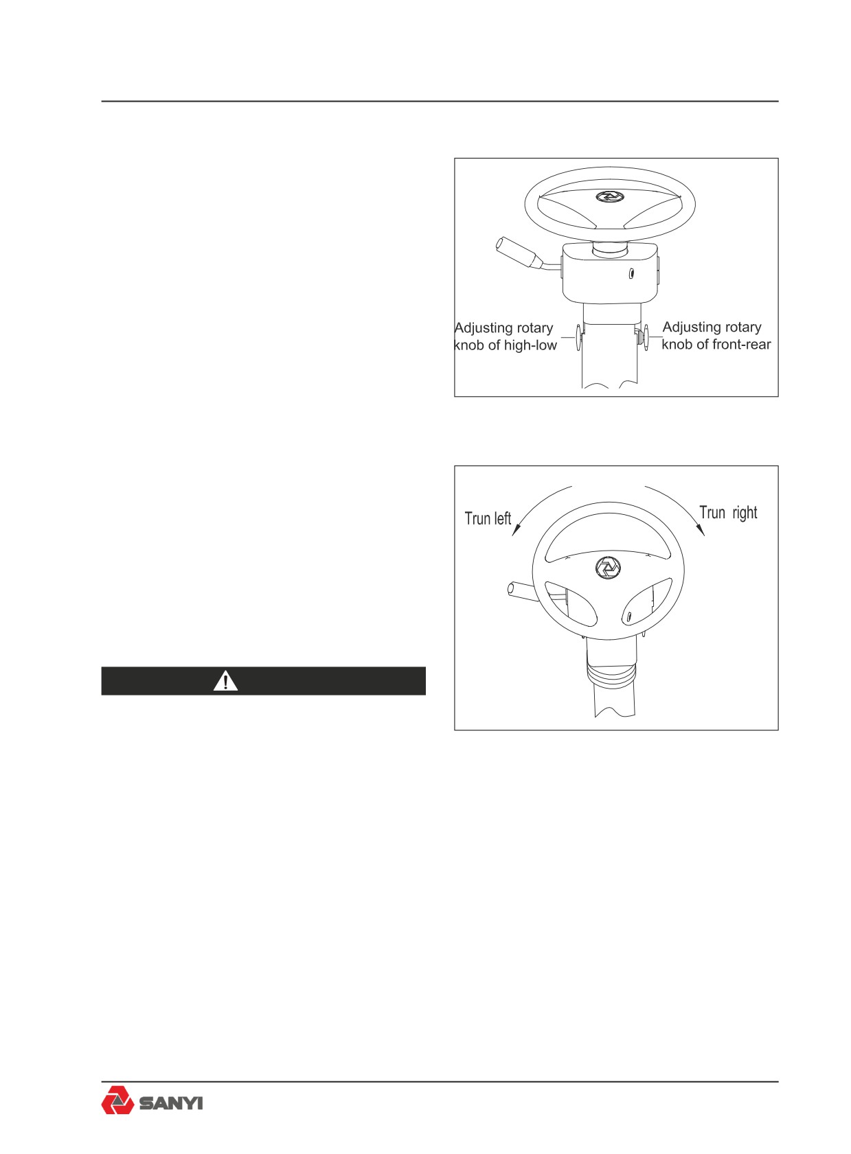
The steering wheel position can be adjusted
as required for the most convenient operating
position. To adjust, pull out adjustment lock
and tilt steering wheel up or down as desired;
release lever to lock adjustment.
The steering system provides full-time
hydraulic power with a continuous-running
pump and a pressurized accumulator. The
accumulator helps maintain a constant flow
of hydraulic power to operate the steering
Fig.3-14
cylinders (Fig.3-14, 3-15).
To steer the front wheels, rotate the steering
wheel in the desired direction to the required
radius of turn. The front wheels will turn only
as the steering wheel is turned and at a rate of
turning directly proportional to steering wheel
speed. The front wheels will stop and hold
position when the steering wheel is stopped.
To return the front wheels to the straight ahead
position or to the opposite direction, turn the
steering wheel in the opposite direction.
warning
In the event of loss of steering pump
output pressure, a fully-pressurize
Fig.3-15
accumulator provides a maximum
of two lock to lock turns of the front
wheels. A red warning light on the
instrument panel illuminates and a
buzzer sounds when steering pressure
falls below 11.5MPa (1660 pound/
in2). If this warning light illuminates,
indicating a loss of steering power, the
machine must be stopped immediately
and no further operation attempted
until the fault is corrected. The
accumulator slowly bleeds down after
engine shut-off to prevent accidental
steering. However, accumulator
3-23
Controls and Operating
pressure should be dissipate after
engine shut-off by turning the steering
wheel in both directions to avoid
accidental steering during bleed down.
Improper steering control unit repair or
hose connections can cause sudden
and forceful steering wheel movement
when engine is started.Keep hands off
steering wheel when starting engine.
3.13 Transmission
3.13.1 CEC2 shift system
The transmission of the truck adopts the
CEC2 (2nd generation commercial electronic
control) shift system. CEC2 is a well designed
computer-controlled automatic shift system,
which integrates functions including automatic
gear-shift, misoperation screening, diagnostic
capabilities, etc., so as to effectively reduce
the fatigue of the driver and make the driver
work safely, easily and simply by focusing on
the road conditions.
Automatic Gear-shift: CEC2 can automatically
select appropriate gear position according
to throttle position, engine speed and truck
speed. Do not move the gear shift handle
frequently during driving. The truck speed can
be controlled through controlling oil supplied
to throttle position by foot pedal. CEC2 can
select economy mode and power mode.
So as to meet the different requirements of
customers.
Reverse Inhibit: Prevents gear selection if
engine is operating at more than 20% throttle.
Hoist interlock pressure switch - The ECU will
shift the transmission from Reverse to Neutral
if the body control lever is moved to the 'Raise'
position.When the body is held in the 'Raise'
position,will prevent to engage Reverse gear.
Body Up Interlock: When the body is raised, the
CEC system will only allow the transmission
3-24
Controls and Operating
to operate in First gear. This feature is only
operational in the normal automatic driving
mode, either power or economy. It is not
activated during the manual mode.
Parking Brake Interlock: If the parking brake
is applied while the transmission is in Neutral,
the CEC2 system will prevent a shift out of
Neutral to protect the brake components. If the
parking brake is applied while the transmission
is in gear, the parking brake interlock will not
function and normal shifts will occur.
Lock-in-gear: The lock-in-gear feature is
designed to protect the transmission from
damage should wheel spinning or lockup occur
due to poor traction or panic braking. The ECU
will delay making a shift for several seconds
and then, if the condition fails to correct itself,
locks in gear and prevents any further shifting.
The Check Trans warning light will come on.
If this occurs, the ECU must be reset before
normal operation may be resumed.
Reset the ECU: if the transmission has
locked in gear because of wheel spinning
or emergency brake, stop the truck, select
neutral, apply the parking brake, and shut
down the engine. Turn off battery main switch,
wait ten seconds, then reconnect the main
switch and restart the engine. Select reverse,
then neutral. The "check transmission" and
"inhibit gear shift" warning light should go off.
Cold Weather Starts: During cold weather
starts, if the transmission temperature is below
-24
℃ (-10°F), The "check transmission" and
"forbid gear shifting" warning light will come
on, and the ECU will keep the transmission
at neutral gear. Between -24° C (-10°F) and
-7 ℃ (19°F) ,the warning light will go out and
the ECU will only permit operation in First or
Reverse gears. Above -7
℃ (19°F), normal
operation will be permitted.
3-25
Controls and Operating
warning
Before any welding is done on a
machine equipped with a CEC shift
system, disconnect battery equalizer
ground cables, battery cables from
terminal posts (ground cable first),
battery equalizer positive cables
and electrical connections at the
ECU to avoid damage to electrical
components. Turn off ignition key
switch to isolate the batteries before
disconnecting any components.
The standard procedure for raising the
body must still be adhered to.
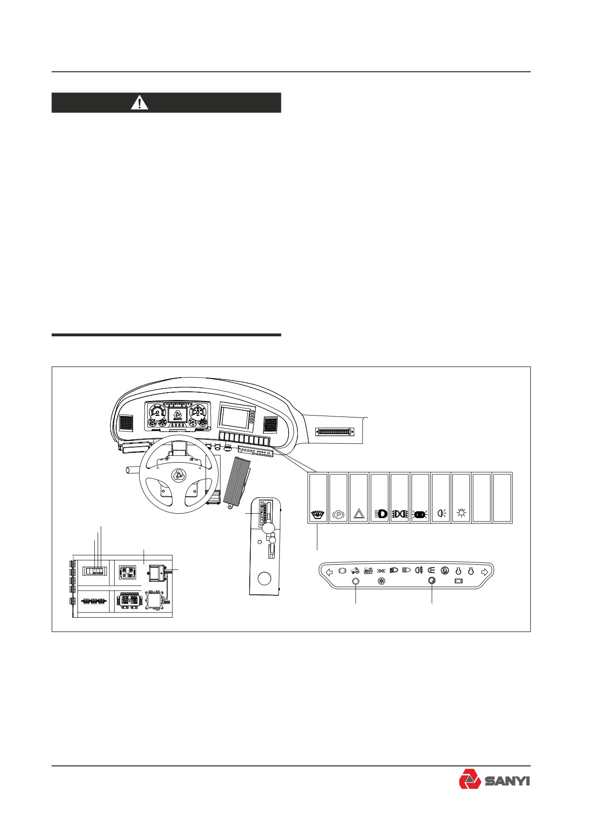
3
P
7
6
5
2
4
1
P
!
!
9
8
Fig.3-16
1.Electronic Control Unit (ECU)
6. Stalling Detection Switch
2.Control Box
7.Idling Adjustment Switch
3.Gear Shift Selector
8.Transmission overspeed indicator
4.Mode Selection Switch
9. Transmission fault indicator
5.Diagnosis switch
3-26
Controls and Operating
3.13.2 Introduction and operation
(1) Electronic Control Unit (ECU) - The ECU
contains an electronic microcomputer.It
receives information in the form of electronic
signals from switches and sensors, processes
the information, and sends electronic signals
to the appropriate solenoids which control the
transmission.
(2) Control Box -- Contains fuses \ relays and
ECU.
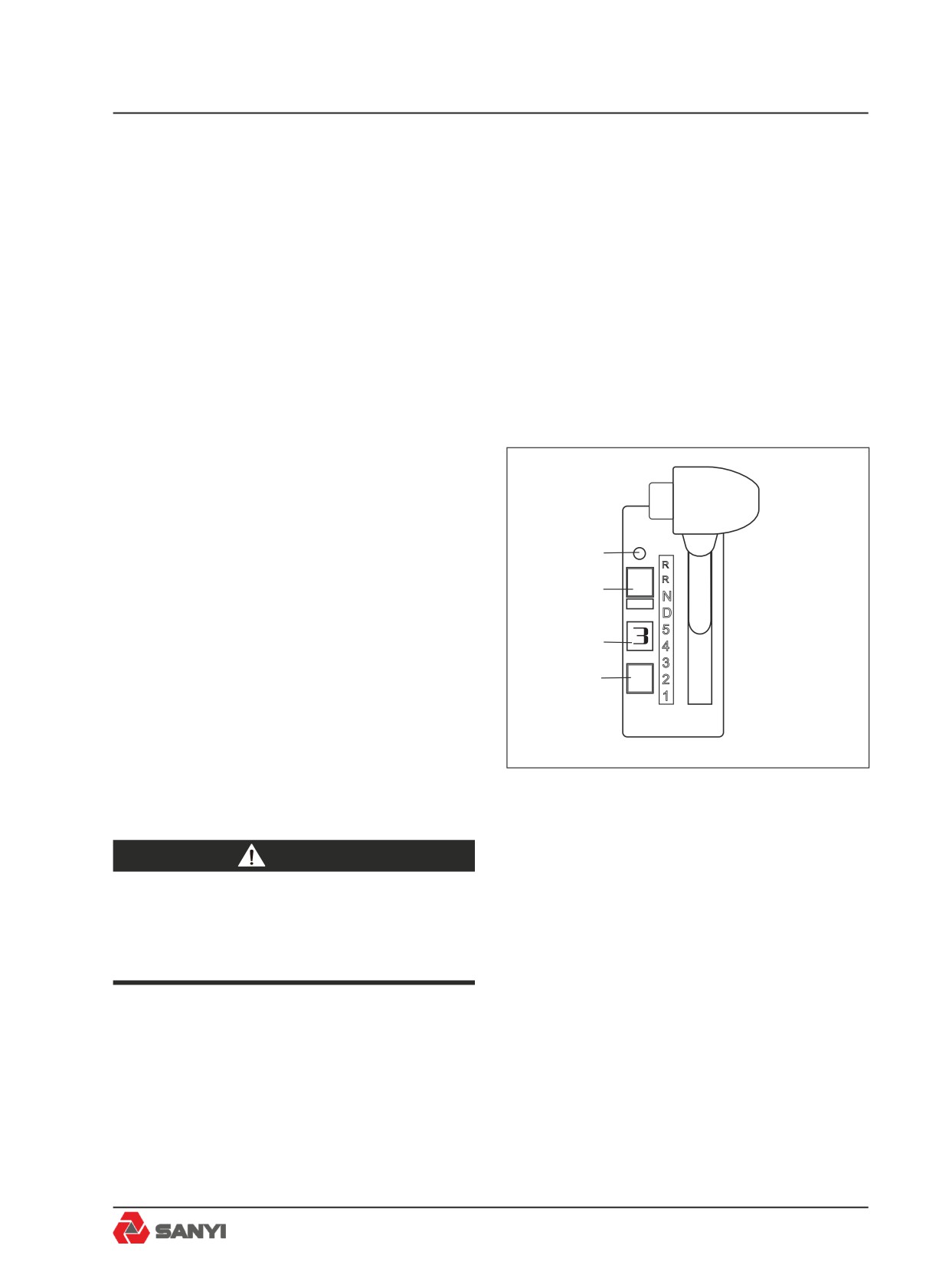
(3) Gear Shift Selector -- The shift selector is
a remote mounted lever type. The gear shift
selector is connected to the ECU by a wiring
harness. The shift lever has 5 forward ranges
and 2 reverse ranges, as well as a neutral
position.
The shift selector has a single digit LED
4
2
display, that during normal operation will
MODE
1
3
display the gear selected. Diagnostic
information can be displayed on the single
digit LED display by pressing the diagnostic
2
display button. There is a hold override button
1
that must be pressed when shifting between R,
N and D. The hold override button is released
when desired selector position is reached. The
selector lever can move freely between D and
the number ranges without pressing the hold
Fig.3-17
override button. (Refer to fig.3-17)
warning
Do not allow the vehicle to coast in
Neutral. This practice can result in
severe transmission damage.
The transmission upshifts and downshifts
automatically between first range and the
highest range selected on the range selector
in direct response to throttle position, engine
speed and transmission output speed.
When Reverse is selected the reverse alarm
sounds and the reverse light illuminates at
3-27
Controls and Operating
the rear of the vehicle. This feature warns
personnel to the immediate rear of the vehicle
that the operator has shifted to reverse.
When drive 'D' is selected, the transmission
automatically upshifts and downshifts through
all six forward ranges as required by loads and
travel speeds. Selecting a lower range (4th,
3rd etc.) limits the highest range to which the
transmission will automatically upshift.
If a lower range is selected while moving
forward, the transmission automatically
downshifts sequential to the selected lower
range at maximum controlled engine speeds.
Downshifts will not occur until vehicle is
slowed by use of the service brakes and/or
retarder.
When shifting from neutral to start from a
standstill, or to reverse direction, decelerate
the engine to idle speed. To move forward,
select drive 'D' and accelerate the engine to
the vehicle load and speed requirements. The
transmission will automatically upshift from 1st
through 5th ranges as travel speed increases.
With the throttle fully depressed, and the
mode selection switch in the Power position,
the transmission upshifts to the next higher
range when the engine attains maximum
rated speed, since maximum power train
output is needed under this condition. At lower
throttle settings where minimum power train
performance is required, the transmission will
upshift to the next higher range at less than
maximum rated engine speed.
Upgrades or soft spots might slow travel
speed, even at full throttle, requiring
transmission downshifts to maintain maximum
powertrain performance. When this occurs,
the transmission downshifts automatically.
Shift the transmission to the next lowest range
if transmission 'Hunting' or 'Shift Cycling'
occurs.
When temporarily stopped, such as for
yielding the right-of-way to a loaded vehicle,
3-28
Controls and Operating
the transmission can be left in the selected
range and the vehicle held stationary with the
service brakes.
However, when stopped for a more extended
period with the engine left running, shift the
transmission to neutral to avoid unnecessary
heat buildup and apply the parking brake.
warning
Always select Neutral and apply the
parking brake before leaving the
operator’s seat.
(4) Mode selection switch - Gives the option
to select between transmission 'POWER' and
'ECONOMY' shift schedules.
Note:The transmission must be in Neutral
before the switch will function; otherwise,this
practice can result in transmission damage.
The transmission torque converter is equipped
with a lockup clutch which, when engaged
by the ECU, locks the converter pump and
turbine together as a single unit and allows
power to be transmitted mechanically from
the engine directly to the transmission gearing
on a 1 to 1 ratio. When the lockup clutch is
disengaged, the torque converter acts as a
fluid coupling, multiplying torque when engine
speed is significantly higher than transmission
output shaft speed.
When the Mode Selection Switch is in the
'POWER' position, the ECU controls operation
of the lockup clutch according to signals
received by the throttle position sensor (giving
engine speed as a percent of throttle), the
transmission output shaft speed sensor,
and range selector. The ECU may delay
application of the lockup clutch and allow
torque multiplication by the torque converter to
take place until a balance is achieved between
engine speed and transmission output shaft
3-29
Controls and Operating
speed before activating the lockup clutch.
Power versus Economy Mode
The POWER mode is designed for
applications involving heavy loads and hilly
duty cycles where performance rather than
fuel economy is of prime importance.
The ECONOMY mode is designed for
applications involving lighter loads and level
duty cycles or where fuel economy is more
important than performance.
In the ECONOMY mode, the ECU controls
operation of the lockup clutch with atimed,
preprogrammed schedule where in Second
through Sixth gears the lockup clutch is
disengaged only long enough to allow the
torque converter’s fluid coupling to absorb
shift shock. Otherwise, the lockup clutch is
engaged and no torque multiplication takes
place in Second through Sixth gears.
(5).Diagnosis switch -- This switch is provided
for the professional service technician of the
engine, and is used to retrieve fault codes of
the engine. By default, this switch is opened
by pressing its bottom (lower) part.
(6) Output stalled switch
-- This switch
is provided for the professional service
technician of the transmission, and is used to
test the matching between the transmission
and the engine output torque. By default, this
switch is opened by pressing its top (upper)
part.
(7)Idling Adjustment Switch-This switch
is provided for idling adjustment function,
operator can use to increase or decrease
idling.
(8) Engine Overspeed Light (Red) -- Illuminates
when the transmission ECU senses engine
speed above 2350 r/min.
(9) Check Trans Warning Light(Red) --
Illuminates to alert of a minor fault in the
transmission shift system or abnormal
transmission temperature. The warning light
will come 'On' when the ignition keyswitch
3-30
Controls and Operating
is turned to position '1' to provide a bulb
and system check and should go 'Off' a few
seconds after the engine is started and the
transmission oil pressure rises.
The check trans warning light will come 'On'
during operation if the ECU has detected
a minor fault in an electrical component or
abnormal transmission oil temperature. If
transmission oil temperature is too high, stop
the machine, select Neutral (N), and increase
engine speed to allow a greater flow of oil
to the oil cooler until oil temperature drops
to normal operating range. In most cases, a
minor fault triggering the check trans warning
light will not prevent normal operation from
continuing but, depending on the nature of
the problem, the ECU could take action to
protect the transmission from damage, such
as preventing operation in high gear ranges.
If the ' check trans ' warning light comes on,
have the problem diagnosed and corrected at
the earliest opportunity.
warning
Do not operate engine for more
than 30 seconds at full throttle with
transmission in gear and output stalled
as this will result in severe overheat
damage to the transmission.
3.13.3 General transmission operation
Watch for wide deviations from normal
readings on the transmission oil
temperature gauge during truck operation. If
the transmission oil
temperature gauge, on vehicles which do not
have a transmission retarder fitted, shows
oil temperature consistently rising above
the green zone (65 - 135°C; 149 - 275°F)
under normal operating conditions; check
for external causes. If none are evident
3-31
Controls and Operating
shift to Neutral (N) and operate the engine
at 1200 - 1500 r/min. If the transmission
oil temperature does not decrease into the
green zone within 2 or 3 minutes, the cause
of the overheating should be corrected before
the machine is operated further. Watch the
oil temperature gauge when operating on
upgrades, also. If the oil temperature goes
into the red zone (165 -176°C; 329 - 350°F),
select the range which will limit upshifts to
the highest range in which the transmission
will operate within the normal temperature
range. If upshifting must be consistently
limited to ranges lower than normal for the
loads and the grades encountered to prevent
overheating the transmission oil, the causes
should be determined and corrected. On
trucks fitted with a transmission retarder, it is
permissible to operate with the gauge showing
in the yellow zone, during operation of the
transmission retarder, but the operation can
not last for more 3 minutes, or damage to the
transmission may result.
3.13.4 Retrieving diagnostic codes
Diagnostic fault codes can be retrieved from
the CEC2 system using the gear shift selector
or by plugging in the diagnostic data reader
(DDR). To obtain diagnostic codes using the
gear shift selector::
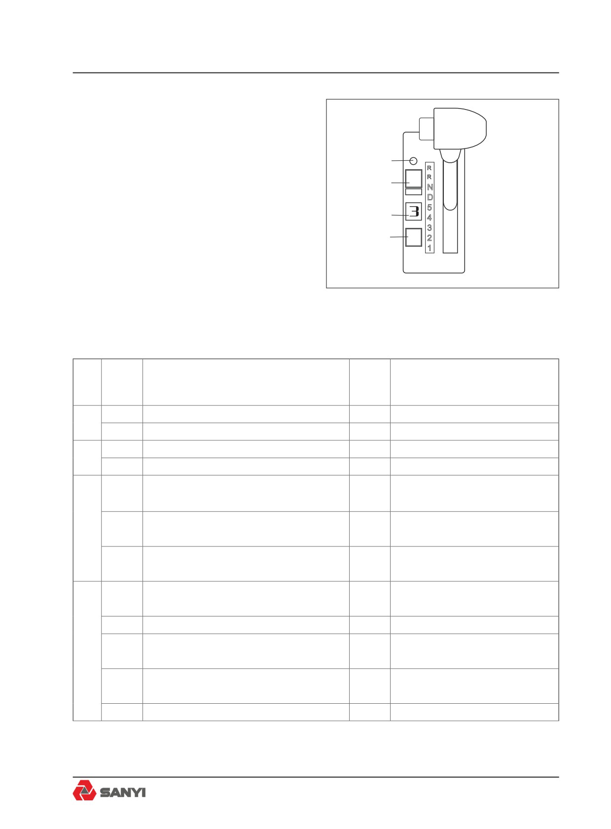
※Check transmission warning light on dash
will illuminate when ECU detects a fault.
※Stop truck and select 'Neutral'.
※Press diagnostic button (1) on gear shift
selector. Display (2) on gear shift selector will
flash one digit at a time.
※Display starts with code position D1, D2,
etc, followed by the two digit main code, then
the two digit subcode.
※To advance to the next code, press the
mode button (3). Up to five codes can be
stored.
※Active codes are indicated by illumination of
3-32
Controls and Operating
the mode light (4).
4
3.13.5 Clearing diagnostic codes
2
MODE
1
To clear active codes, press and hold mode
3
button (3) for 3 to 5 seconds.
To clear inactive codes, press and hold mode
2
button (3) for 8 to 10 seconds.
1
To exit diagnostic mode, press diagnostic
button (1). Refer to table for diagnostic code
description.
Fig.3-18
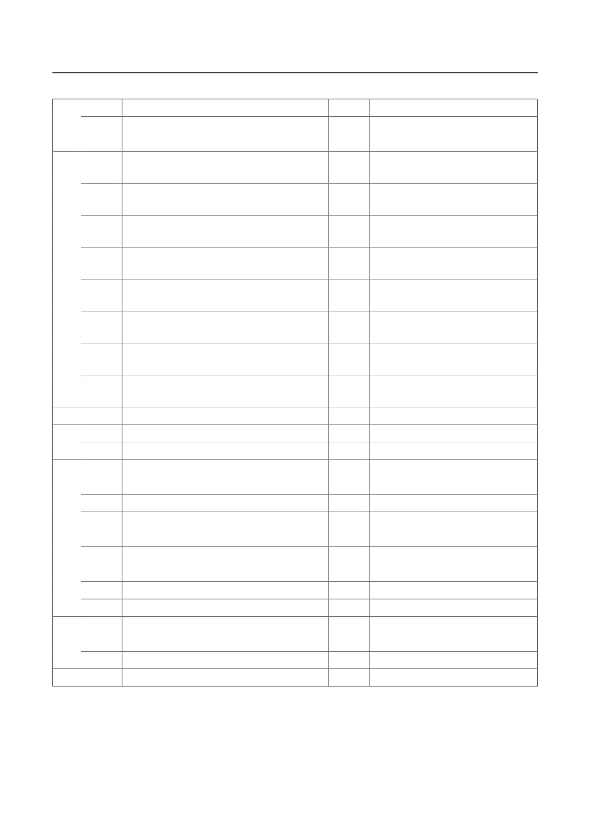
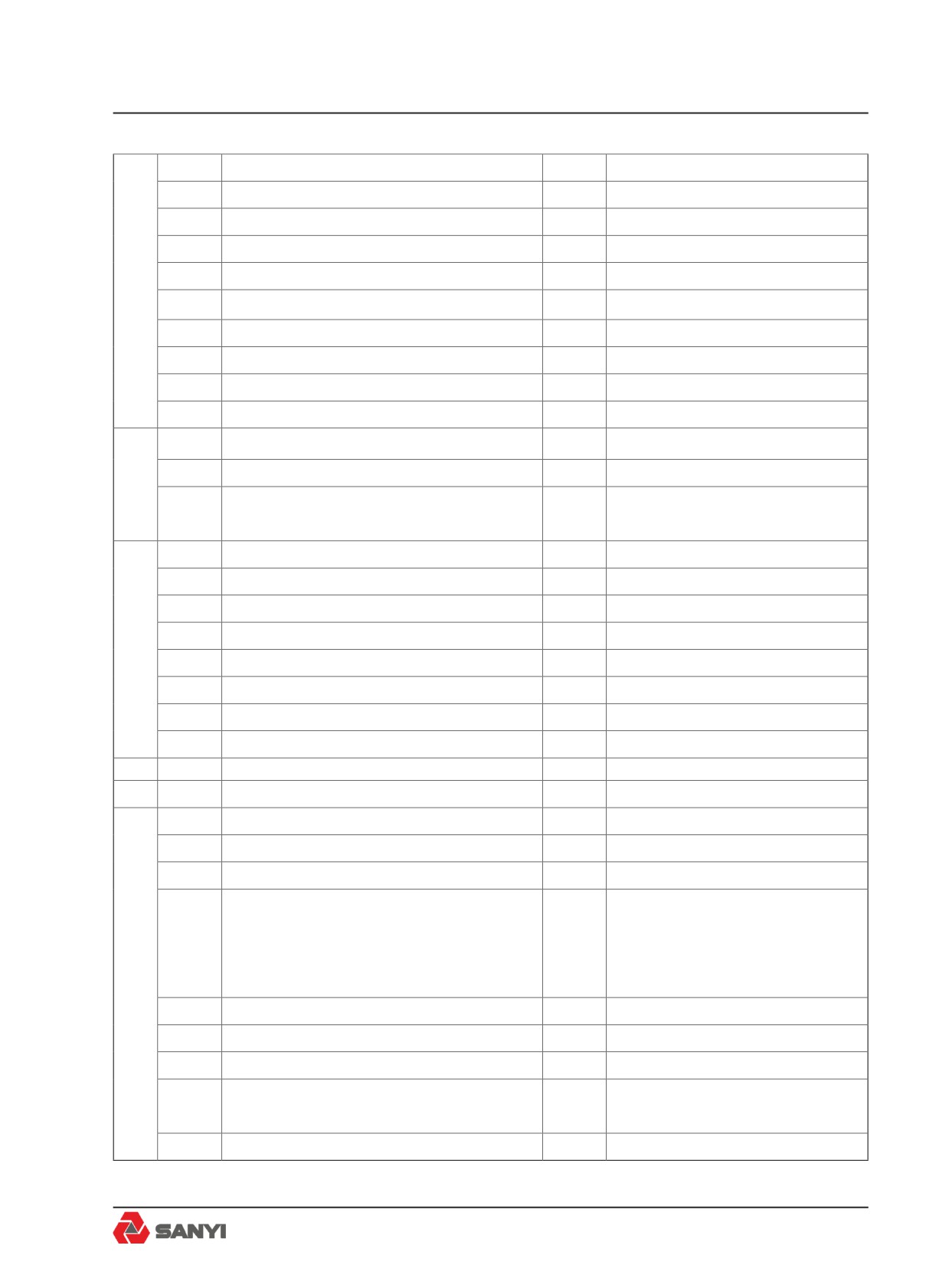
3.13.6 Diagnostic codes
Check
Main
Sub
Inhibited Operation
Description
Trans
code
Code
Description
Light
12
ECU input voltage, low
Yes
DNS
13
23
ECU input voltage, high
Yes
DNS
12
Throttle position sensor, failed low
Yes
Use throttle default values
21
23
Throttle position sensor, failed high
Yes
Use throttle default values
Engine speed sensor reasonableness
14
Yes
Use default engine speed
test
Turbine speed sensor reasonableness
22
15
Yes
DNS, lock in current range
test
Output speed sensor reasonableness
16
Yes
DNS, lock in current range
test
Hold in last valid direction. May
12
Primary shift selector or RSI link fault
Yes
cause “cateye” display
13
Primary shift selector mode function fault
No
Mode change not permitted
Secondary shift selector or RSI link
Hold in last valid direction. May
23
14
Yes
fault
cause “cateye” display
Secondary shift selector mode
15
No
Mode change not permitted
function fault
16
Shift Selector display line fault
Yes
None. May cause “cateye” display
3-33
12
Sump fluid temperature, cold
Yes
DNS, lock-to-range
24
No upshifts above a calibration
23
Sump fluid temperature, hot
Yes
range
Output speed sensor, detected at 0 output
11
Yes
DNS, lock in current range (1st)
rpm, 1st
Output speed sensor, detected at 0 output
22
Yes
DNS, lock in current range (2nd)
rpm, 2nd
Output speed sensor, detected at 0 output
33
Yes
DNS, lock in current range (3rd)
rpm, 3rd
Output speed sensor, detected at 0 output
44
Yes
DNS, lock in current range (4th)
rpm, 4th
25
Output speed sensor, detected at 0 output
55
Yes
DNS, lock in current range (5th)
rpm, 5th
Output speed sensor, detected at 0 output
66
Yes
DNS, lock in current range (6th)
rpm, 6th
Output speed sensor, detected at 0 output
77
Yes
DNS, lock in current range (7th)
rpm, 7th
Output speed sensor, detected at 0 output
88
Yes
DNS, lock in current range (8th)
rpm, 8th
26
00
Throttle source not detected
No
Use throttle default values
12
Sump fluid temperature sensor failed low
Yes
Use default value of 93°C (200°F)
33
23
Sump fluid temperature sensor failed high
Yes
Use default value of 93°C (200°F)
Factory calibration compatibility number
12
Yes
DNS, SOL OFF
wrong
13
Factory calibration fault
Yes
DNS, SOL OFF
Use previous location, or factory
14
Power off fault
Yes
34
calibration
Use previous location, or clear
15
Diagnostic queue fault
Yes
diagnostic queue
16
Real time fault
Yes
DNS, SOL OFF
17
Customer modifiable constants fault
Yes
DNS, SOL OFF
Power interruption (code set after power
None (hydraulic default during
00
No
35
restored)
interruption)
16
Real time write interruption
Yes
DNS, SOL OFF
36
00
Hardware/software not compatible
Yes
DNS, SOL OFF
3-34
12
General solenoid failure - F
Yes
DNS
13
General solenoid failure - K
Yes
DNS, Inhibit lockup
14
FGeneral solenoid failure - B
Yes
DNS, Inhibit Reverse
15
General solenoid failure - G
Yes
DNS
16
General solenoid failure - E
Yes
DNS
45
21
General solenoid failure - H/J
Yes
Turn off trim boost J, DNS H
22
General solenoid failure - A
Yes
No action taken
23
General solenoid failure - D
Yes
DNS
24
General solenoid failure - I
Yes
No action taken
26
General solenoid failure - C
Yes
DNS
21
Hi side overcurrent, H/J solenoid
Yes
Turn off H/J solenoid, DNS
26
Hi side overcurrent, C, D, E solenoid circuit
Yes
Turn off C, D, E solenoids
46
DNS. Turn off A, B, F, G, I, K
27
Hi side overcurrent, A, B, F, G, I, K
Yes
solenoids
11
Range verification ratio test, 1st
Yes
DNS
22
Range verification ratio test, 2nd
Yes
DNS
33
Range verification ratio test, 3rd
Yes
DNS
44
Range verification ratio test, 4th
Yes
DNS
56
55
Range verification ratio test, 5th
Yes
DNS
66
Range verification ratio test, 6th
On
DNS
77
Range verification ratio test, 7th or R1
Yes
DNS
88
Range verification ratio test, 8th or R2
Yes
DNS
65
00
Engine rating too high
Yes
DNS, Lock-in-neutral
66
00
Serial communications interface fault
No
Use default throttle values
27
ECU, inoperative A, B, F, G, I, K solenoid
Yes
DNS, SOL OFF
28
ECU, inoperative H/J solenoid
Yes
DNS, SOL OFF
29
ECU, inoperative C, D, E solenoid
Yes
DNS, SOL OFF
Reset ECU, shutdown ECU on 2nd
ECU, Computer Operating Properly (COP)
occurrence (power loss; hydraulic
33
Yes
fault
defaults). May cause “cateye”
display or all segments blank display
69
34
ECU, EEPROM, fault
Yes
DNS, SOL OFF
35
ECU, EEPROM, fault
Yes
Reset ECU
39
Communication chip addressing error
Yes
Use defaults for J1939 data
GPO 1-8 and reverse warning
42
SPI output failure
No
inoperable
43
SPI input failure
Yes
DNS, lock-in-range
3-35
Controls and Operating
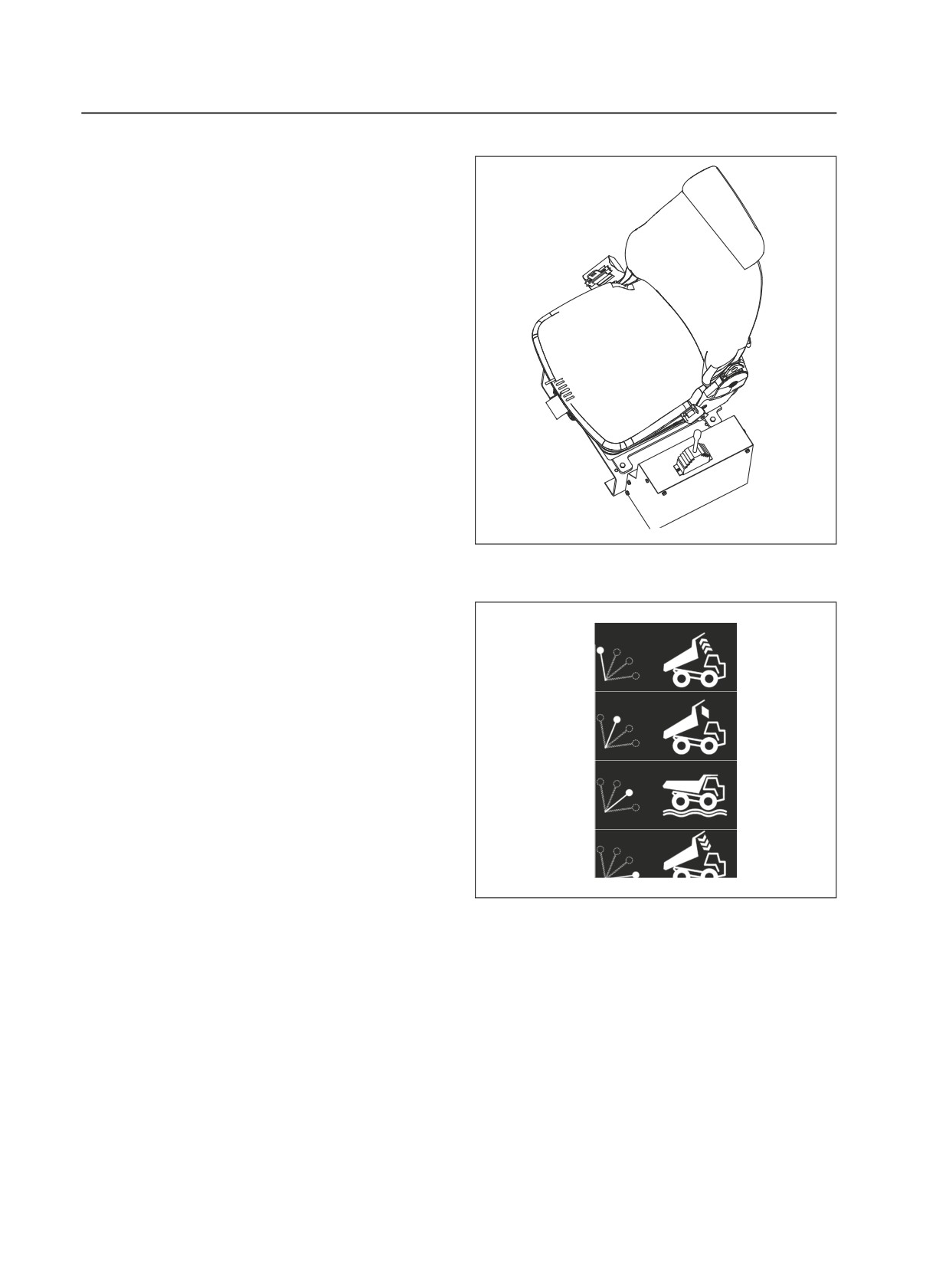
3.14 Body Control
Operate the hoist lever(see Fig. 3-19) the left
of operator’s seat to raise or lower body. The
four operating positions of the lever from front
to rear are as follows :
HOIST -This position directs oil to extend the
body hoists and raise the body.
When released, the lever will be spring-
returned to the 'HOLD' position.
HOLD - Push the lever to this position while
the body is being raised and lowered to stop
movement and hold the body to the expected
height. The lever will be locked and kept at “
HOLD” position during releasing.
FLOAT - While the body drops via gravity, the
lever will be moved to and kept at this position
Fig.3-19
until the body will be operated again. The lever
shall be kept at “float” position during the truck
is in motion .
LOWER -This position provides hydraulic force
HOIST
to power-down the body. The body raised to
the highest position needs to be dropped with
hydraulic power, i.e., the lever shall be pushed
HOLD
to this position; when the body is dropped to
a certain height, it will drop via gravity. Then,
release lever and the lever will be moved to
FLOAT
the float position via spring which inside of the
valve (see Fig. 3-20).
LOWER
1. Hoist
Preparation:
(1) Run the engine in idling speed;
Fig.3-20
(2) Make sure the rear wheels are on the firm
level ground;
(3)Shift the transmission to Neutral and hold
the machine stationary by applying the brakes
with the Parking-Emergency brake button.
Lifting:
(1) Pull the lever backward to the “Raise”
position, hold the lever and accelerate engine
to raise body;
(2) Moves the raise lever to "hold" position
when the body is required to stay at a certain
3-36
Controls and Operating
height;
(3) Decelerate the engine when the last stages
of the body hoists begin to extend to slow the
raising speed as the hoists approach their
maximum extensions;
(4) Pull the lever to “HOLD” position when the
body is raised to the desired height.
WARNING
Drain the pressure form the pilot valve
before while repairing the raise system and
its control system .
Method: Turn off the engine, operate the
RAISE lever for about 15 times in two
directions, to drain the pressure oil form
the pilot valve.
2. Lower
Lowering the body:
(1) Move the handle to “float” position; then
the body will lower to the frame via gravity;
(2) If the body is required to stay at a certain
height, the handle shall be moved to “HOLD”
position;
(3) If the body does not begin to lower
by its own weight, such as after dumping
downgrade, move the control lever all the way
forward to the 'LOWER' position and power
the body downward until it begins lowering
by gravity. Then move the lever to 'FLOAT'
position in the specially situation.
Caution : Make sure that the body is
completely lowered and the control lever is
in 'FLOAT' before releasing the brakes and
moving the machine.
3-37
Operating the Truck
4 OPERATING THE TRUCK
4.1 Pre-Starting Inspection
※ Before the engine is started ensure the
machine is ready for operation.
※ The machine should be in a level position to
permit accurate checking of fluid quantities in the
engine and other components.
※ Make sure parking brake is applied and block
wheels securely to prevent accidental movement
of the machine while checking component levels.
※ Test all lights, warning signals, controls and
instruments for proper operation.
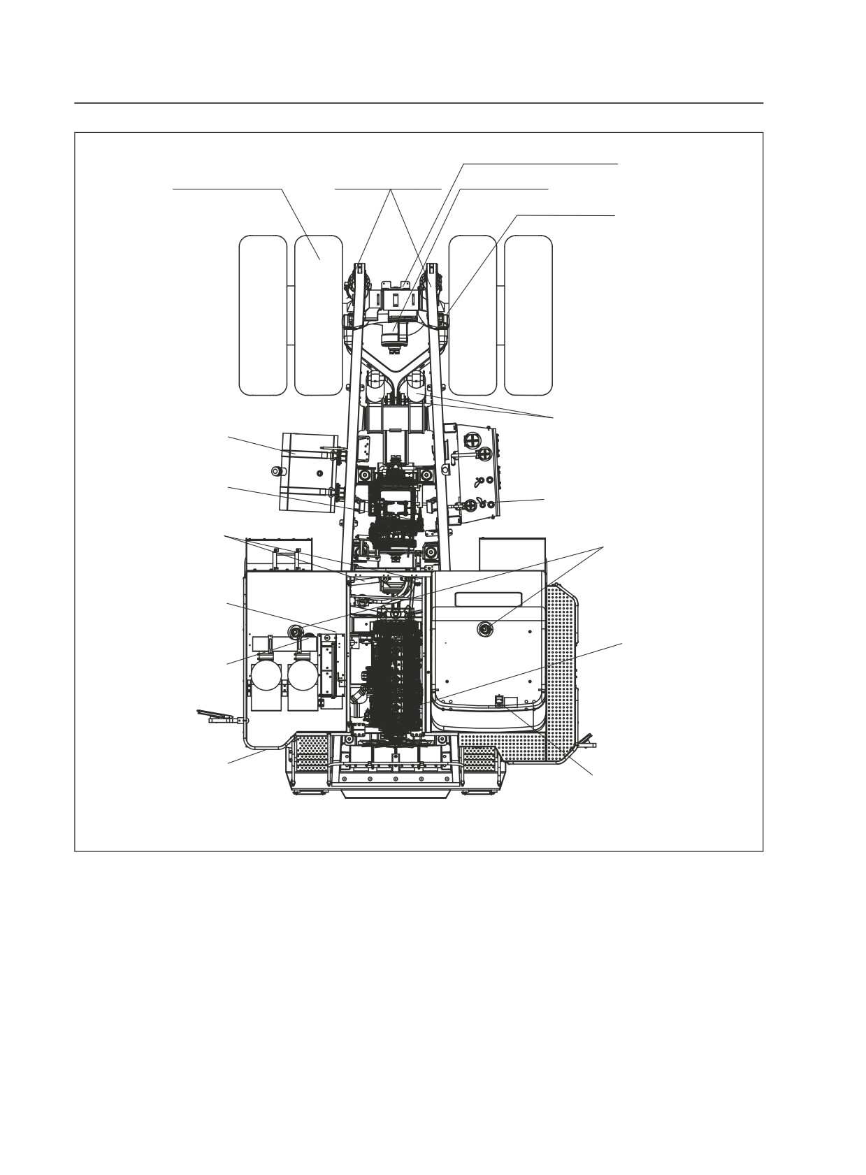
※ Walk around the machine and carry out the
Inspections and Component Checks described
in the drawing opposite and on the following
pages.
4-1
Operating the Truck
Rear lamp assembly Check for leakage
REAR RIDE CYLINDERS
and normal working
WHEELS AND TYRES Check condition,
Check for debris leaks and
inflation, nuts and for damaged rims
damage. Check height
DIFFERENTIAL Check for leaks
DISC BRAKE ASSEMBLIES Check for leaks
BODY CYLINDERS Check for debris,
leaks and damage. Check lines for
FUEL TANK Check fuel level.
wear and leaks.
Ensure fuel tank is full.
Check that tank is securely mounted.
TRANSMISSION Check oil level.
Check for leaks
Hydraulic oil tank Check oil level.
Check for leaks
STEERING CYLINDERS Check for
debris, leaks and damage.
FRONT RIDE CYLINDERS
Check lines for wear and leaks
Check for debris, leaks and
damage. Check height
BRAKE ACCUMULATORS
Check for leaks.
ENGINE Check oil level.
Check liquid level of expan-
Check for leaks
sion water tank and leakage
Front lamp assembly Check
for damage and normal working
CAB, PLATFORM AND STEPS Check
for cleanliness. Check seat belts.
Fig. 4-1
4-2
Operating the Truck
4.2 Check Of Each Component
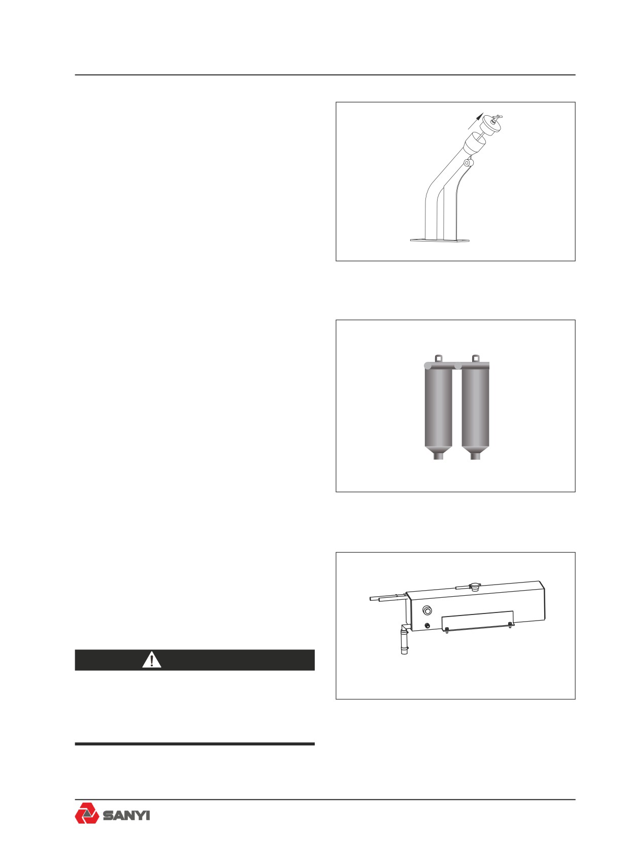
1. Engine
With the engine off, check oil level. The oil
level should be between the lower and upper
marks on the dipstick. Add oil if low (see Fig.
4-2).
Fig. 4-2
2. Fuel filters
Drain sediment and water from sump until fuel
runs clear (see Fig. 4-3).
Fig. 4-3
3.Radiator header tank
Check coolant level. Add if low. (see Fig. 4-4).
In subfreezing temperatures, be sure that the
coolant contains sufficient antifreeze.
WARNING
Press button in centre of cap to
bleed pressure before removing cap
Fig. 4-4
completely. Fill to bottom of filler neck.
4-3
Operating the Truck
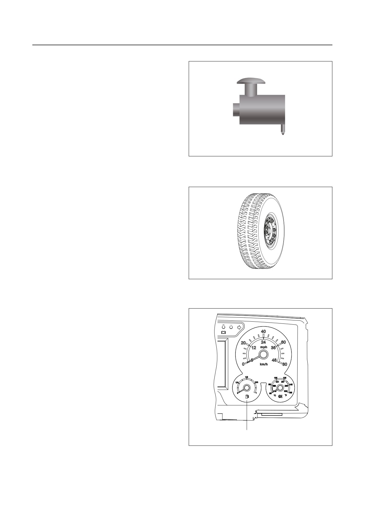
4. Air Cleaner vacuator valve(s)
Check for proper operation. Clean if Required
(see Fig. 4-5).
Fig. 4-5
5. Tyres
Carefully inspect all tyres for cuts, bruises,
or other damage and proper inflation for the
loads to be carried. Inflate all tyres to the
recommended pressure while cold (see Fig.
4-6).
Fig. 4-6
!
6. Fuel level gauge
Check fuel level. Tank should be filled at end
of each shift to prevent condensation(see Fig
4-7).
Fuel gauge
Fig 4.7
4-4
Operating the Truck
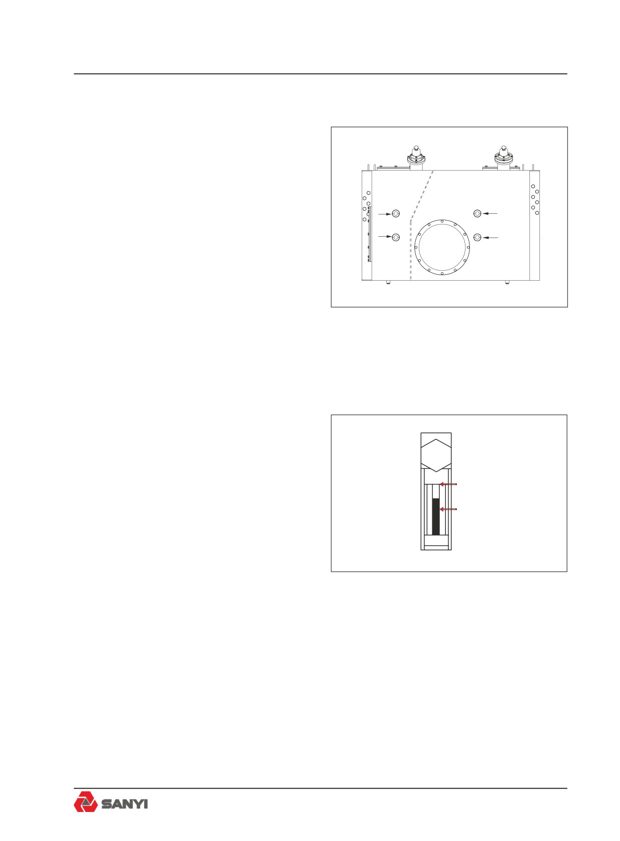
7. Body and disc brake cooling tank - cold
oil level
The bottom sight gauge should show full. Add
fluid, if low (see Fig. 4-8)
steering oil pointer
8. Steering and braking tank - cold oil level
lifting oil pointer
up oil pointer
up oil pointer
With the engine off, turn the steering wheel
back and forth to dissipate any pressure in the
down oil pointer
down oil pointer
steering accumulator. Oil should be showing in
the middle sight gauge. Add fluid, if low (see
Fig. 4-8).
Fig. 4-8
9. Transmission - cold oil level
This check is made only to determine if the
transmission contains sufficient oil for safe
starting. Make sure there is some oil showing
Full
on the sight gauge before starting the engine.
1/2 Oil level
Add oil if low (see Fig. 4-10).
Fig. 4-9
4-5
Operating the Truck
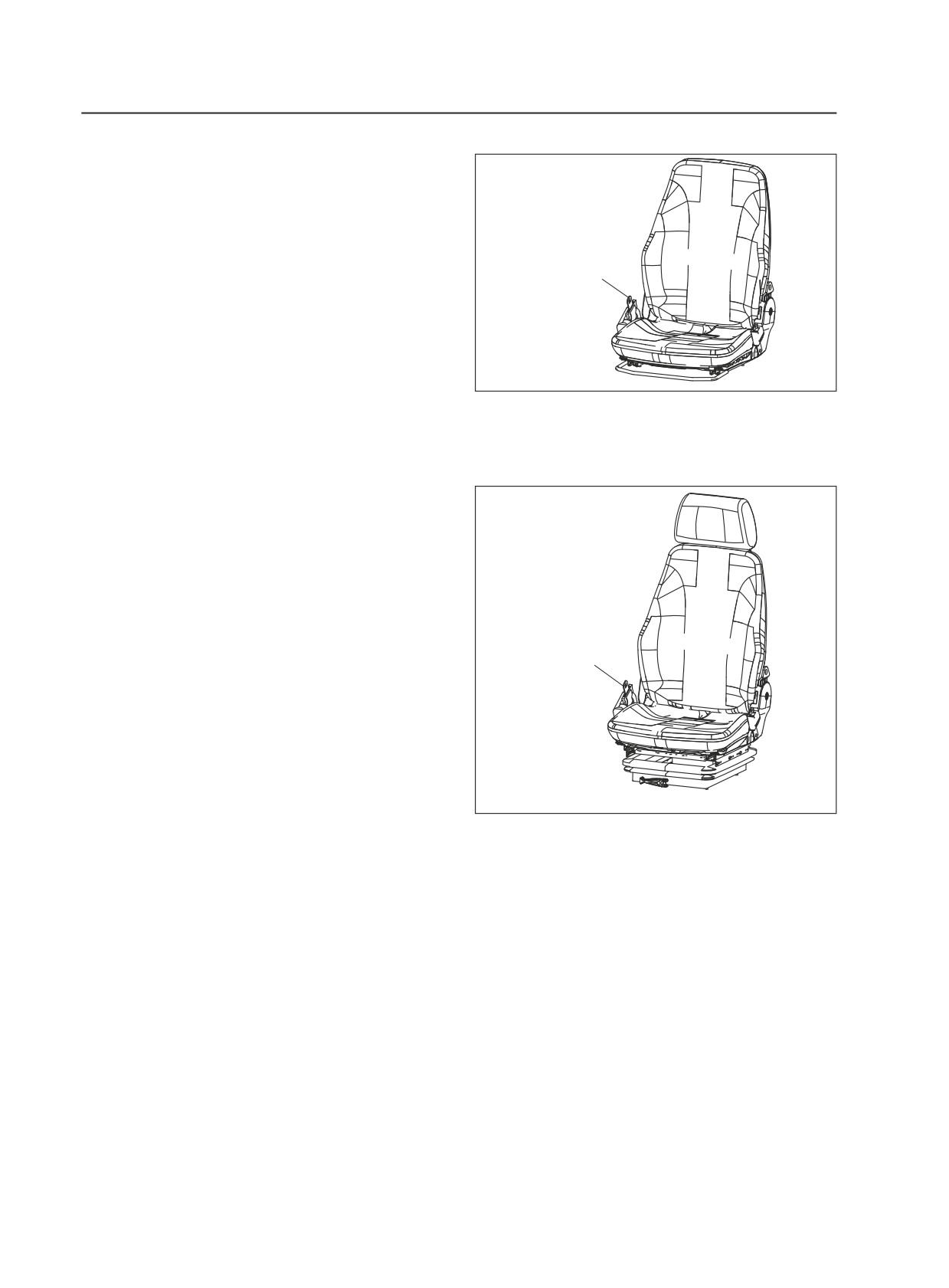
10. Seat and seat belts
Adjust the seat position and lap belt as
required to allow complete machine control
Safety belt
at all times with minimum fatigue. Make sure
the seat belt does not restrict movement for
proper machine operation (see Fig. 4-10 and
4-11).
Fig. 4-10
Safety belt
Fig. 4-11
4.3 Engine Operation
Note: The electronic controlled engine will
override the electronic foot pedal position
until the engine is warmed up to the correct
operating temperature. The engine MUST
be started with foot 'OFF' the electronic foot
pedal.
Do not place engine under FULL LOAD at
FULL SPEED IMMEDIATELY after starting.
4-6
Operating the Truck
ALWAYS allow the engine to fully circulate
lubricant and warm up gradually before
operating at full speed and full load.
Operate engine at top rated speed when
maximum power is needed for the load.
NEVER idle the engine more than 5 minutes
at a time; shut it off.
If any gauge operates outwith its normal
operating range or a warning light illuminates,
shut engine down immediately and report to
service or maintenance personnel.
Turn off the engine if the “stop”, “warning”,
and “maintenance” indicators are lighted
simultaneously when the engine is working,
clear the fault following the" Charpter 3 of
this manual -----Operation of Electronic-
Control Fuel System "
WARNING
Never start the engine indoors unless
proper exhaust ventilation is provided
to remove deadly exhaust gases.
Once the engine is running, move the
machine outdoors as soon as possible.
Exhaust gases are hazardous and can
cause unconsciousness and death.
Operating the engine beyond high
idle speed can cause severe engine
damage. The engine speed must
not exceed 2 400 rev/min under any
circumstances. When descending
a steep grade, use a combination
of transmission gears, retarder and
service brakes to control the vehicle
and engine speed.
4-7
Operating the Truck
4.4 Start the Engine
Attention to the warning lights and instruments
when starting the engine, and operating,
will help the operator monitor the machine
systems and components.
1. Make sure the park brake control is in the
P
'PARK' position.(see Fig 4-12).
parking brake switch
Fig 4.12
2.Make sure the body control lever is in the
'FLOAT' position.(see Fig. 4-13).
Fig. 4-13
3. Make sure the transmission shift selector is
in the 'NEUTRAL' position.(see Fig .4-14).
2
MODE
1
Fig. 4-14
4. Insert switch key and turn clockwise to
position 'I'.(see Fig. 4-15).
Fig. 4-15
4-8
Operating the Truck
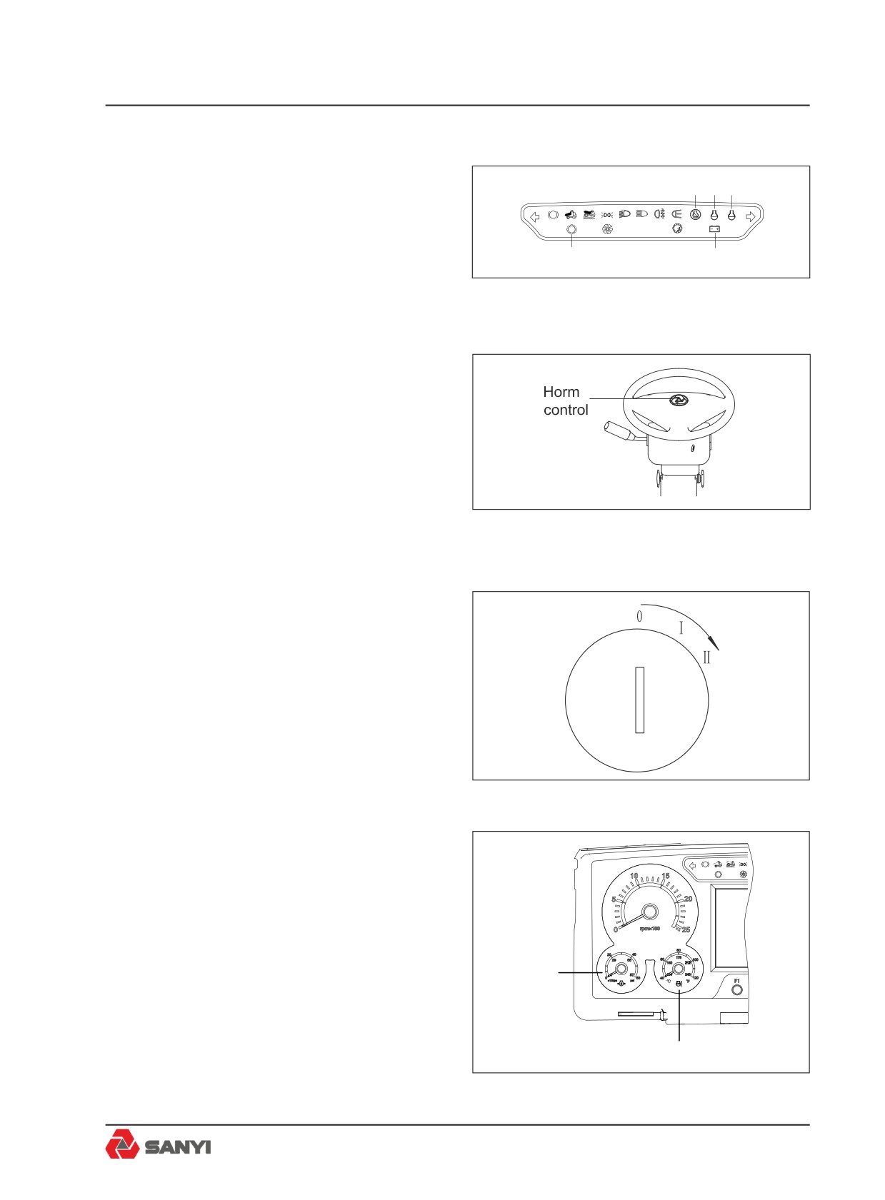
5. Check the instrument panel; the engine
“maintenance”, “warning”, and “stop” indicators
1
2
3
shall flash for several seconds and then
P
!
extinguish; the “Alternator Charging” and
!
“transmission fault” indicators shall be
4
5
constantly on; the Power View display
instrument does not indicate warning (see
Fig 4.16
Fig4-16).
6. Press horn control to sound horn. (see Fig.
4-17).
Caution:Always sound horn before starting
engine or operating anycontrol.
Fig. 4-17
7. Turn key further clockwise against spring
pressure to position 'II' to crank the engine.
Release the key as soon asthe engine starts
firing.
Caution: Never crank the engine more than
30 seconds continuously. Allowstarter(s) at
least 2 minutes cooling time between cranking
periods to avoid overheating. (see Fig.4-18).
Fig. 4-18
8.Check the engine oil pressure gauge. Within
10 to 15 seconds at engine idle,the gauge
P
needle should rise into the yellow zone. If the
!
needle does not rise within 15 seconds, shut
off the engine and do not operate until the fault
is identified and corrected. (see Fig 4-19).
9. Observe the engine water temperature
Engine pressure
gauge. After a few minutes running time at
gauge
moderate load and varying speed, the gauge
needle should be in the green zone. If the
needle moves into the red zone, the engine
Engine water temperature gauge
is over heated and should be shut down
Fig 4.19
immediately.(see Fig 4-19).
4-9
Operating the Truck
4.5 Starting the Engine with
Jumper Cables
Caution: Be sure machines are not touching
each other. Use cables that are equal to cable
size on the machine, for example (1/0) or (2/0).
If jumper cables are used to start an engine,
be sure to follow this procedure:
Connect one end of a jumper cable, usually
coloured red, to the discharged battery
'POSITIVE' (+) post. Connect the other end of
the same cable to the 'POSITIVE' (+) post on
the booster or charged battery.
Connect one end of the second cable, usually
coloured black, to the 'NEGATIVE' (-) post of
the booster battery. Connect the other end of
the 'NEGATIVE' (-) cable to machine frame for
grounding so that if a spark occurs, it is away
from battery fumes (explosive hydrogen).
Check for cause of failure on the dead battery.
WARNING
Hazardous hydrogen gas and
sulphuric acid. Check for required
voltage and polarity connections
to discharged batteries. Excessive
booster voltage and/or incorrect
jumper cable connections, open flame,
lighted cigar, or other ignition source
can cause battery explosion/fire. Keep
all sources of ignition away from
batteries. Do not lean over batteries,
and wear eye protection at all times to
prevent personal injury.
Do not jump start a vehicle by using
arc welding equipment. Currents and
voltages are dangerously high and
cannot be sufficiently reduced to make
the method safe.
4-10
Operating the Truck
4.6 Check Before Driving
Make sure all cab glass, mirrors and lights
are clean. Test all controls to ensure they
are functioning properly. Select 'REVERSE'
momentarily on the transmission shift selector
1/2 oil level
to make sure the reverse alarm sounds.
1/3 oil level
1. Transmission - Hot Oil Level - The parking
brake must be applied and the road wheels
securely blocked while carrying out this
check. With the engine idling, transmission
Fig. 4-20
in 'NEUTRAL' and at normal operating
temperature, the top of the oil column should
be visible in the sight gauge. Add oil if low. If
the top of the column is above the sight gauge,
the transmission is overfull and oil should be
drained.
2. Body and Rear Brake Cooling Hydraulic
Tank - Hot Oil Level - Operate the body hoist
cylinders to their fully-extended positions to
charge all cylinders and lines then lower the
body. With the engine running, and body fully
lowered, the oil level should show in the top
sight gauge. Add oil if low. Under all conditions
the bottom sight gauge should show full.
3. Steering and Braking Hydraulic Tank -
Hot Oil Level - With the engine running, oil
at operating temperature and accumulators
charged, oil must be between the top and
middle sight gauges. Shut down the engine
and operate the steering left and right to
discharge steering accumulator. Operate
treadle valve continuously to discharge
braking accumulators. Oil should show in the
top sight gauge.
4-11