Sany SRT55D Off-Highway Truck. Safety, Operation and Maintenance Manual (2014) - page 3
Safety
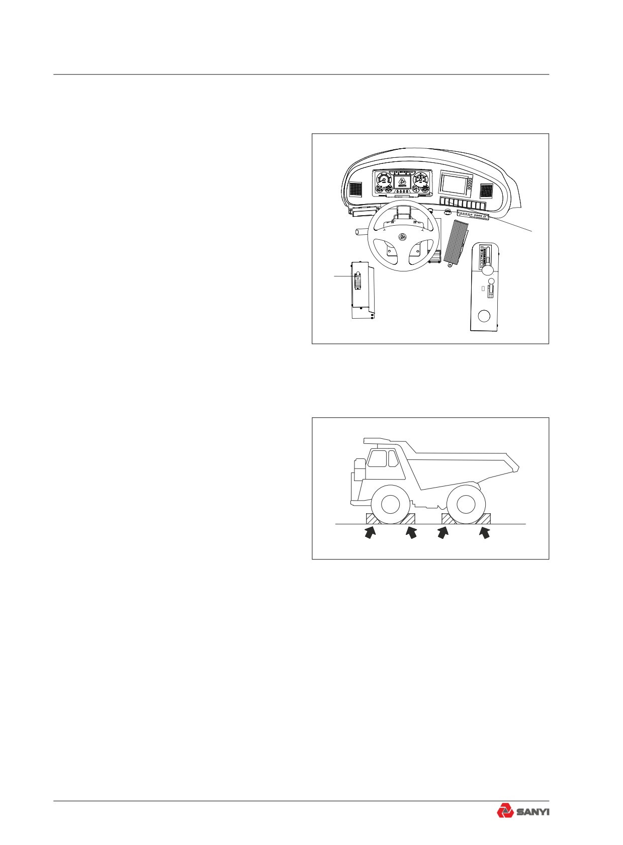
2.4.5 Stop engine before carrying out
maintenance
● Park the machine on solid and flat ground.
● Lower the bucket to the ground.
!
!
● Lower the dump body, set dump control
lever (1) to the HOLD position, lock the
dump control lever , then stop the engine.
2
1
Fig. 2.4-5
● Set parking brake switch (2) to the
PARKING position and put blocks under
the tires to prevent the machine from
moving.
Fig. 2.4-6
2-40
Safety
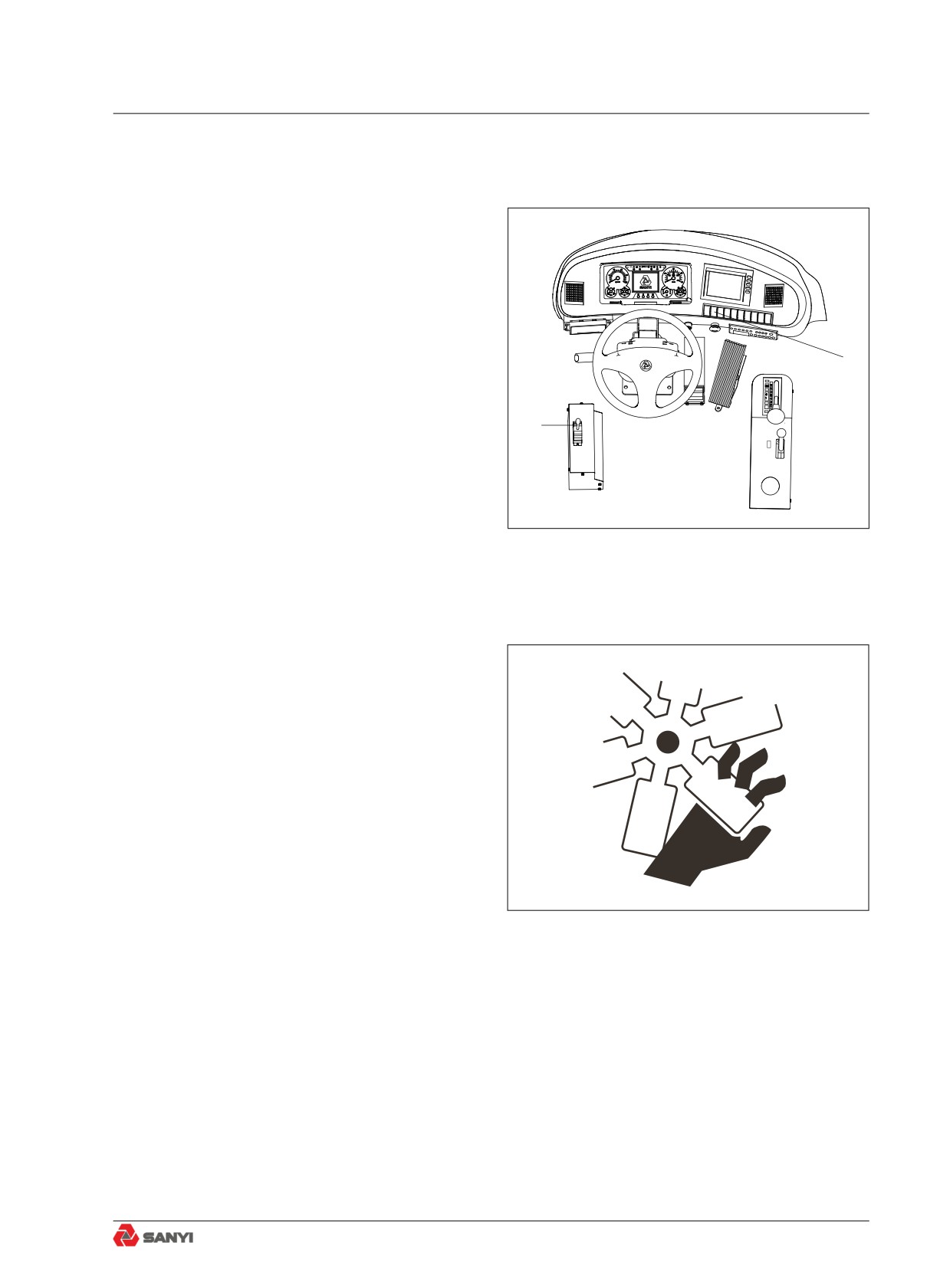
2.4.6 Maintenance with engine running
To prevent injury, no maintenance shall
be carried out when the engine is running.
However, if maintenance has to be done on
!
!
a running engine, at least two worker are
needed to carry out the maintenance.
● One of the workers shall stay in the
operator seat ready to shut down the
2
engine at any time. All the workers
involved shall keep in touch.
● set dump control lever (1) to the HOLD
1
position,then set parking brake switch (2)
to the PARKING position.
Fig. 2.4-7
Fig. 2.4-8
2-41
Safety
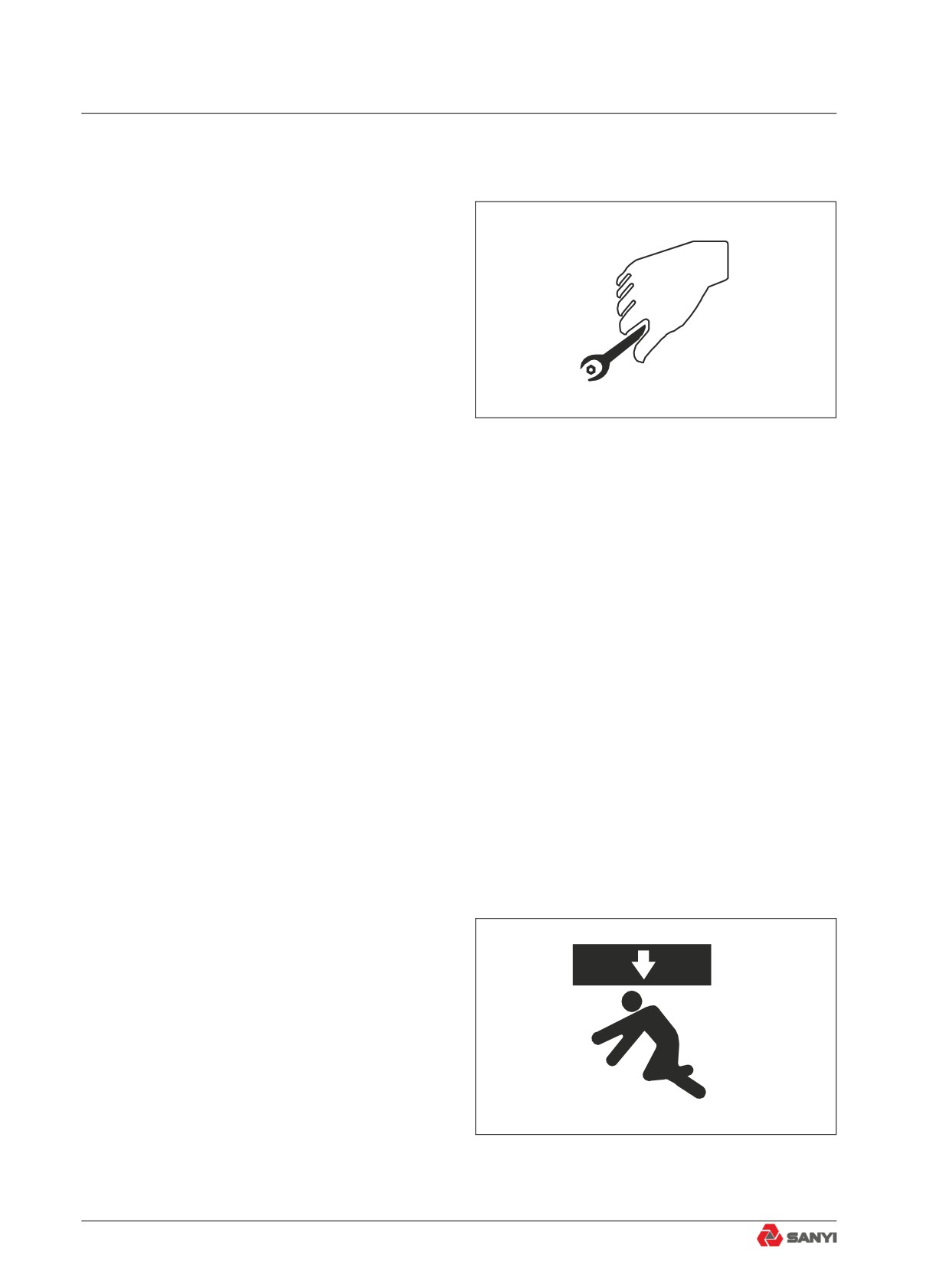
2.4.7 Using proper tools
Use proper tools and use them correctly.
Using damaged, inferior, defective, temporary
tools or using the tools incorrectly could lead
to serious accidents.
Fig. 2.4-9
2.4.8 Handling suspension cylinder
The suspension cylinder and accumulator
are charged with high-pressure nitrogen gas.
If any mistake is made in handling, there is
danger that it may cause an explosion or
serious personal injury.
● Do not remove or disassemble unless
necessary.
● Do not bring it near flame or dispose of it
in fire.
● Do no make holes in it weld it, or use a
cutting torch.
● Do not bear any shock by hammering,
rolling or similar activity.
● Ask your Sany distributor when sealing
gas into the cylinder or replacing gas from
it.
2.4.9 Working under the machine
● If the machine or work equipment has
to be lifted for maintenance, blocks
or supports that are strong enough to
support the machine or work equipment
should be used.
● When carrying out inspection with the
dump body raised, always set the dump
control lever to the HOLD position, then
Fig. 2.4-10
insert the body pivot pin.
2-42
Safety
2.4.10 Work in loud noise
● Wearing ear covers or ear plugs if you
have to work in loud noise for a long time.
● Loud noise may impair your hearing
permanent or temporary.
2.4.11 Use compressed air
● When compressed air is used for
cleaning, flying particles may cause
personal injury. In this case, wear
goggles, dust-preventive mask, gloves
and other protective gear.
2.4.12 Use a hammer
● When using a hammer to strike hard
metal parts such as pin, bucket teeth,
cutting edge or shaft, the flying of parts
and metal pieces may cause bodily injury.
Therefore, wear goggles and gloves and
ensure the surrounding area is clear of
any other people.
Fig. 2.4-11
2.4.13 Welding operation
● Welding operation may lead to fire or
electrocution.Only qualified welders are
allowed to conduct welding operation
using proper equipment.
2-43
Safety
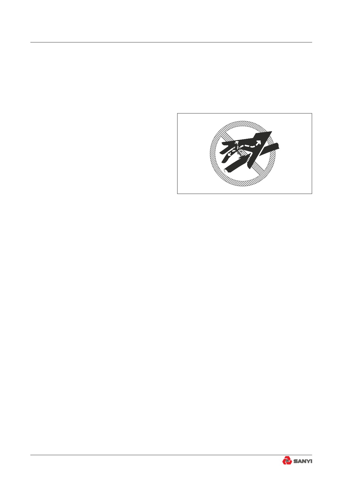
2.4.14 Precautions with high-pressure
oil
The hydraulic system is always under
pressure.Make sure pressure in hydraulic
circuits has been relieved before checking or
replacing the lines. Residual pressure in the
circuit may cause serious accidents.
Release system pressure before
maintainingthe hydraulic system:
1) Remove thebutterfly nut of the vent
valve and pressthe venting button to release
the internalpressure of the hydraulic tank;
2) Shut down engine.Rotate steering
wheel to the two directions for several turns
and release steering system pressure. Press
foot valve continuously to release pressure of
Fig. 2.4-12
brake accumulator.
●
Open fire is not allowed around the
hydraulic system. Remove splashed
hydraulic oil as quickly as possible.
●
Diesel oil or pressurized hydraulic oil can
penetrate skin or eyes, causing serious
injury, blindness or death. It is hard to find
the leaking of hydraulic oil with naked
eyes.A cardboard or wooden board is
necessary for checking for leaks. Never
touch leaking liquid with bare hand. Wear
face shield or safety goggles to protect
your eyes. If any liquid penetrates your
skin, flush with clean water immediately
and get medical attention as soon as
possible.
●
The fuel lines are under high pressure
when the engine is running. When
checking or servicing the fuel system,
shut down the engine and wait for 30
seconds till internal pressure drops before
operation.
2-44
Safety
2.4.15 High-pressure hoses
If oil leaks from high-pressure hose, fault or
even fire may occur. If any bolt on hose is
loose, stop operation and tighten it to specified
torque. In case of hose damage, stop
operation immediately and contact Sany HM
authorized dealer.
Replace the hose immediately in case of the
following problems:
● Damage or leak of hydraulic hose fitting.
● Damage or break of outer cover, or
exposed steel wires of reinforcement
layer.
● Ballooning outer cover in some places.
● Distortion or crushing of movable parts.
● Impurities in outer cover.
2.4.16 Hot cooling system
● When engine temperature rises, pressure
of the cooling system increases. Before
removing the radiator cover, stop the
engine and let the system cool down. The
radiator cover could only be removed after
the coolant in it has cooled down.
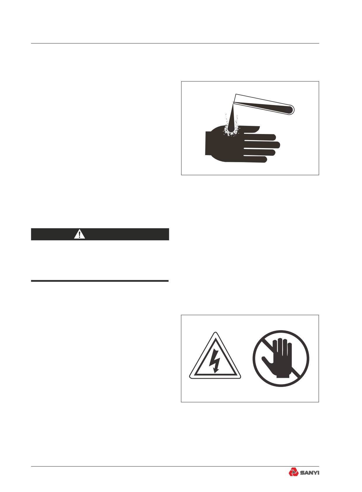
WARNING
Touching hot high-pressure coolant may
cause serious injury.
Fig. 2.4-13
2-45
Safety
2.4.17 Air-conditioning system
Keep fire source away when servicing
airconditioning system.
● In maintenance of air-conditioning
system, observe the instruction on the
refrigerant cylinder and use it correctly.
The type of refrigerant is R134a. Use of
other refrigerants may damage the air-
conditioning system.
● Refrigerant getting into eyes may cause
blindness. It may cause frostbite if
splashed on your skin.
Fig. 2.4-14
● Obey local material disposal regulations.
Never discharge refrigerant directly into
the air.
WARNING
Refrigerant R134 a is a harmless gas
under room temperature. It will change
into highly toxic gas when burning.
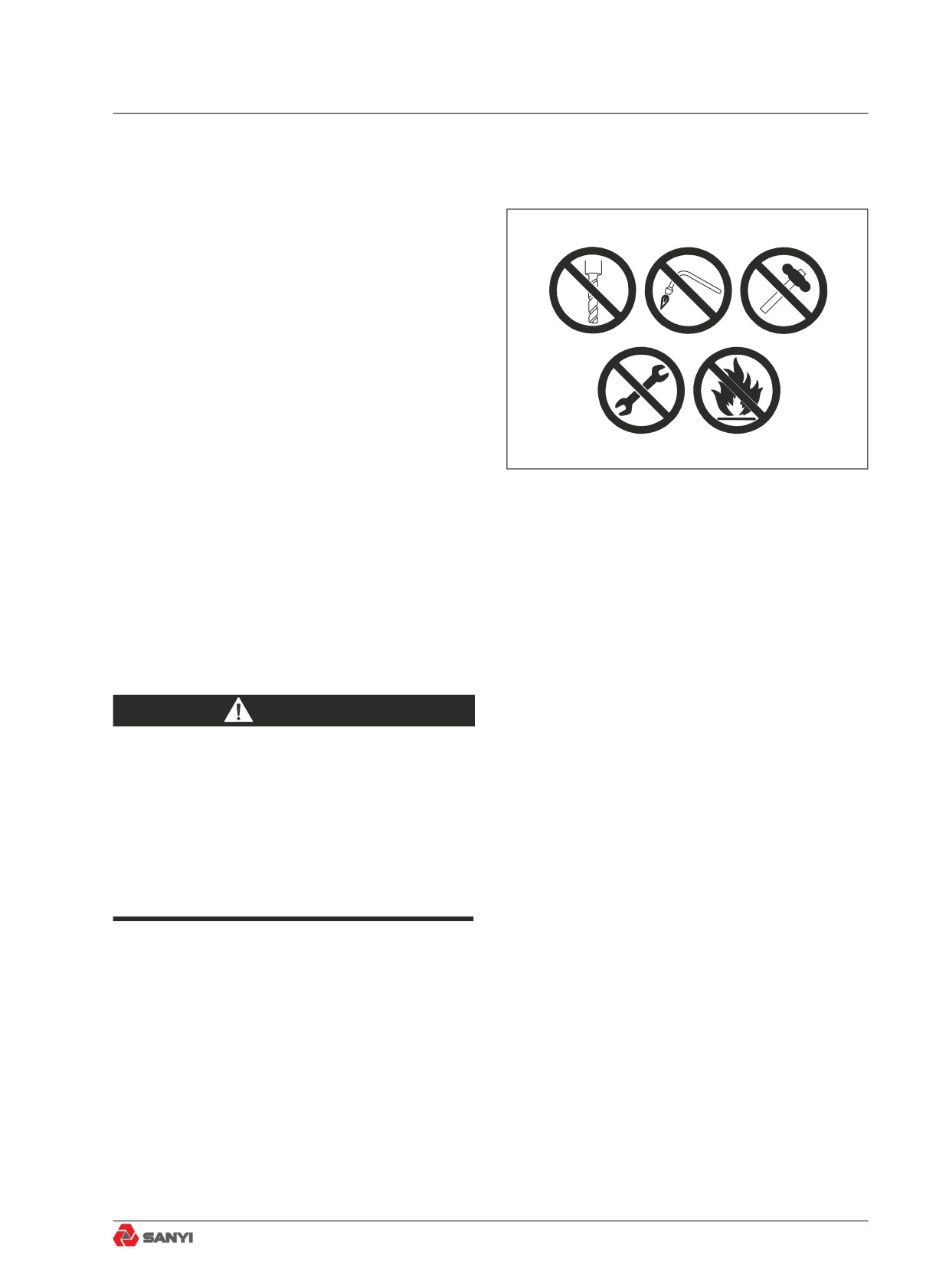
2.4.18 High voltage precautions
● When the engine is running or has just
been shut down, high voltage can occur in
fuel injector terminal and engine controller.
Since there is danger of electrocution,
never touch fuel injector or interior of
engine controller.
● Please contact Sany distributor if you
have to access fuel injector terminal or
interior of engine controller.
Fig. 2.4-15
2-46
Safety
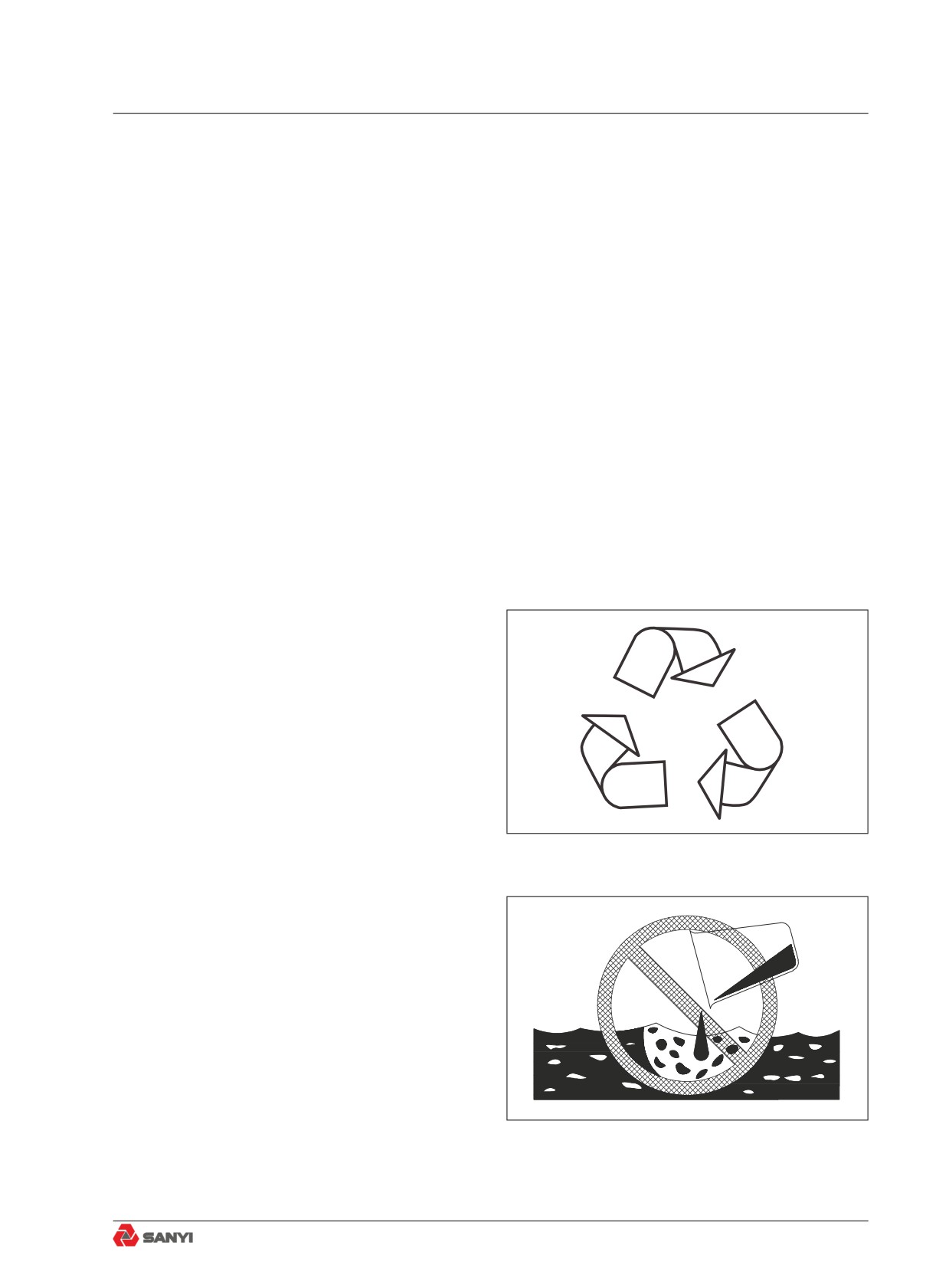
2.4.19 Accumulator
Accumulator contains highly pressurized
nitrogen.Improper operation of accumulator
can cause explosion and serious accidents.
Therefore, the following precautions must be
observed:
● Never disassemble the accumulator.
● Never let the accumulator be near a fire
source or exposed in flame.
● Never punch, weld or flame-cut on
accumulator.
● Never strike or roll the accumulator, or let
Fig. 2.4-16
it bear any impact.
● The gas must be released when disposing
of the accumulator. Contact Sany
distributor for this disposal.
2.4.20 Avoiding fire and explosion
DANGER
Never smoke when handling the fuel or
maintaining the fuel system. The gases in
empty fuel tank can cause explosion easily.
Never carry out flame-cutting or welding
operation on fuel pipe, fuel tank or fuel
vessels, which can lead to fire, explosion,
injury or death.
● Then engine must be shut down and
electrical equipment must be switched
off when refueling the tank. Be extremely
careful when adding fuel to a hot engine.
No sparks shall occur around the
grounding nozzle.
● Handle all solvents and dry chemicals in
a place with good ventilation according to
the steps indicated on vessel.
2-47
Safety
● Clean the machine of all dust and
residuals. Never place greasy rag or other
flammable materials on machine.
● When cleaning the parts and components,
use nonflammable solvents instead of
gasoline, diesel oil or other flammable
fluids.
● Store flammable liquids and materials
in suitable vessels as required by safety
laws and regulations.
● Check fire extinguishers, fire-fighting
system and fire detectors (if equipment)
and make sure they are ready for use.
2.4.21 Regular replacement of
safetyrelated parts
Safety-related parts such as hoses and
seat belt must be replaced regularly for the
consideration of operating the machine safely
in a long term.
● Materials of some parts may deteriorate
naturally when exceeding specific
time limit. Repeated use may lead to
deterioration, wear and damage, hence
the accidents and serious injury. Through
merely visual inspection or feel it is hard
to find out how long the parts could
serve. Therefore, regular replacement is
necessary.
● Repair or replace any safety parts once
found defective regardless of its service
time.
2.4.22 Maintenance operation
● Check all parts and replace the worn,
broken and damaged parts during
repairing operation. Over-worn and over-
damaged parts may fail in operation and
cause injury and death. Replace damaged
2-48
Safety
or illegible signs and marks.
● Tighten all fasteners and connectors to
specified torque.
● Install all guards, covers and hoods
after repair and service. Replace or
repair damaged guards. Only the type of
hydraulic oil approved or recommended
by Sany should be used to make up the
hydraulic system.
● Start the engine and check for any
leaks (check the hydraulic system), and
operate all control devices to be sure of
their proper functioning. Make road test
if necessary. Shut down the engine and
check the work you have done (see if
there are missing pins, gaskets and nuts).
Check again all hydraulic oil levels before
operation.
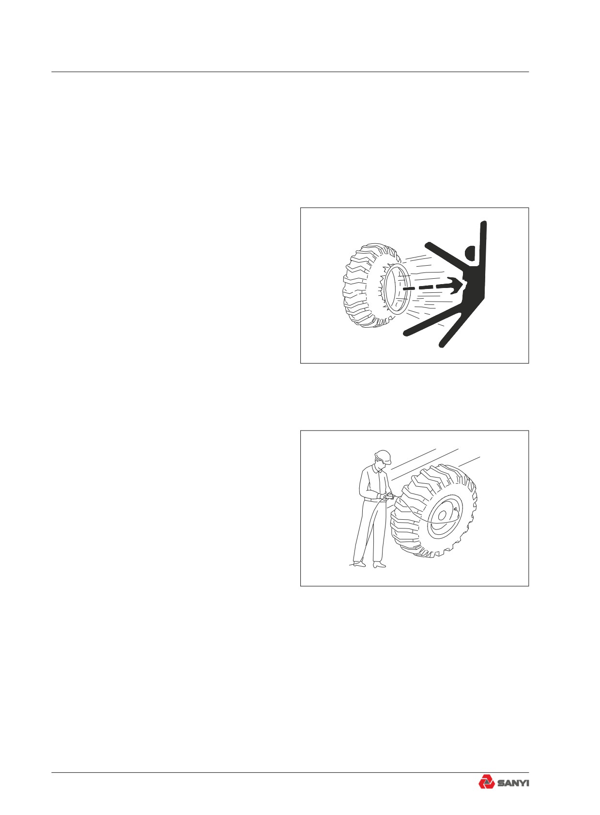
2.4.23 Proper disposal of wastes
Improper disposal of wastes harms
the environment and ecology. Consult local
environmental protection department or Sany
distributors for methods of recycling and waste
disposal.
● Potential harmful substances used in
Sany products include hydraulic oil,
Fig. 2.4-17
fuel, cooling liquid, refrigerant, filter and
batteries etc.
● Use leak-proof vessels to hold discharged
fluids. Never use food or beverage
containers.
● Never dump waste fluids directly to the
ground, sewage or water source.
● Leaking of refrigerant from air conditioner
can spoil the atmosphere of the globe.
Related laws and regulations must be
followed to recover or regenerate the
refrigerant.
Fig. 2.4-18
2-49
Safety
2.5 Precautions With Tires
2.5.1 Handling tires
Explosive separation of a tire and/or rim parts
can cause serious injury or death.To ensure
safety, always do as follows.
●
When carrying out maintenance,
disassembly, repair, or assembly of the
tire or rim, special tools and procedures
must be used. Always ask your Komatsu
distributor to do the work.
●
Use only specified tires and inflate them
to the specified pressure.
●
When pumping up the tires, check that no
other person is standing near the tire, and
install an air chuck with a clip that can be
secured to the air valve. To prevent the
tire inflation pressure from becoming too
Fig. 2.5-1
high, measure the pressure from time to
time with an air gauge while pumping up
the tire.
●
If the pressure goes down abnormally or
the rim parts go not fit the tire, there is a
problem with the tires or rim parts. Always
contact your Komatsu distributor for
repairs.
●
If the rim parts are not fitted properly
when the tire is being pumped up, there
is danger that the rim parts may fly off, so
set up a protective fence around the tire,
and do not stand directly in front of the
rim. Stand beside the tread when pumping
Fig. 2.5-2
up the
●
Do not adjust the tire inflation pressure
immediately after traveling at high speed
or carrying out operations under heavy
load.
●
Never carry out welding or light a fire near
the tire.
●
Always release all pressure from a single
tire, or from both tires of a dual assembly,
prior to removing any rim components.
2-50
Safety
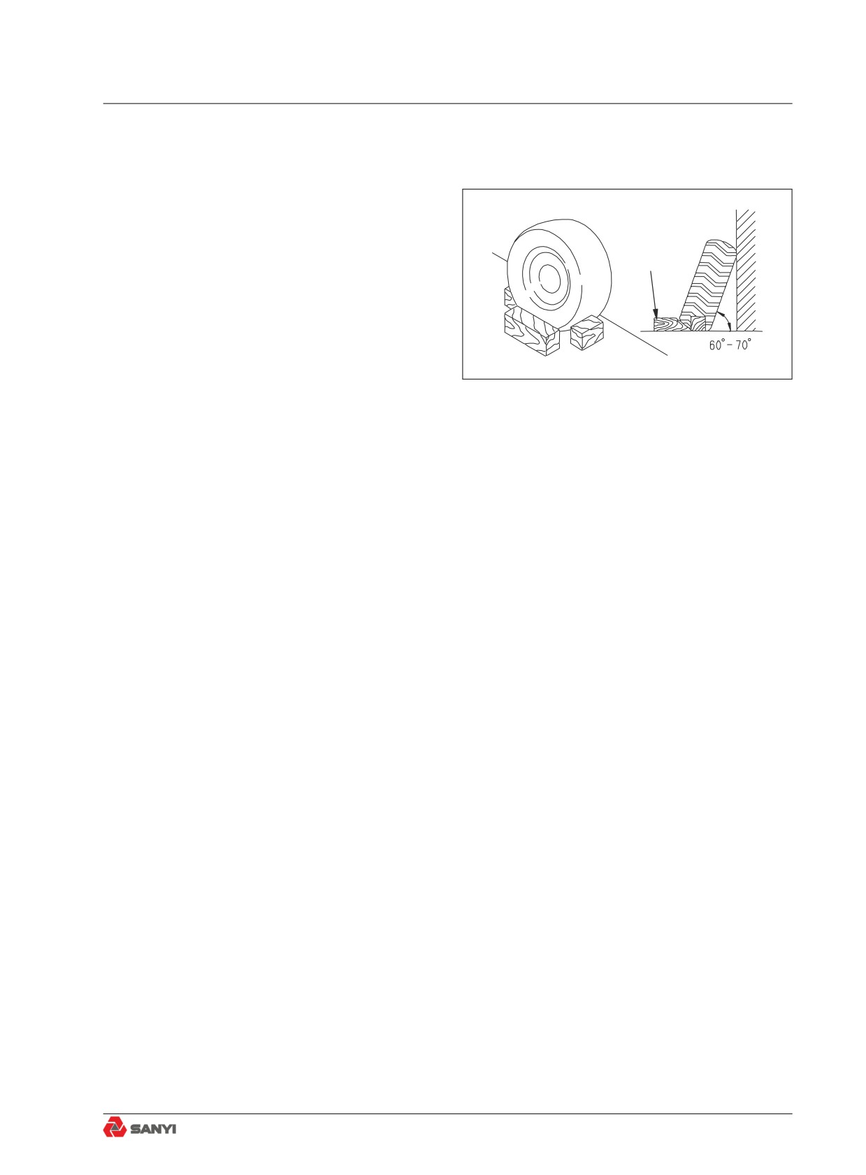
2.5.2 Precautions when storing tire
● Store the tires in a warehouse where
unauthorized persons cannot enter.
Always erect a fence and put up "No
Entry" signs if the tires must be stored
Block
outside. Stand the tire on level ground,
and block it securely so that it cannot roll
or fall over if any person should touch it.
● Do not lay the tire on its side. This will
deform the tire and cause it to deteriorate.
● If the tire should fall over, do not attempt
Fig. 2.5-3
to stop it. Get out of the way quickly.
2-51
Controls and Operating
3 CONTROLS AND OPERATING
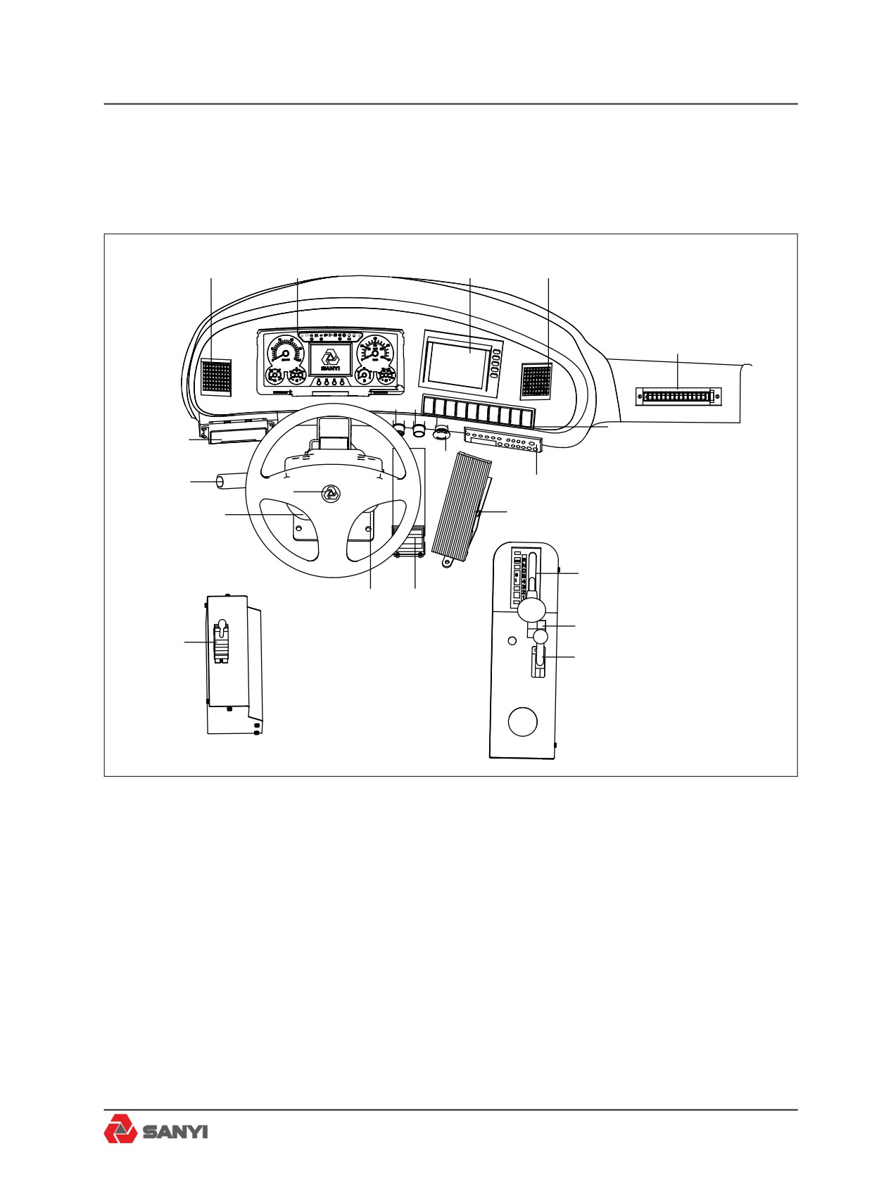
3.1 Controls and Instruments
1
2
3
4
P !
!
5
10
9
6
20
8
19
7
18
11
17
12
16
15
13
21
14
Fig 3-1
1. Air Outlet
11.Transmission Gear Shift Selector
2.Combination instrument
12.Retarder Control
3. Reversing Monitor
13. Hydraulic Retarder Lever
4. Air Outlet
14. Service brake pedal
5. Air Outlet
15. Ignition and Starter Key Switch
6. Switch
16. Steering Wheel
7. Radio / MP3
17. Horm control
8. Emergency brake button
18. Headlight Dipper, Direction Indicator, Wind-
screen Wiper/Washer
9. Cigar lighter
19. Air Conditioner Control
10. Accelerator Control
20. Body Control Lever
3-1
Controls and Operating
1
2
3
4
5
6
7
8
9 10 11
12 13
P
!
!
17
16
15
14
P
!
!
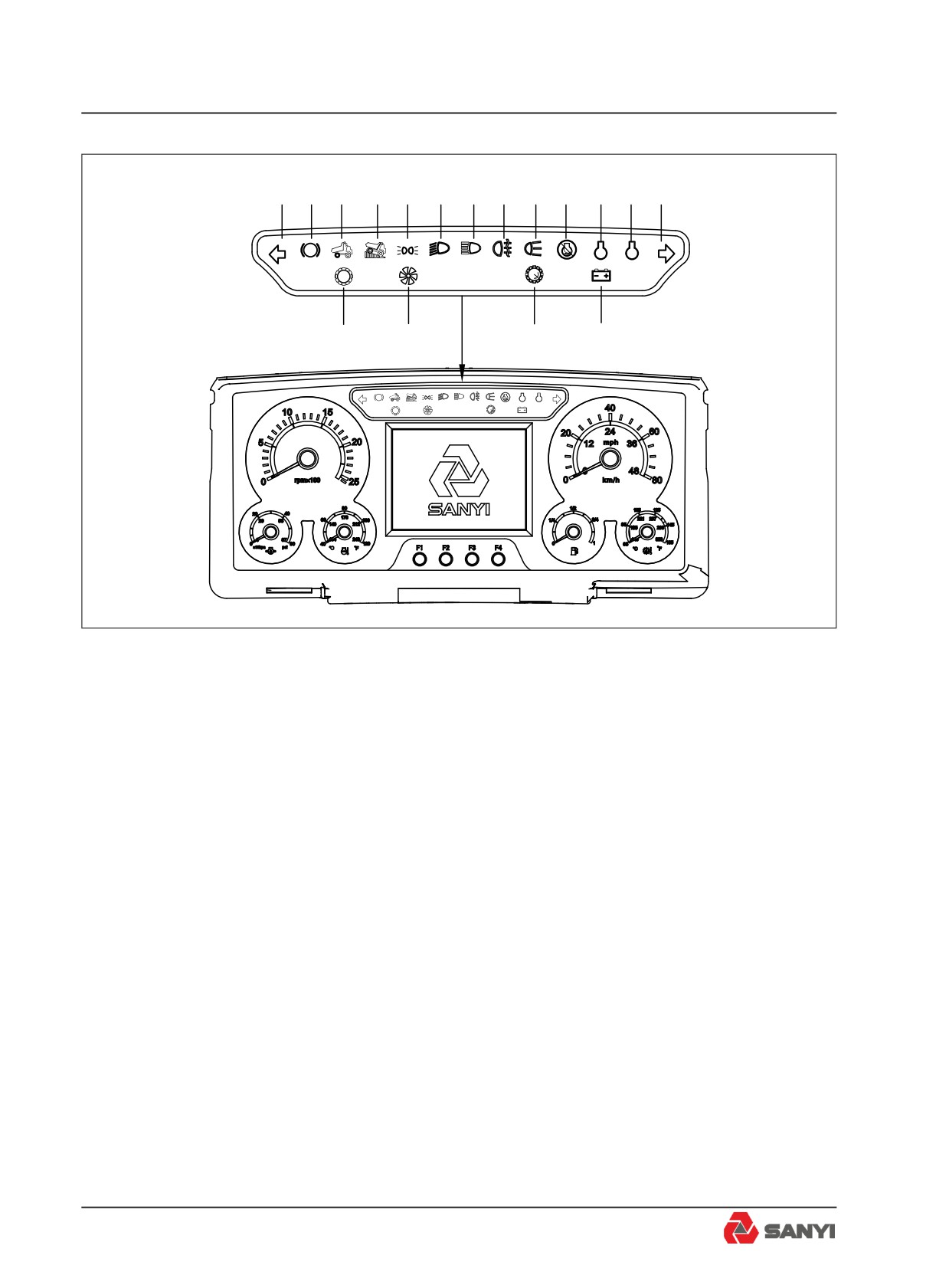
Fig 3-2
3.2 Indicator
1. Left steering Indicator (Green) - Flashes
when the left indicator lights are operating.
2. Parking Brake (Red)-Illuminates when the
parking brake is applied.
3. Body up (Yellow) - Illuminates to indicate
that the body is NOT resting on the chassis.
Never move the machine until this light goes
OUT.
4. Retarder Indicator (Yellow) - Illuminates
when the retarder is applied.
5. Side marker lamp (Yellow) - Such lamp will
be on when side marker lamp starts to work.
6. Dipped beam Indicator (Green)-Illuminates
when dipped beam head lamps start to work.
7 High beam Indicator (Blue)-Illuminates when
high beam head lamps start to work.
8. Fog Indicator (Yellow) - Such lamp will be
on when fog lamps start to work.
9.Rear Indicator (white)
10. Engine Stop Indicator Red) - When the
'Stop' light comes on, the computer has
3-2
Controls and Operating
detected a major malfunction in the engine
that requires immediate attention.
Stop the machine when this light illuminates
and do not operate until the fault is corrected.
11. Engine Maintenance Indicator ( White)
- Indicates that the engine needs to be
maintained. See Cummins Manual for details
about specific maintenance items.
12. Engine Warning Indicator (Yellow) - When
the 'Warning' light comes on, the computer has
detected a fault in the engine which may result
in a power loss. The fault should be diagnosed
and corrected at the earliest opportunity.
13. Right steering Indicator(Green) - Flashes
when the right indicator lights are operating.
14. Alternator Charging (Red) - Illuminates to
indicate when the alternator is not charging.
15. Transmission Over speed Indicator (red)
- Illuminates when the transmission ECU
senses transmission speed above 2350 rev/
min.
16. In-converter Indicator (Green)- Illuminates
when the transmission is in Torque Converter
drive. It goes OUT when Lockup is engaged.
17. Check Trans Indicator (Red) - Illuminates
to alert of a fault in the transmission shift
system or abnormal transmission temperature.
The light will illuminate when the ignition key
switch is turned to position '1' to provide a bulb
and system check and should go off a few
seconds after the engine is started.
3-3
Controls and Operating
1
2
P
!
!
7
6
5
4
3
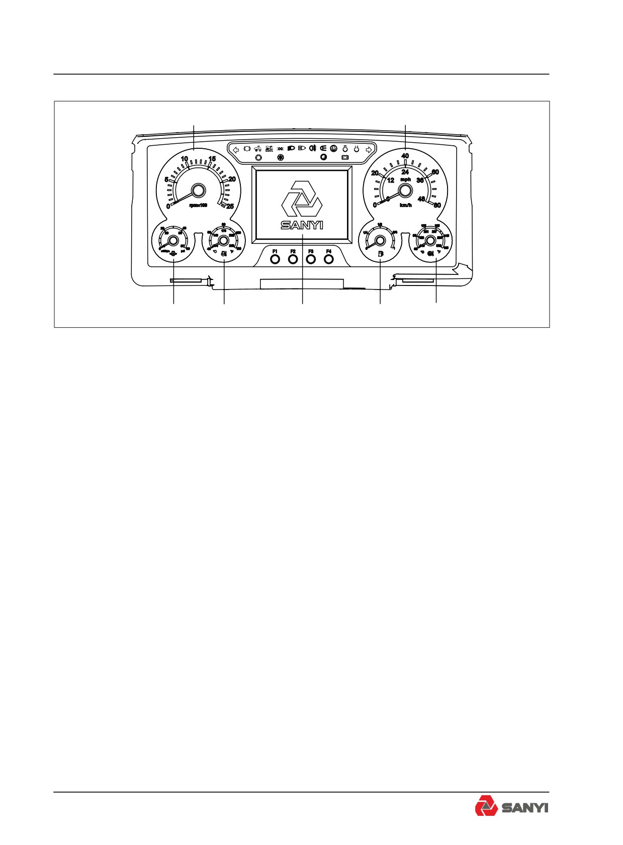
Fig 3-3
3.3 Instruments
1. Tachometer
Driven by CAN bus; it indicates engine speed
in revolutions per minute. When the pointer
is located in white area said speed is normal,
and once the pointer is located in red area
that speed is too high, should reduce speed
immediately.
2. Speedometer
Driven by CAN bus; it indicates vehicle
running speed. When the pointer is located in
white area said speed is normal, and once the
pointer is located in red area that speed is too
high, should reduce speed immediately.
3. Transmission Oil Temperature Gauge
The pointer indicates transmission oil
temperature value. Such meter is directly
connected to transmission temperature
sensor. When the pointer is located in white
area said transmission oil temperature is
normal, and once the pointer is located in red
area that transmission oil temperature is too
high, movement, the buzzer for 10 seconds,
then shut down automatically. In the electric
power the same fault buzzer action only once.
3-4
Controls and Operating
4. Fuel level gauge
The pointer indicates percent of full tank
a actual fuel level. Such meter is directly
connected to fuel level sensor. When the
pointer is located in white area said fuel level
is normal, and once the pointer is located in
red area that fuel level is too low, movement,
the buzzer for 10 seconds, then shut down
automatically. In the electric power the same
fault buzzer action only once.
SANY MINING EQUIPMENT
5. Display
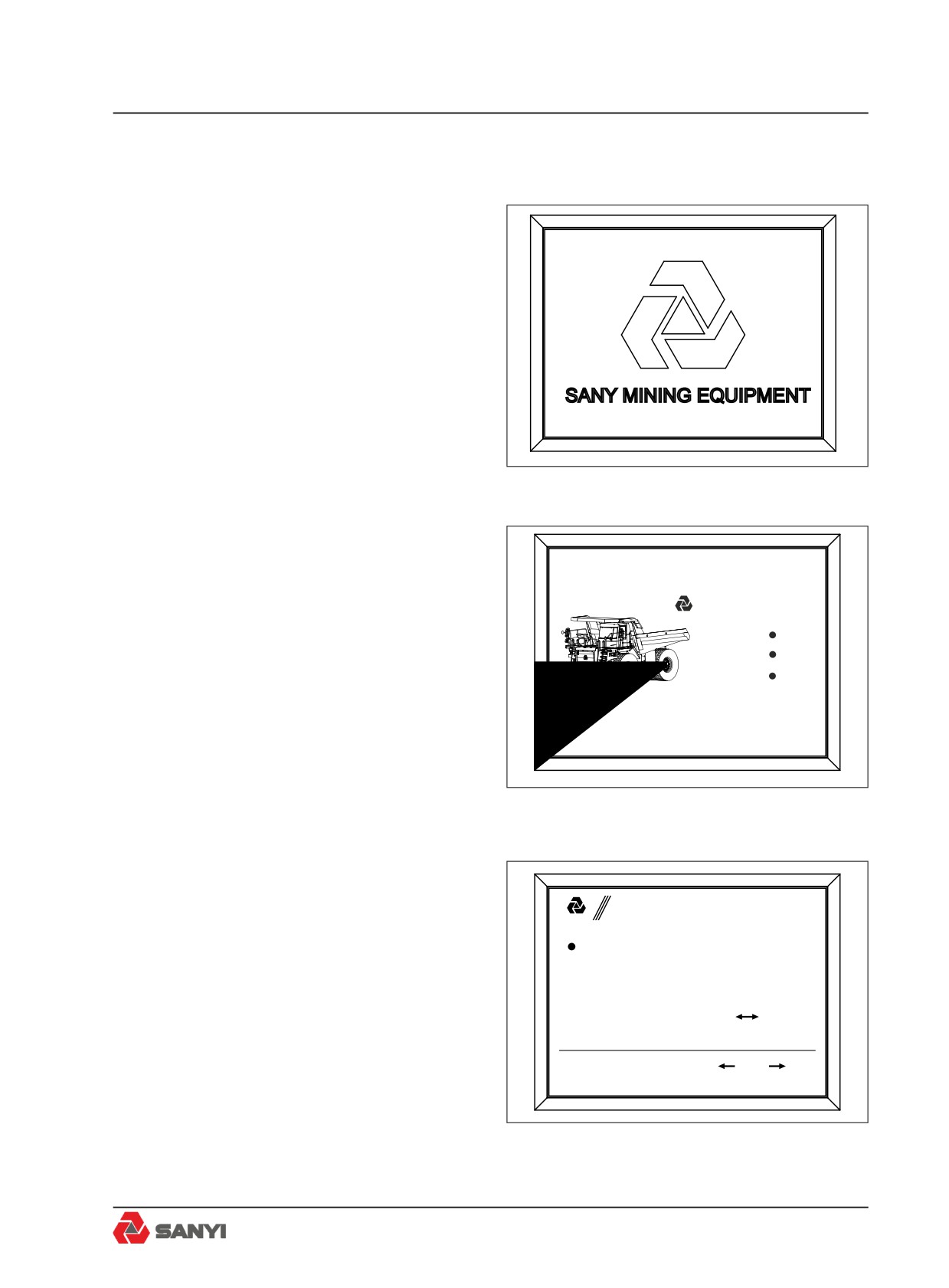
1. Turn on power supply, start the key switch
toΙ, the display shows "sany " boot screen(see
fig3-3.1), and all of the signal indicators are
Fig 3-3.1
applied, 3 seconds after the display shows
work interface, the lights go out at the same
time.
08-25-2012
15:10:25
Wed
SANY Mining Equipment
Engine
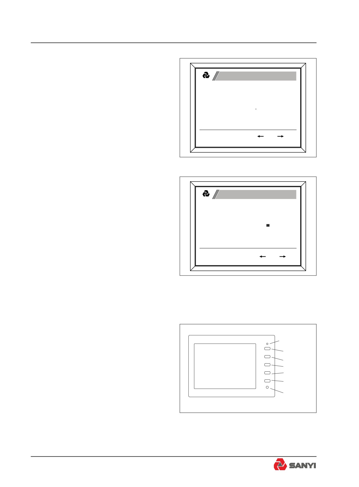
2. Click F2 key to change from work interface
Transmission
to system function interface, and the work
Monitor
interface is default(see fig3-3.2).
VEH DIST
ENG HRS
XXXXXX
km
XXXXX.Xh
Fig 3-3.2
3. Enter the system function interface, F1 key
to return, F2 key for confirmation key, the F3
key to move up, and F4 for down key(see fig3-
3.3).
System Function
SANYI
Engine information
Parameters query
4. Under the system function interface, click
Parameters setting
Monitoring system
the F3 key or F4 key to choose the function
Restore password
Controller I/O
Backlight adjust
and click F2 key to confirm.
System time setting
Buzzer time setting
Chinese
English
Take the case of setting system time to
demonstrate operation method:
F1:ESC F2:Enter F3:
F4:
Under the system function interface:
a. click F3 key or F4 key to choose the number
of the time;
Fig 3-3.3
3-5
Controls and Operating
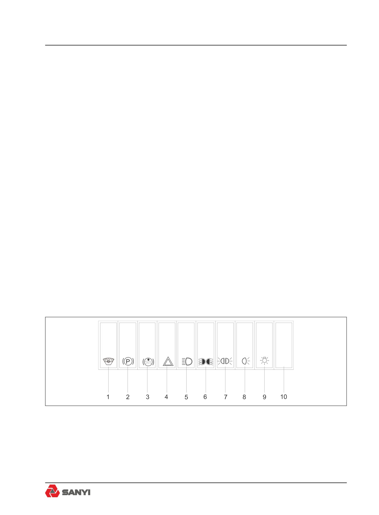
b. click F2 key to confirm, then the cursor will
automatically move to the next number(see
System Time Setting
fig3-3.4);
SANYI
c. When the cursor to the last digit (the second
single digits) , click F2 key to confirm the
2012Y08M13D
current changes, and then click F2 key again
12H30M25S
to end the modify Settings until appear a
square green claim(see fig3-3.5),
d. Click F1 key to return to the system function
F1: ESC F2: Enter F 3:
F4:
interface.
6. Engine Water Temperature Gauge
Driven by CAN bus; it indicates engine coolant
Fig 3-3.4
temperature value. When the pointer is located
in white area said engine coolant temperature
is normal, and once the pointer is located in
System Time Setting
red area that engine coolant temperature is too
SANYI
high, movement, the buzzer for 10 seconds,
then shut down automatically. In the electric
2012Y08M13D
power the same fault buzzer action only once.
12H30M25S
7. Engine Oil Pressure Gauge
Driven by CAN bus; it indicates engine oil
pressure value. When the pointer is located in
F1: ESC F2: Enter F 3:
F4:
white area said engine oil pressure is normal,
and once the pointer is located in red area that
engine oil pressure is too high, movement,
Fig 3-3.5
the buzzer for 10 seconds, then shut down
automatically. In the electric power the same
fault buzzer action only once.
3.4 Reversing Monitoring System
Power Supply
Indicator
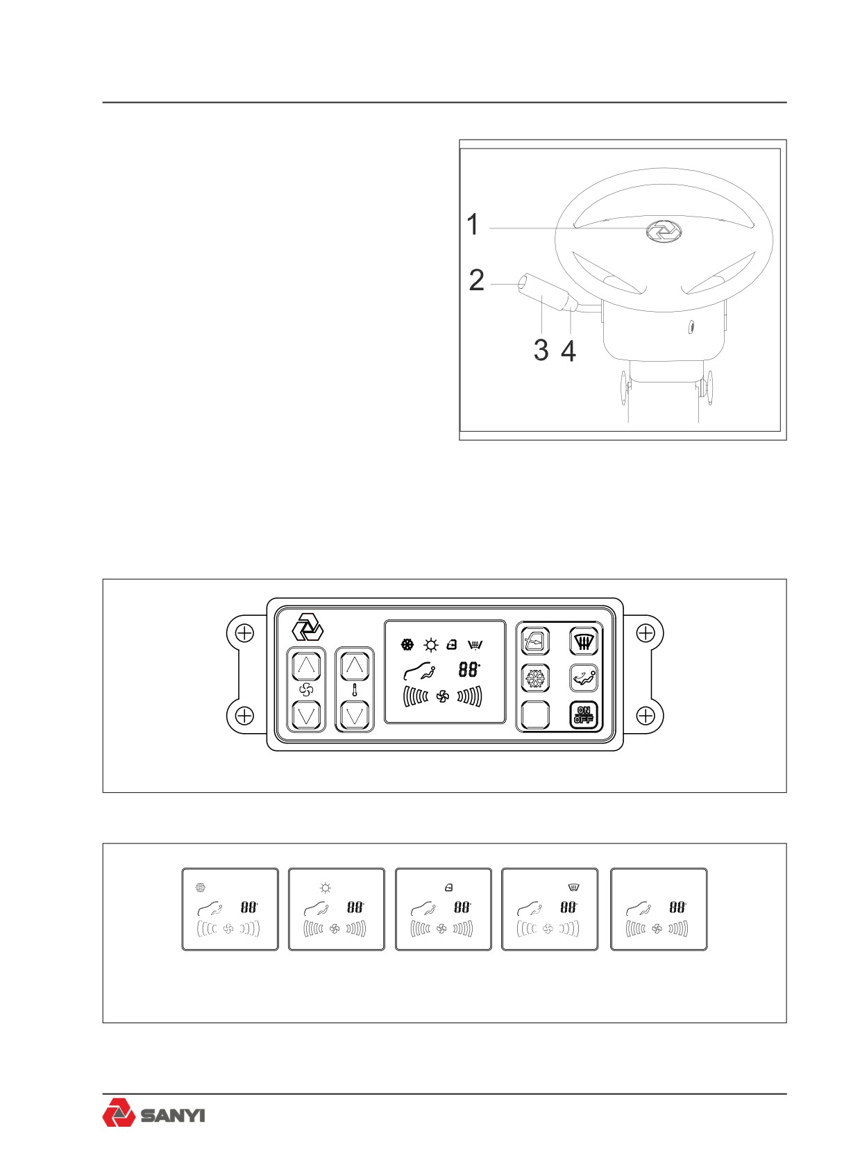
The monitor (see Fig 3-4) on instrument panel
Power
is mainly used for monitoring the reversing
Supply
truck as well as watching the situation behind
Menu
č+Ď
truck. The matching camera is at the rear part
č-Ď
of truck.
Mirror
Operation instructions:
/Normal
Light
1.Power Supply Switch
Sensor
There are two methods available for turning
on the monitor: The monitor will be turned on
Fig 3-4
automatically when the transmission gear shift
selector is placed at REVERSE position; press
down the power supply key on monitor to turn
3-6
Controls and Operating
on the monitor, and press again to turn off the
monitor.
The Power Supply Indicator (Red) will be on
when the monitor is turned on and it will be off
when the monitor is turned off.
2.Contrast Control
Press the MENU key until Contrast appears
on the screen, then press “+” or “-” key to
increase or decrease image contrast.
3.Brightness Control
Press the MENU key until Brightness appears
on the screen, then press “+” or “-” key to
increase or decrease image brightness.
4.Volume Control
Press the MENU key until Volume appears
on the screen, then press “+” or “-” key to
increase or decrease volume.
5.Mirror/ Normal Selection
Press such button to set reversal effect of
image.
Reversal image can be displayed when switch
is placed at MIR position.
Normal image can be displayed when switch
is placed at the NOR position.
3.5 Switches
Fig 3-5
1. Economical/Powerful Mode Switch
Allows the operator to select between the
transmission 'POWER' and 'ECONOMY' shift
schedules.
3-7
Controls and Operating
Caution: Move the transmission shift lever
to Neutral befor selecting schedule.
2. Parking Brake Switch
The driver can perform rear braking
independently. Such brake can be used for
load parking or stopping.
3. Front Brake Pressure Reduction
Press bottom of switch to give a
50% reduction in front brake pressure. The
lower front pressure reduces the risk of wheel
lockup in slippery conditions. To return to full
front brake pressure; press the top of the
switch.
4. Hazard Warning Lights
Press bottom of switch to make four Diretion
Indicators flash simultaneous; press the top of
the switch to turn them off .
5. Headlight
Press the bottom of the switch to electrify the
Headlight (Dipped Beam/Main Beam); the
Dipped Beam/Main Beam of the combined
switch will be effective; otherwise, they will be
ineffective.
6. Fog Lamp Switch
Press switch bottom to turn on the rear fog
lamp. Press the upper part of switch to turn off
the rear fog lamp.
7. Clearance Lamp Switch
Press switch bottom to turn on the front and
rear clearance lamp. Press down the upper
part of switch to turn off the lamp.
8.Rear lamp switch
Press switch bottom to turn on rear lamp,
Press down the upper part of switch to turn off
rear lamp.
9. Small Lamp Switch
Press switch bottom to turn on rocker switch
indicator. Press down the upper part of switch
to turn off indicator.
10.Backup Switch
3-8
Controls and Operating
3.6 Combined Switch
1. Horn
Button pushed in = Horn Sounds.
2. Washer
Ring Pushed = Windscreen wash
3. Windscreen Wiper
Position J = Not used
Position 0 = Stop, reset wiper
Position I = Wiper Slow Speed
Position Ⅱ = Wiper Fast Speed
4. Headlight Dipper and Flasher
Control downwards = Main Beam
Neutral Position = Dipped Beam
Control Upwards = Headlight Flash
Fig 3-6
3.7 Air Conditioner Control Panel
3.7.1 Air conditioner control panel
设置
C
图 3-7
Set up
C
Set up
C
Set up
C
Set up
C
Set up
C
Refrigeration mode
ḤHeat mode
Circulating mode
Defrosting mode
Blower mode
Panel display picture
3-9
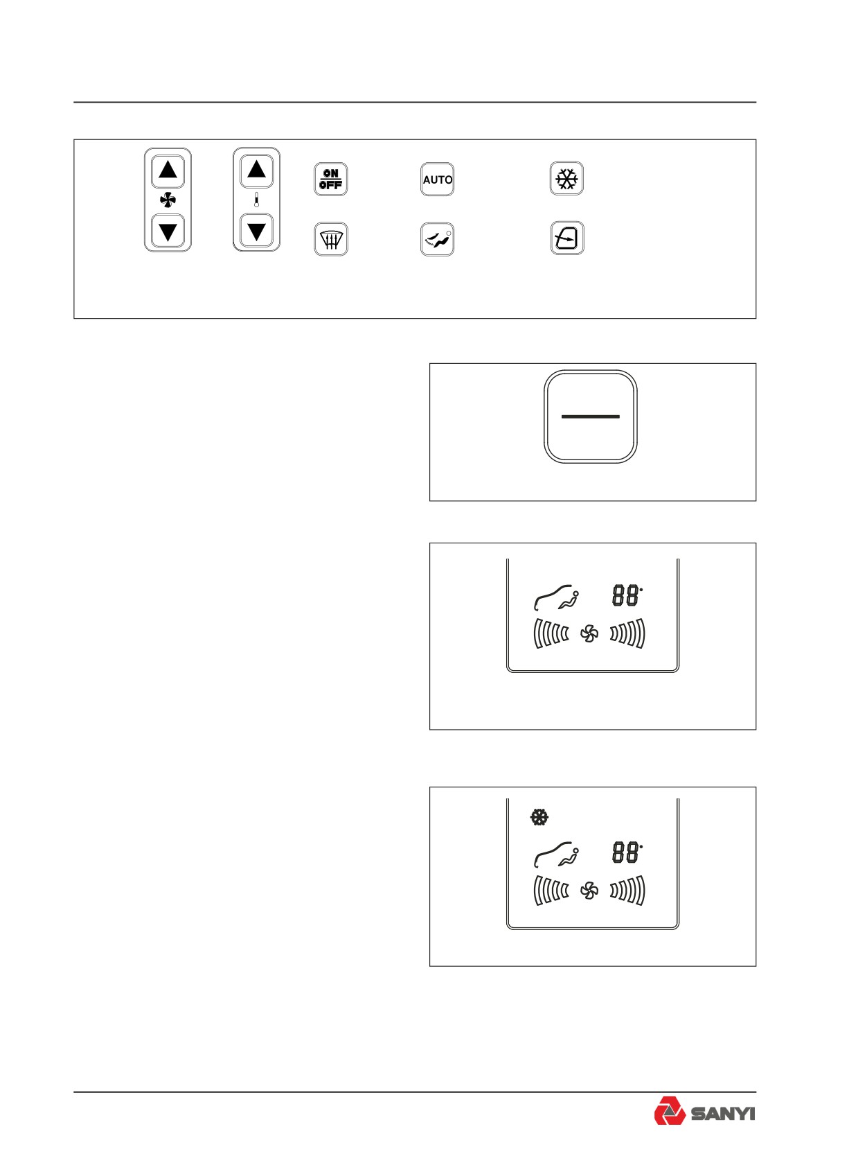
ON/OFF
Refrigeration/ Heat
Auto/ Manual
key-press
key-press
key-press
Defrosting
Air circulating
Blower mode
key-press
key-press
key-press
Wind speed
Temperature adju-
key-press
sting key-press
Panel key-press picture
Operation instructions
a. Open
Press power supply key to turn on the
ON
machine; the controller will automatically
OFF
select the working mode according to the air
conditioning system inside truck; then press
图3-7.1
power supply key to turn off power supply and
all the outputs.
b. Blower mode
Press mode key to set air conditioner working
Ḥ设置
C
mode (automatic, refrigerating, heating,
ventilating).
图3-7.2
c. Refrigeration
Forced refrigerating function:
1. On blower mode, press Refrigeration/ Heat
Ḥഡᇂ
C
key-press, air conditioner is on refrigeration
statues, LO will be displayed to activate forced
refrigerating mode when the temperature is
set smaller than 15°C(larger than 30°C) under
refrigerating mode. On refrigeration statues,
图3-7.3
press wind speed key-press can adjust wind
speed(low,middle and high).
2. On refrigeration statues, wind speed is on
high (wind speed and night mode can adjust
but temperature can not).
3-10
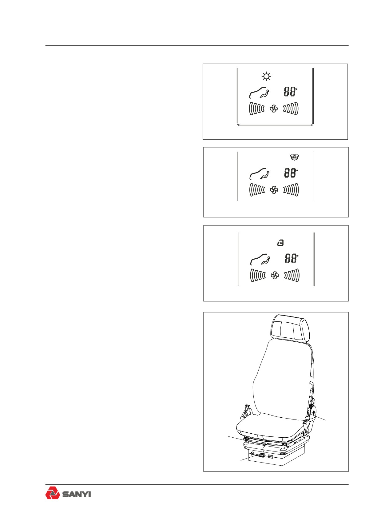
d. Heating mode
Forced heating function: HI will be displayed
to activate forced heating mode when the
Ḥഡᇂ
C
temperature is set larger than 30°C(smaller
than 15°C) under heating mode. On heating
statues, press wind speed key-press can
adjust wind speed(low,middle and high).
图3-7.4
e. Defrosting mode
1. Press defrosting key-press, it is on defrosting
statues, press wind speed key-press can
Ḥഡᇂ
C
adjust wind speed(low,middle and high).
2. Automatic defrosting function: During
refrigerating, the temperature of defrosting
sensor is smaller than 1.5°C, the compressor
图3-7.15
will turn off; it will turn on if the temperature of
defrosting sensor is smaller than 4°C.On other
status it will enter core defrosting.
f. Fresh air function
The external circulation is used for blowing
Ḥഡᇂ
C
fresh air and the internal circulation for
stopping fresh air intake.
图3-7.13
3.8 Driver Seat
1. Forward and backward adjustment
Pull the lever (2) upward, slide the seat to
desired position, and release the lever.
Adjustment space: 210mm (10mm for each
adjustment)
2. Backrest adjustment
Lift handle (3), move the backrest to an
optimum position at where operation can be
easily conducted, and release the handle.
3. Height adjustment
3
The seat can be raised by 30 mm when you
2
hear a "click" sound, and another 30 mm at
the second "click". The seat can be lowered to
the minimum height if you continue to raise it.
1
4. Suspension adjustment (if equipped)
Fig 3.8
3-11
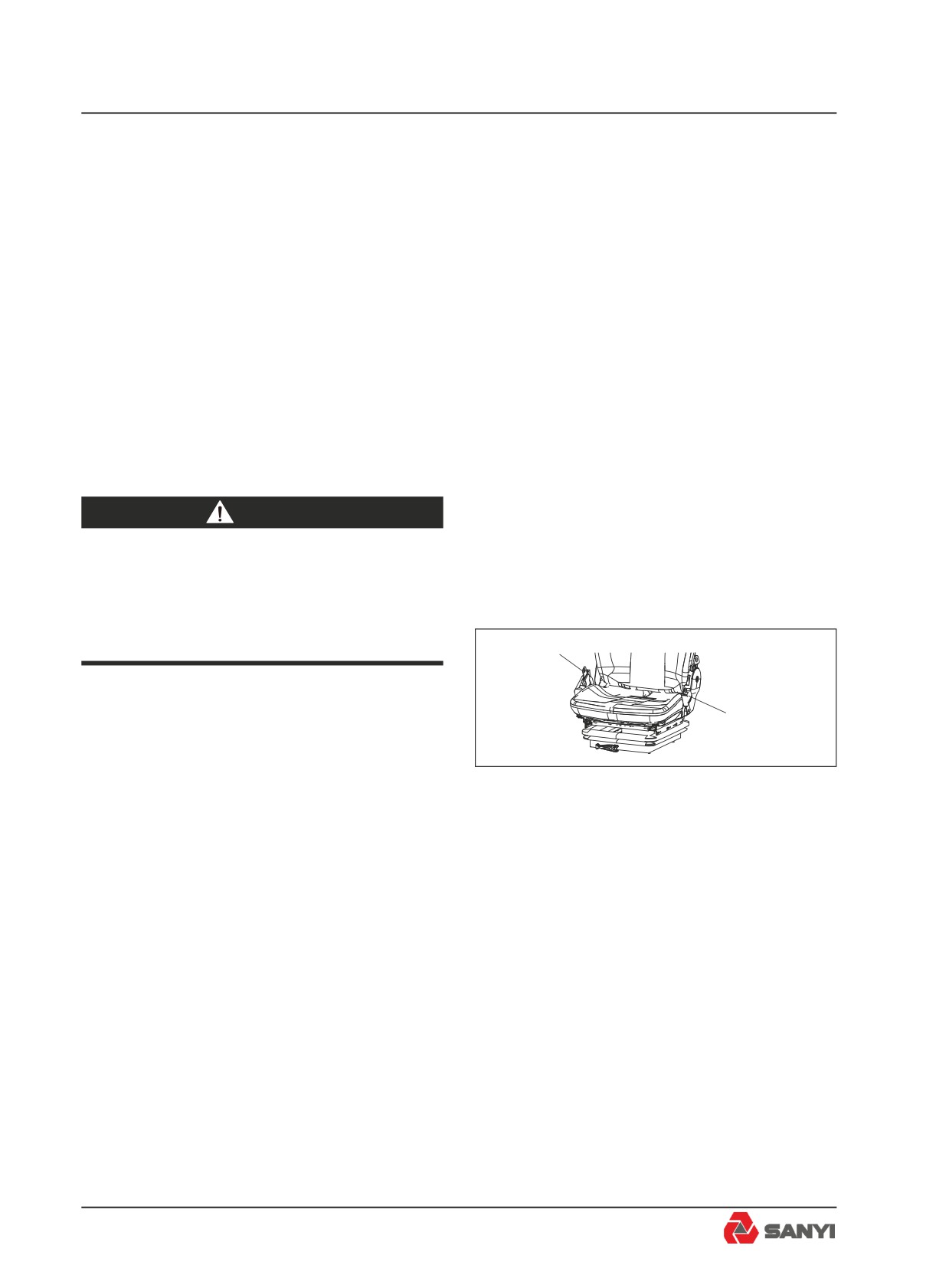
Controls and Operating
Turning the adjusting handle (1) clockwise will
bring you a hard suspension which is suitable
for heavy operator; turning the adjusting
handle (1) counterclockwise will bring you
a soft suspension which is suitable for light
operator.
Remark: To achieve the best adjustment,
adjust the reading (kg) on the green indication
belt to weight of operator, which is on the left
side of the adjusting handle.
Adjustment scope: 50Kg-130Kg
5. Headrest height adjustment
Adjust headrest up and down.
Adjustment scope: 105mm (see Fig 3-8)..
warning
Do not attempt to adjust the seat or
seat belt while the machine is moving.
Loss of control may result. Stop the
machine; apply the brakes;then adjust.
1
3.9 Seat Belt
2
Adjust the seat to the best height which does
not affect the driving. Completely release the
Fig 3-9
seat belt (1), sit down on the seat, pull out seat
belt (1), and buckle up lock catch (2). In order
to remove the seat belt, press the button on
lock catch (2) to pop up seat belt (1) (see Fig
3-9).
3-12
Controls and Operating
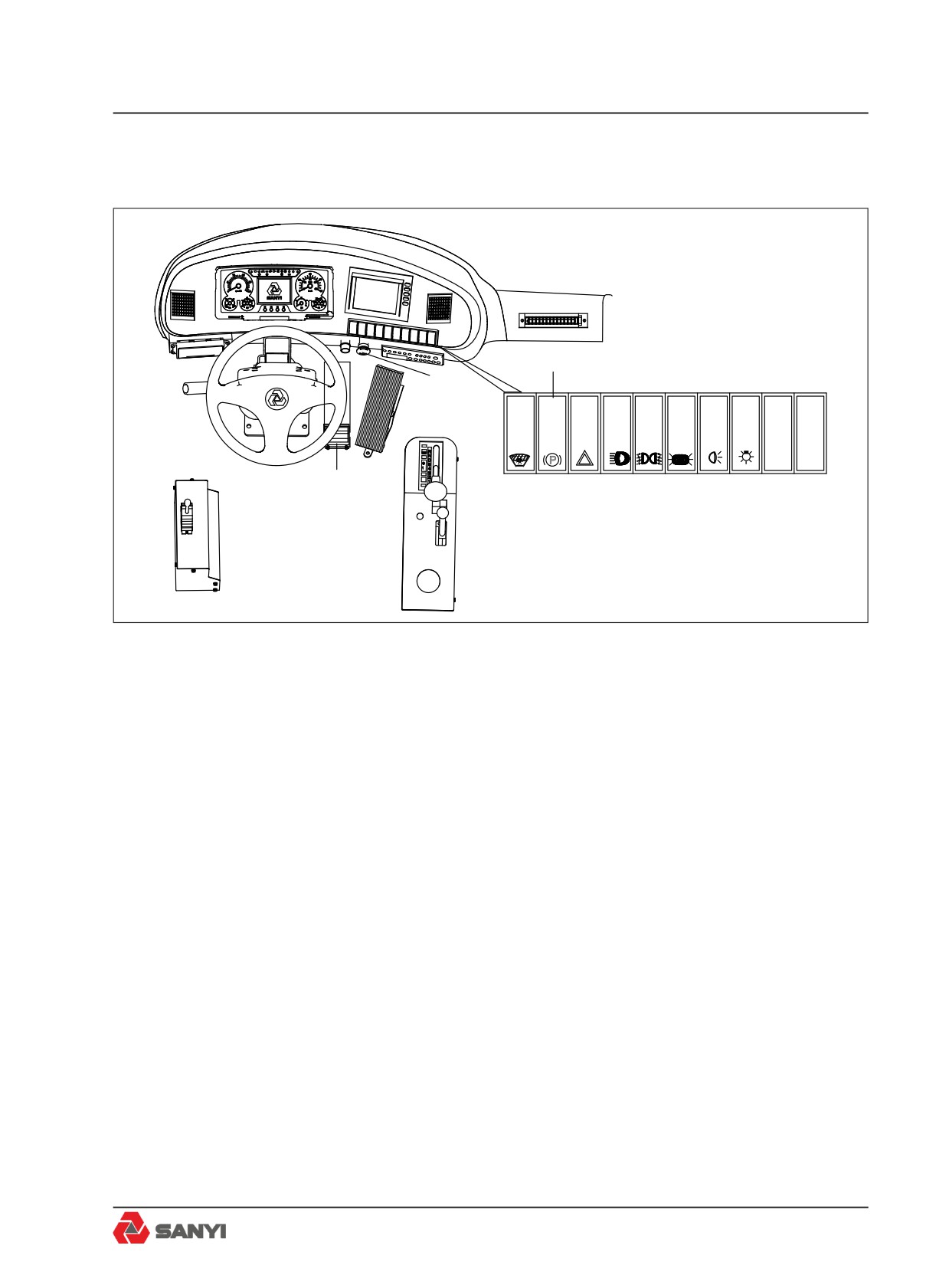
3.10 Truck Controls
!
!
Parking brake switch
Ernergency
brake switch
P
Foot pedal
Fig 3.10
3.10.1 Braking
The truck is provided with following brake
methods: Service brake, parking brake,
emergency brake, retarder, which can be
selected according to the actual condition.
Use service brake during normal operation;
Use parking brake during stopping; Use
emergency brake in an emergency. A
continuous braking force to hold the truck to a
safe steady speed.
3.10.2 Service Brake
This is a floor mounted pedal operated by the
right foot. Depress the pedal as required by
speed, load and road conditions to slow or
stop the machine. Release the pedal as the
machine slows until, when stopped, the pedal
is depressed just enough to hold it stationary.
(see Figure 3-10).
3-13
Controls and Operating
3.10.3 Parking Brake
Pushing the control in will apply the spring
operated parking brakes within the rear brake
assemblies and the rear service brakes. The
front service brakes will not apply when the
parking brake control is operated.
warning
Always apply the parking brake before
leaving the operator's seat.
3.10.4 Emergency brake
Pushing the control switch in an emergency.
To release the brakes, turn the control
clockwise.
Note:Try to avoid using the control switch.
For normal braking the service brake pedal
should be employed.
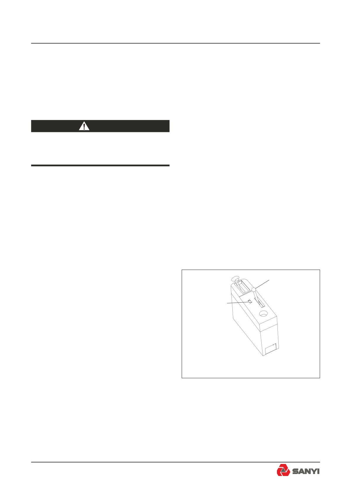
3.10.5 Retarder
Refer to Fig3-11, this truck is equipped with
2
two retarders: the transmission retarder and
the rear disk brake retarder. The handle (2) is
used to control the rear disk brake retarder.
1
The transmission retarder switch (1) is used to
control the transmission retarder.
Retardation is the term used for applying a
continuous braking force to hold the truck
to a safe steady speed when descending
grades. The retarder may be used anytime
to slow down. If additional braking is required
apply the service brakes. The retarder is not
meant for bringing the machine to a halt, or
Fig.3-11
for sudden deceleration - the service brakes
should be employed for this purpose.
When the retarder is applied, the ' Retarder
Indicator Light ' on the instrument panel will
illuminate and an orange coloured warning
light at the rear of the truck will illuminate to
warn following trucks.
3-14
Controls and Operating
The retarder is off when the lever is fully
forward and is applied as the lever is pulled
back. Rear disc brake retarder can obtain
different retardation by shifting handle from
front to rear. Maximum retardation is obtained
when the lever is in the fully back position.
(1) Retarder Operation
Before the machine crests the top of a grade
and starts down, the operator should slow the
machine with the service brakes and downshift
to the gear range which would be used to
ascend the grade. The retarder should be
applied before starting the descent. Machine
downgrade speed (with the retarder applied
as required) in the gear range selected should
be high enough to keep the engine operating
at governed speed with the throttle closed
(operator's foot off the accelerator pedal).
This will ensure maximum oil circulation and
cooling. If the rate of descent is too slow, the
transmission should be upshifted to the next
highest gear range. If the rate of descent is too
fast, the gear range selected is too high and
the operator must slow the machine by using
the service brakes, then downshift into a lower
gear range which will allow a safe descent and
efficient retarder operation.
The two retarders can be used at the same
time, it is strongly recommended that just one
of them is used and the transmission retarder
is prior. Only when maximum transmission
retardation is obtained and additional
retardation is required, the rear disk brake
retarder be used.
Note: In order to obtain the maximum
retardation and cooling effect during
retardation, the engine speed should be
maintained as high as possible without
exceeding the maximum recommendation.
(2) Oil Temperature - Rear Disc Brake
The disc brake hydraulic temperature warning
light on the instrument panel will illuminate
and an electric horn will sound if the oil flowing
3-15
Controls and Operating
through the disc brake assemblies overheats.
If alarm is activated, reduce downgrade travel
speed. If the trouble persists, stop the machine
and have the fault corrected.
(3) Oil Temperature - Transmission
During normal operation the transmission oil
temperature gauge should read in the green
zone. However, during transmission retarder
operation oil temperature can enter the yellow
' RETARDER ON ' zone but should not enter
the red zone. Do not allow the temperature
to stay at or near the top of the yellow zone
for more than 3 minutes. Reduce downgrade
travel speed to avoid the oil overheating and
possible damage to the transmission.
warning
Great care should be used if applying
the retarder when road surfaces are
slippery. Retarder braking effect will
occur only at the driving axle and
could make truck control difficult.
3.11 Engine
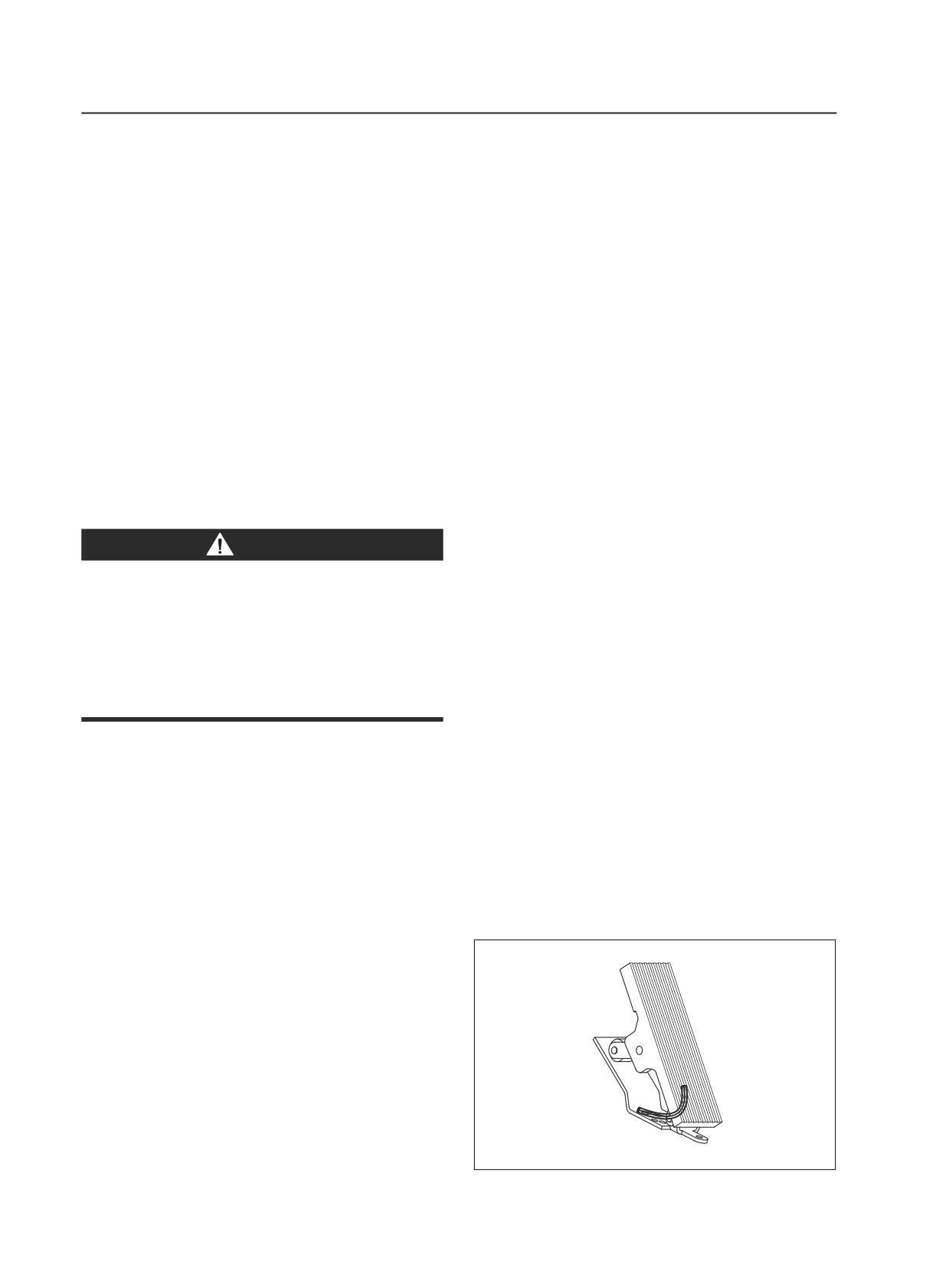
3.11.1 Electronic Foot Pedal
The electronic foot pedal provides an electrical
signal to the engine's fuel control system in
proportion to the degree of pedal actuation.
(see Fig3-12).
Note: The electronically controlled engine
will override the electronic foot pedal position
until the engine is warmed up to the correct
operating temperature. The engine MUST
be started with foot 'OFF' the electronic foot
pedal.
Fig.3-12
3-16
Controls and Operating
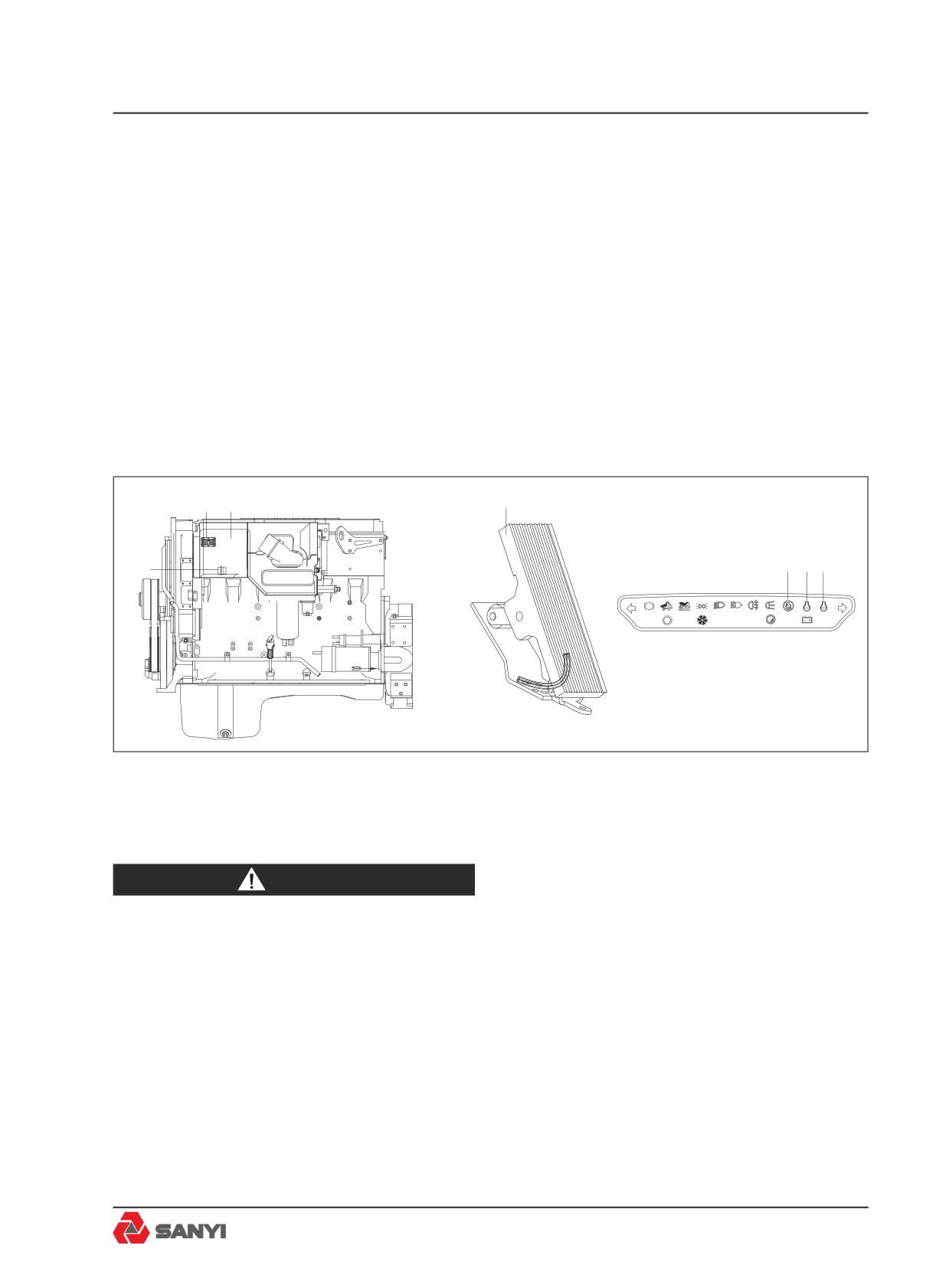
3.11.2 Quantum electronic fuel system
This machine is equipped with the Quantum
Electronic Fuel System, an electronic engine
control system, which continually monitors
the engine and warns the operator when a
problem develops. The system also takes
action to prevent damage to the engine and,
provides the serviceman with diagnostic
capabilities so that problems can be corrected
quickly and easily.
2
1
4
5
6
7
3
P
!
!
Fig.3-13
1.Electronic Control Module (ECM)
5. Stop light
2&3. Harness connector (31 and 21pin RHS)
6. Maintenance indicator
4.Electronic Foot Pedal
7. Warning light
warning
Before any welding is done on a
machine equipped with the Quantum
Electronic Fuel System, disconnect the
following in this order:
Battery earth cable, battery supply
cable, alternator earth cables,
alternator supply cables, transmission
black box connector, ECM interface
harness connector (30 pin RHS), ECM
power harness connector (5 pin RHS)
and ECM sensor harness connector
3-17
Controls and Operating
(30 pin LHS). Turn off ignition key
switch to isolate the batteries before
disconnecting any components.
After welding connect all of the above
in the reverse order.
3.11.3 Quantum electronic fuel system -
description
1. Electronic Control Module (ECM)
Receives electronic inputs from the driver as
well as from mounted sensors that provide
informationelectronically, such as oil pressure
and temperature and intake manifold pressure.
This information is used to control both the
quantity of fuel injected and injection timing.
2. Programmable Read Only Memory
Located in the ECM and encoded with the
operating software. Additional information
is programmed into the EEPROM. This
information controls the horsepower rating,
torque curve, maximum engine speed and
engine protection devices. The ECM processes
this information and sends electronic signals
to the Electronic Fuel System Injectors where
the precise amount of fuel is injected into the
engine.
3.Electronic Fuel System Injectors
The injector is a lightweight, compact unit that
injects diesel fuel directly into the combustion
chamber. The amount of fuel injected and the
beginning of injection timing is determined by
the ECM. The ECM sends a command pulse
which activates the injector solenoid.
The injector performs four functions:
a - Creates the high fuel pressure required for
efficient injection.
b - Meters and injects the exact amount of fuel
required to handle the load.
c - Atomizes the fuel for mixing with the air in
the combustion chamber.
d - Permits continuous fuel flow for component
cooling.
3-18