Kobelco SK160LC-6E / ED190 / SK210LC-6E / SK250LC-6E / SK290LC-6E / SK330LC-6E. Service Manual - page 13


  Index      Manuals     Kobelco SK160LC-6E / ED190 / SK210LC-6E / SK250LC-6E / SK290LC-6E / SK330LC-6E. Service Manual (2002)


Search            copyright infringement  


Content      ..     11      12      13      14     ..


Kobelco SK160LC-6E / ED190 / SK210LC-6E / SK250LC-6E / SK290LC-6E / SK330LC-6E. Service Manual - page 13


Pump Regulator Back-up Function ( Except SK160/ED190 )
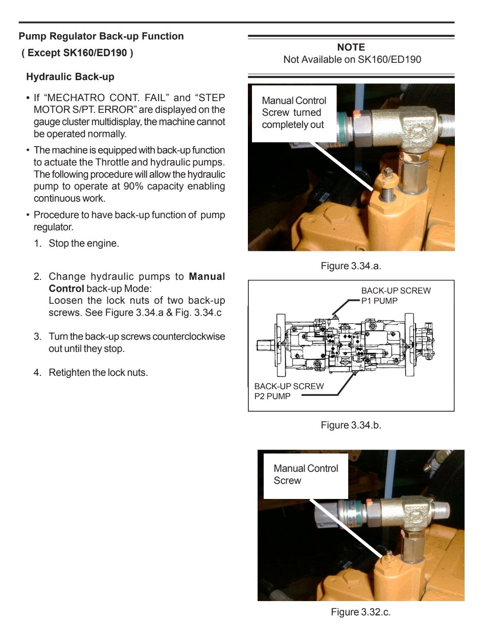
 

Back-up function - cont.
Engine Speed Control Cable


4. Place throttle at low idle. Start the engine.

5. To increase engine speed, press the center button of engine control knob, and simultaneously pull cable control to raise the engine speed to to be maintained.

(See Figure 3.35.a)

6. Resume working

7. After finishing the work, press the center button of engine control cable and concurrently push down the knob, and the engine speed returns to low idling.

8. Stop the engine by pulling the emergency stop cable, then turn off the keyswitch.


3. Power Boost Switch - FIGURE З.Зб.а


6. 12 Volt Power Supply-FIGURE 3.37.a


3. Safety Lock Lever - FIGURE 2.38.a


4. Adjustment of Pilot Control Levers Height -FIGURE 2.38.b

To adjust the height of the pilot control levers, use a 17 mm wrench and remove capscrew (M10)under the operator console. The 3-stage setting hole position is as follows:

a. From factory,the hole is set to the medium position (H1).

b. If it is set to the medium position (H1), the valve height is raised 10mm (0.4”).

c. When it is set to the lowest position (H2), the height is raised max.20mm (0.8 ”).


GAUGE CLUSTER

The monitor displays information sent from sensors positioned at various places on the excavator, making it possible to monitor the excavator’s operating working conditions.


5.How to Calibrate the Engine Oil Change Interval.


L.С.D.Display


В. Warning Displays


6. ENGINE OIL PRESSURE ICON


19. ATTACHMENT BOOST PRESSURE ICON


The following chart s aimed at familiarizing personnel with the priority of the Gauge Cluster Display Icons.Pay close attention to these icons as they can aid in avoiding unnecessary repairs and expense.
The icons in the chart below are listed in priority from the most serious to least serious. EXAMPLE:lf the engine oil pressure is abnormal and Fuel level s low, the engine oil pressure Icon will display and buzzer will sound. After the oil pressure is back to safe operating pressure, the low fuel Icon will display.


Content      ..     11      12      13      14     ..