Kobelco SK160LC-6E / ED190 / SK210LC-6E / SK250LC-6E / SK290LC-6E / SK330LC-6E. Service Manual - page 12


  Index      Manuals     Kobelco SK160LC-6E / ED190 / SK210LC-6E / SK250LC-6E / SK290LC-6E / SK330LC-6E. Service Manual (2002)


Search            copyright infringement  


Content      ..     10      11      12      13     ..


Kobelco SK160LC-6E / ED190 / SK210LC-6E / SK250LC-6E / SK290LC-6E / SK330LC-6E. Service Manual - page 12


LEFT HAND OPERATOR CONSOLE
1. Climate Control Air Conditioner FIGURE 3.17a and 3.17.b


The climate control-АС provides a comfortable indoor environment and adjustable control of cab temperature. It removes moisture from humid air and reducing window glass fogging. The climate control-ACis installed behind operator’s seat and sends cold air or hot air into cab.


SUPPLEMENTARY EXPLANATION

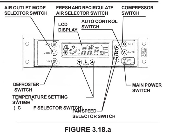
The LCD display indicates temperature, air outlet mode, compressor ON - OFF, AUTO recirculate and fresh air and fan speed. Each switch, fan mark of blower, and TEMP mark are illuminated green at night.


AC - Fundamental Use - FIGURE 3.18.b

Before turning air-conditioner on, close doors of cab and windows to achieve the best perormance.
a. Press control switch AUTO to control air capacity and blower outlet atomatically, and set the temperature in the range from 18.5 °C (65.3 °F) to 31.5 °C (88.7°F). The outlet temperature, outlet opening and fan speed are adjusted automatically so that indoor temperature of cab comes closer to the set temperature.

b. Select proper mode manually through recirculate and fresh air capacity selector switch and compressor switch ON -OFF.
c. Select preferable fan speed manually through fan speed selector switch when fan speed,selected through auto control, isnot preferable. The indicator lamp of AUTO ” n LCD display goes out. Press “AUTO "switch to return to automatic climate control.


Control Panel Functions

Main Power Switch and Display FIGURE 3.18.a


a. LCD display is illuminated when the climate control-АС is operating. When the climate control-АС is stopped, LCD will be turned off.

b. Press main power switch,and all functions for the climate control-АС switch ON or OFF.

Each time when this switch is pressed, the function switches ON and OFF. When switched ON,the climate control-AC starts operating at the point set before switching OFF (When it is set to AUTO, auto mode; if NORMAL is selected, then in normal mode).


NOTE

The key switch will switch air-conditioner OFF, but the operating condition just before switching off may not be restored when the key switch is
turned ON again.


Auto Control Switch and Display FIGURE 3.19.b

a. Press the main power switch to activate the climate control-АС and the LCD display will illuminate.

b. Press control switch AUTO, and fan speed and air outlet are automatically controlled, and “AUTO ” indicator lamp on LCD display is illuminated.

c. When the main power switch is OFF, the system will retain the previous setting in memory. Therefore, when the main power switch is pressed again, the climate control AC will come on in the auto control mode. In the Auto mode, the fan speed and air outlet openings are operated automatically.


Temperature Setting Switch and Display FIG-URE 3.20.a


a. The set temperature is ndicated indigits on LCD display.Temperature set range is 18.5 °C (65.3 °F) to 31.5 °C (88.7 °F).

b. Press the two temperature set switches simultaneously for 5 seconds to change the display from Centigrade (°C) to Fahrenheit (°F) or viceversa in the LCD display. (Eg.) 5°C (77 °F) or (77 °F) 25 °C.

c. Press temperature set switch DOWN or UP to change the set temperature. The temerature goes up or down by 0.5 °C (0.9 °F) in graduation.

d. The set temperature 18 °C (64.4 °F) is the lowest cooling temperature, and 32 °C (89.6°F) is the highest heating temperature. Control beyond either of these limits is not possible.


Air Outlet Mode Selector Switch and Display FIGURE 3.20.b


Defroster Switch and Display FIGURE 3.21 .a


2. Auto Warm Up System-FIGURE 3.28.a


3. Travel Speed Select Switch FIGURE 3.29.a


4. Independent Travel Switch - FIGURE - 3.29.a


5. Heavy Lift Switch -FIGURE 2.30.a


SK480 Engine Diagnosis Lamps
(Red and Amber) - FIGURE 2.29.A, 2.29.В


2. KPSS Release Switch - FIGURE 3.32.a


2. Engine Speed Control Cable - FIGURE 2.33.a


Content      ..     10      11      12      13     ..