Kobelco SK160LC-6E / ED190 / SK210LC-6E / SK250LC-6E / SK290LC-6E / SK330LC-6E. Service Manual - page 4


  Index      Manuals     Kobelco SK160LC-6E / ED190 / SK210LC-6E / SK250LC-6E / SK290LC-6E / SK330LC-6E. Service Manual (2002)


Search            copyright infringement  


Content      ..     2      3      4      5     ..


Kobelco SK160LC-6E / ED190 / SK210LC-6E / SK250LC-6E / SK290LC-6E / SK330LC-6E. Service Manual - page 4


NOTE

The key switch will switch air-conditioner OFF, but the operating condition just before switching off may not be restored when the key switch is turned ON again.
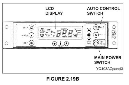
2. Auto Control Switch and Display - FIGURE

2.19B

a. Press the main power switch to activate the climate control-АС and the LCD display will illuminate.

b. Press control switch AUTO, and fan speed and air outlet are automatically controlled, and “AUTO” indicator lamp on LCD display is illuminated.

c. When the main power switch is OFF, the system will retain the previous setting in memory. Therefore, when the main power switch is pressed again, the climate control AC will come on in the auto control mode. In the Auto mode, the fan speed and air outlet openings are operated automatically.
 

3 Temperature Setting Switch and Display -FIGURE 2.19C


5. Defroster Switch and Display - FIGURE 2.20B


7. Compressor Switch and Display - FIGURE 2.21 A


В2. Horn switch -FIGURE 2.21C


В4. Auto Warm Up Selector Switch - FIGURE 2.22A

Before turning the ignition switch to the ON postion, turn on the warm up switch located on the left panel and then start the engine.
NOTE

The Auto Warm Up System will not activate if the Ambient temperature is above 10 °C (50 °F).
1. Warming up of engine

The “WARMING UP” is displayed on the multi display after operating the engine for 3 minutes at auto accel speed (1050 rpm.) when the accel dial set value is the value for deceleration or lower, the engine speed returns to the speed set by the the throttle potentiometer.

2. Warming of hydraulic oil

The warm up operation will be done as follows: pump max. flow rate at the engine speed (1050 rpm) for 3 minutes _> pump max. flow rate (control valve closed) at the engine speed (1600 rpm) for 5 minutes _> pump max. flow rate and control valve fully open at the engine speed (1600 rpm) for 5 minutes max. flow rate at the engine auto accel speed (1050 rpm) for 10 minutes, “WARMING UP” is displayed on the multidisplay.


3. Warming up complete

After an elapsed time of about 26 minutes of warming of hydraulic oil, or when the hydraulic oil temperature switch turns OFF, The WARMING UP indication (”WARMING UP”) on the multidisplay disappears and the buzzer sounds for 5 seconds. Turn the auto warm up switch OFF.
NOTE

1. If a pilot control lever is activated while the warm up system is active, the warm up system is disconnected. The warm up system will restart after 10 sec. of neutral condition in the pilot control system.

2. If the Auto warm up switch is pressed to the OFF position, the warm up system is disconnected.

3. In climates below -18 °C (0 °F) it may be necessary to use a coolant heater, fuel heater, engine heater jacket and/or additional battery power to aid in starting the engine.

CAUTION
AUTO WARM-UP SHOULD BE UTILIZED ANYTIME MACHINE IS STARTED IN CLIMATE TEMPERATURES BELOW 10 °C (50 °F) TO STABILIZE MACHINE CONTROL RESPONSE. COLD OIL CAN CAUSE ERRATIC MACHINE OPERATION.


В5. Independent Travel Select Switch - FIGURE 2.23A

В6. Heavy Lift Switch - FIGURE 2.23B


С. REAR PANELAND OTHERS

C1. Swing Parking Brake Release Switch and Hydraulic Back Up System


С2. 12 Volt Power Supply - FIGURE 2.25A

The 12 volt power supply is located beside the right side switch panel.

For use of common auto accessories such as a fan or other accessories requiring 12 volt(DC) power, pull cover away from 12 volt power supply and insert 12 volt male socket into power supply. Replace cover after use.

CAUTION

Do not use the cigarette lighter as a power source for 12 volt accessories. It is a 24 volt outlet. Plugging a 12 volt accessory into a 24 volt connector may result in shorting and/or Fire.

MAXIMUM CONTINUOUS OUTPUT - 180 Watt


СЗ. Fuse Box-FIGURE 2.25В


D. OPERATING LEVERS AND CONTROLS

D1. Engine Emergency Stop Control - FIGURE 2.26A

The engine emergency stop control cable is located at the lower right hand side of the operator’s seat. It is used only in an emergency situation to stop the engine quickly. It has 2 operating positions.

1. “IN”-Releases the fuel stop lever on the governor to allow normal starting of the engine.

2. “OUT”-Activates the fuel stop lever on the engine governor to immediately stop the engine.

CAUTION

Do Not suddenly stop the engine when operating at high RPM. Doing so may damage the turbo or engine.
 

D2. Left Hand Operator Control Lever - FIGURE 2.26B
A CAUTION

Hydraulic controls are designed for and set to ISO operating pattern for optimum machine performance and safety. Changing the control pattern will effect the performance of the machine.

The left hand operator control lever is located at the top front of the L.H. operator console. Its purpose is to allow the operator to control operations of the swing and arm. Operating speed of function is variable from stop to full stroke depending on how far lever is operated. The left hand operato control lever has 4 basic operational functions.

1. “FORWARD”- Variable speed arm out.


Content      ..     2      3      4      5     ..