Api Pneumatic. GENERAL CATALOG (2019) - page 34
 

  Index      Manuals     Api Pneumatic. GENERAL CATALOG (2019)


Search            copyright infringement  


Content      ..     32      33      34      35     ..


Api Pneumatic. GENERAL CATALOG (2019) - page 34


5

5.1.1

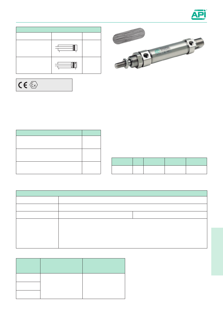
Stainless Steel cylinders ISO 6432

Bores from 16 to 25 mm


Double acting

Series of stainless steel cylinders conforming to ISO 6432 
standards.
The heads are connected with the tube through rolling; this 
guarantees perfect tightening.
The cushionings are in nitrile rubber to relieve the impact of the 
piston.
One or more magnetic reed switches can be applied to the 
magnetic type.
For the magnetic reed switches type ASV see from page 1.110.1.
For mounting accessories see from page 5.30.1.
For rod clevis see from page 5.20.1.

How to order: 20/50 MDMXP

The options can be combined (when this is possible).

See page 1.1.3 to calculate the cylinder force.
Seal kits not available for these cylinders.

On request, they can be supplied

according to 2014/34/EU - 

ATEX

II 2Gc IIC T5
II 2Dc T100°C

Technical data

Fluid

Compressed filtered air with or without lubrication. Lubrication, if started, must be continued.

Pressure

max 10 bar

Temperature range

-20°C ÷ + 80°C (standard)

-20°C ÷ +150°C (V)

Materials

Heads:

Barrel:

Rod:

Seal:

Bushing:

Piston: 

Stainless steel AISI 304

Stainless steel AISI 304

Stainless steel AISI 304

Polyurethane

Sintered bronze

Brass

Standard executions

Version

Symbol

Type

Magnetic

MDMX

Magnetic with adjustable 
cushionings 
(bore from 20 to 25 mm)

MDMAX

Options 

Suffix

Through rod

P

Seals FKM

      -20°C ÷ +150°C 

V

Special version on request

/ S

20

/

50

MDMX

P

Bore

/

Stroke

Type

Option

Bore 

(mm)

Corse standard 

(mm)

Maximum stroke 

(mm)

16

10, 25, 50, 80, 
100, 125, 160, 
200, 250, 320, 

400, 500

1000

20

25

Stainless Steel

5.1.2

Stainless Steel cylinders ISO 6432

Bores from 16 to 25 mm


Double acting

For dimensions and codes of the accessories see page 5.30.1

Type: 

MDMXP-MDMAXP

+ stroke

V

G + stroke

L + stroke

L

1

 + stroke

M + stroke

Type: 

MDMX-MDMAX

AF + stroke

Flange

PO + stroke

PA + stroke

High foot

NF + stroke

Rear clevis

L + stroke

L

1

 + stroke

ø mm

L

L

1

C

C

1

C

2

S

S

1

V

K

16

74,5

96,5

M5

M16x1,5

M6

5

10

6

16

20

92

116

1/8”

M22x1,5

M8

7

13

8

20

25

97

125

1/8”

M22x1,5 M10x1,25

9

17

10

22

ø mm

AF

HC

P

P

1

P

2

PA

PD

PL

PO

T

VO

N

16

82

27

20

14

6

92

32

4

84

4

20

18

20

97

30

25

17

8

109

36

5

102

5

25

19

25

102,5

30

25

17

8

114,5

40

5

103,5

5

25

23

Ø 

mm

C2

V

1

C

1

R KL

1

R

1

V

D CL

1

L

1

L

M G

1

A

1

CL

A

M

1

S

C

G

K

H

H

1

S

1

16

M6

6

M16x1,5

20

12 17,27 19

6

16

82

96 46 56 22 18

27

9

5

M5

112 24

6

3

10

20

M8

8

M22x1,5

27

16 21,27 25,5 8

20

95 111 51 67 24 20

32

12 7

1/8” 131 27

8

4

13

25

M10x1,25

10

M22x1,5

30

16

26,5

28

8

22 104 118 52 67 29 22

37

12 9

1/8” 140 27

8

5

17

5

5.5.1

Stainless Steel Cylinders ISO 15552

Bores from 32 to 200 mm


Double acting

New series of stainless steel 316 L cylinders conforming to 
ISO15552.
Round tube and external tie-rods, standard with adjustable 
cushionings.
Scraper ring in polyurethane specially developed for chemical 
and food industries.
The main features of this cylinder are the “clean” modern design 
and the attention to details. 
A particular attention has been given to the manufacture of the 
end caps; there are no external casting cavities, thus eliminating 
contamination traps.
In order to facilitate the replacement of the piston rod seal the 
nose has been developed for simple maintenances also on 
cylinders still mounted on a machine.

For the magnetic reed switches type ASV see from page 1.110.1.
For coupling cylinders/reed swiches/brackets see table on page 
1.120.5
For mounting accessories see from page 5.40.1
For rod accessories see from page 5.20.1.

The options can be combined (when this is possible).
The suffix of the options are to be added to the model number of the standard product, as shown in the following table. 
How to order: 63 / 100 AMXPVR-M12x1,25

On request, they can be supplied

according to 2014/34/EU - 

ATEX

II 2Gc IIC T5
II 2Dc T100°C

63

/

100

AMX

P

V

R-M12X1,25

Bore

/

Stroke

Type

Option

Option

Option

Options

Suffix

Through rod (pag. 5.5.4)

P

Seals FKM -20°C ÷ +150°C

V

Scraper ring only FKM -20°C ÷ +80°C 

V1

Low temperature seals -40°C ÷ +80°C 

BT

Tandem forward movement piston rods coupled together   (pag. 5.5.5)

TA1

Tandem forward movement piston rods independent   (pag. 5.5.5)

TA2

Tandem back to back   (pag. 5.5.5)

TA3

Tandem front to front  (pag. 5.5.5)

TA4

Extended rod (indicate the requested WH dimension in mm. E.g.: WH -100)

WH-...

Without adjustable cushionings

D

Adjustable rear cushioning only

D1

Adjustable front cushioning only

D2

Special male thread (indicate the requested thread. E.g. : R-M 10x1,5). 
The dimension AM of the special thread will be the same as the standard. The cylinder will be supplied without rod nut.

R-M...

Female thread; for dimensions see page 5.5.4

F

With bellows for protection of the rod (in this case the dimension WH will be extended according the stroke of the cylinder)

Z

NBR seals

H

Piston rod scraping ring in nitrile rubber NBR

H1

Special on request

/S

Standard executions

Version

Symbol

Type

Magnetic Standard 

AMX

Lubrication with synthetic grease long lasting 
for applications with low start up, granting low 
friction and a permanent lubrication film.
Fully composed by non-toxic elements 
conforming to directive FDA section 21 CFR 178 
about accidental contact with food ( registered 
NSF H1 ).

Stainless Steel

5.5.2

Stainless Steel Cylinde

rs ISO 15552

Bores from 32 to 200 mm


Technical data

Technical data

Bore (mm)

32

40

50

63

80

100

125

160

200

Fluid

Compressed filtered air with or without lubrication. Lubrication, if started, must be continued.

Pressure

0,5 ÷ 10 bar

Temperature range

-20°C ÷ +80°C (standard /V1)

-20°C ÷ +150°C (V)

-40°C ÷ +80°C (BT)

Stroke

from 10 mm to 2500 mm

Cushion lenght

20

22

25

25

35

35

35

48

48

Ports

1/8”

1/4”

3/8”

1/2”

3/4”

Rod thread

M10 x 1,25 M12 x 1,25

M16 x 1,5

M20 x 1,5

M27 x 2

M36 x 2

Weight

Stroke zero (g)

860

1350

2290

2940

4960

7030

12730

24780

31320

Additional 10 mm 
Stroke (g)

27

35

61

66

106

116

214

331

478

Materials (standard types)

1

Tube and tie-rods

Stainless steel AISI 316L

2

Heads

Stainless steel AISI 316L

3

Rod

Stainless steel AISI 316L, lapped

4

Piston

Die-cast aluminium

5

Bushing

Self-lubricating sintered bronze

6

Guide ring

Natural Delrin

7

Rod seals

Special polyurethane

8

Disassembling nose

Stainless steel AISI 316L

9

Group cushioning screw

Stainless steel AISI 316L

Other seals

Nitrile rubber NBR/polyurethane

5

5.5.3

Stainless Steel Cylinders ISO 15552

Bores from 32 to 200 mm


Standard dimensions

ZJ+stroke

AM

WH

L2+stroke

VA

L1

PL

L7

ØB

J3

J2

KK

ØMM

ØB

VD

TG

E

E

TG

BG

RT

EE

Type: 

AMX

Ø (mm)

L7

MM 

Ø f7

PL

RT

TG

VA

VD

WH

ZJ

1

2

3

32

17.5

12

10

M6

32,5

4

4

26

124

10

17

27

40

21.5

16

15

M6

38

4

4

30

139

13

19

32

50

20

20

15

M8

46,5

4

4

37

147

17

24

36

63

20

20

16

M8

56,5

4

4

37

162

17

24

38

80

27

25

20

M10

72

4

4

46

178

22

30

42

100

28.5

25

23.5

M10

89

4

4

51

193

22

30

50

125

31.5

32

23.5

M12

110

5

5

65

230

27

41

52

160

33

40

27.5

M16

140

6

8

80

266

36

55

60

200

35

40

27

M16

175

6

8

95

281

36

55

70

Ø 

(mm)

AM

Ø d11

BG

E

EE

J2

J3

KK

L1

L2

H

32

22

30

15

47

G1/8

6

5

M10x1,25

20

94

8

40

24

35

15

52

G1/4

7.5

5

M12x1,25

22

105

6

50

32

40

16

65

G1/4

9.5

7,5

M16x1,5

26

106

8

63

32

45

16

75

G3/8

13.5

4

M16x1,5

25

121

8

80

40

45

17

95

G3/8

13.5

6

M20x1,5

32

128

10

100

40

55

17

115

G1/2

15

6

M20x1,5

38

138

10

125

54

60

21

140

G1/2

17

8

M27x2

40

160

14

160

72

65

24

180

G3/4

17

15

M36x2

50

180

14

200

72

75

24

220

G3/4

17

15

M36x2

65

180

14

5.5.4

Stainless Steel Cylinders ISO 15552

Bores from 32 to 200 mm


Options

ZJ +Stroke

ZM +2Strokes

Type: 

...P

Type: 

...F

Ø 

mm

AF

KF

T4

WF

GF

ZJ

ZM

32

12

M6

2,6

26

8

120

146

40

12

M8

3,3

30

10

135

165

50

16

M10

4,7

37

12

143

180

63

16

M10

4,7

37

12

158

195

80

20

M12

6,1

46

14

174

220

100

20

M12

6,1

51

14

189

240

125

32

M16

8

65

18

225

290

160

36

M20

10

80

22

260

340

200

36

M20

10

95

22

275

370

5

Stainless Steel Cylinders ISO 15552

Bores from 32 to 200 mm


Options

Type: 

...TA1

Type: 

...TA2

Type: 

...TA3

Type: 

...TA4

5.5.5

Ø 

mm

AM

B

C

D

L8

WH

32

22

40

12

48

94

26

40

24

44

12

54

105

30

50

32

52

16

69

106

37

63

32

50

16

69

121

37

80

40

64

20

86

128

46

100

40

76

20

91

138

51

125

54

80

35

120

160

65

160

72

100

50

152

180

80

200

72

130

50

167

180

95

L8 + stroke 1

AM

WH

B

L8 + stroke 2

stroke 1

stroke 2

L8 + stroke 1

AM

WH

B

L8 + stroke 2

AM

WH

L8 + stroke 1

L8 + stroke 2

C

AM

WH

L8 + stroke 1

L8 + stroke 2

D

5.5.6

Stainless Steel Cylinders ISO 15552

Bores from 32 to 200 mm


Mounting accessories  ISO 

XD + stroke

ZF + stroke

W

Rear clevis/eye

Flange

XA + stroke

SA + stroke

AH

XV max + stroke

max

XV min.

Feet

Centre trunnion

XD + stroke

B

XD + stroke

C

D

Rear standard hinge

Rear 90° hinge

For dimensions and codes of the accessories: see page 5.40.1

Ø 

mm

max

AH

B

C

D

SA

W

XA

XD

XV 

min

XV 

max

ZF

32

70

32

22

21

32

142

16

144

142

60

86

130

40

78

36

25

24

36

161

20

163

160

69

96

145

50

91

45

27

33

45

170

25

175

170

78

102

155

63

94

50

32

37

50

185

25

190

190

82

113

170

80

130

63

36

47

63

210

30

215

210

97

123

190

100

145

71

41

55

71

220

35

230

230

107

133

205

125

170

90

50

70

90

250

45

270

275

126,5

163,5

245

160

190

115

55

/

/

300

55

305

315

150

190

285

200

240

135

60

/

/

320

70

322,5

335

165

205

300

5

5.11.1

Stainless Steel Round Cylinders

Bores from 32 to 63 mm


Double acting

New series of stainless steel round cylinder with bores from 
32 to 63mm., characterized by an essential design specifically 
developed to prevent the settling of impurities.

Cylinder body is smooth surface free of chamfers or cavities 
where dirt can settle. 
This series is fully in Stainless Steel AISI 316L.

These features make RXD cylinders specifically suitable for 
Food&Beverage, Chemical, Pharmaceutical and Medical 
industries and for all those applications where maximum  hygiene 
and cleaning are required, even in corrosive environments.

RXD Series are available in several configurations bespoke 
solutions are also possible.

63

/

100

RXDVA

P

Bore

/

Stroke

Type

Option

Options

Suffix

Through rod

P

High temperature seals FKM (-20°C ÷ +150°C)

V

Scrape ring only in FKM (-20°C ÷ +80°C)

V1

Low temperature seals EPDM (-40°C ÷ +80°C)

BT

Extended rod (indicate the requested WH dimension in mm. E.g.: WH-100)

WH-

Without adjustable cushionings

D

Adjustable rear cushioning only

D1

Adjustable front cushioning only

D2

Special male thread (indicate the requested thread. E.g. : R-M 10x1,5).
The dimension AM of the special thread will be the same as the standard. The cylinder will be supplied without rod nut.

R-M

With bellows for protection of the rod (in this case the dimension WH will be extended according the stroke of the cylinder)

Z

Nitrile rubber NBR seals

H

Piston rod scraping ring in nitrile rubber NBR

H1

Special on request

/S

Standard executions

Version

Symbol

Type

Front threaded end cap 
mounting. 
Magnetic, adjustable 
cushioning

RXDVA

Front and rear threaded 
end caps mounting.
Magnetic, adjustable 
cushioning

RXDVD

Four threaded holes on 
rear cap. 
Magnetic, adjustable 
cushioning

RXDFP

Male hinge fixing (ISO 
MP4) 
Magnetic, adjustable 
cushioning

RXDCM

Male hinge with articulat-
ed head (ISO MP6) 
Magnetic, adjustable 
cushioning

RXDCS

Narrow female hinge 
(ISO AB6) 
Magnetic, adjustable 
cushioning

RXDCF

Hinge on front end cap. 
Magnetic, adjustable 
cushioning

RXDBA

Hinge on rear end cap. 
Magnetic, adjustable 
cushioning

RXDBP

Stainless Steel

Lubrication with synthetic grease long lasting for 
applications with low start up, granting low friction and 
a permanent lubrication film.
Fully composed by non-toxic elements conforming to 
directive FDA section 21 CFR 178 about accidental 
contact with food ( registered NSF H1 ).

For the magnetic reed switches type ASV  see from page 1.110.1
For mounting accessories 

see from page 5.35.1

For rod accessories 

see from page 5.20.1

II 2Gc IIC T5
II 2Dc T100°C

On request, they can be supplied according to 2014/34/EU - 

ATEX

The options can be combined (when this is possible).
The suffix of the options are to be added to the model number of the standard product, as shown in the following table.

How to order: 63 / 100 RXDVAP

5.11.2

1

2

2

3

4

5

6

7

8

Technical data

Bore (mm)

32

40

50

63

Fluid

Compressed filtered air with or without lubrication. Lubrication, if started, must be continued.

Pressure

0,5 ÷ 10 bar

Temperature range

Standard: -20 °C ÷ +80 °C
High temperature (V): -20°C ÷ +150°C
Scrape ring only in FKM (-20°C ÷ +80°C)
Low temperature (BT): -40°C ÷ +80°C

Stroke

from 10 mm to 1000 mm

Cushion lenght

20

22

25

25

Ports

1/8”

1/4”

3/8”

Rod thread

M10 x 1,25

M12 x 1,25

M16 x 1,5

Materials (standard types)

1

Tube and tie-rods

Stainless steel AISI 316L

2

Heads

Stainless steel AISI 316L

3

Rod

Stainless steel AISI 316L, lapped

4

Piston

Die-cast aluminium

5

Bushing

Self-lubricating sintered bronze

6

Guide ring

Natural Delrin

7

Rod seals

Special polyurethane

8

Group cushioning screw

Stainless steel AISI 316L

Other seals

Nitrile rubber NBR/polyurethane

Stainless Steel Round Cylinders

Bores from 32 to 63 mm


Technical data 

Type: 

RXDVA

5

5.11.3

Stainless Steel Round Cylinders

Bores from 32 to 63 mm


Standard dimensions

Type: 

RXDVA

ZJ + stroke

AM

WH

PL

PL

H

VB

ZA + stroke

ØB

ØMM

KK

CH1

CH2

CH3

EE

EE

ØD

U

49°

Ø

(mm)

AM

ØB

ØD

EE

KK

ØMM

f7

PL

VB

U

WH

ZA

+1
  0

ZJ

+1
  0

CH1

CH2

CH3

H

32

22

M30x1,5

36

G1/8 M10x1,25

12

10,5

20

26,5

26

94

120

10

29

17

5

40

24

M38x1,5

45

G1/4 M12x1,25

16

12

22

31

30

105

135

13

36

19

6

50

32

M45x1,5

54

G1/4

M16x1,5

20

11,5

26

39,5

37

106

143

17

42

24

8

63

32

M45x1,5

68

G3/8

M16x1,5

20

14,5

25

38,5

37

121

158

17

42

24

8

Type: 

RXDVD

ZJ + stroke

AM

WH

PL

PL

H

VB

VB

ZA + stroke

ØB

ØMM

KK

ØB

ØD

U

49°

CH1

CH2

CH3

CH2

EE

EE

49°

Ø

(mm)

AM

ØB

ØD

EE

KK

ØMM

f7

PL

VB

U

WH

ZA

+1
  0

ZJ

+1
  0

CH1

CH2

CH3

H

32

22

M30x1,5

36

G1/8 M10x1,25

12

10,5

20

26,5

26

94

140

10

29

17

5

40

24

M38x1,5

45

G1/4 M12x1,25

16

12

22

31

30

105

157

13

36

19

6

50

32

M45x1,5

54

G1/4

M16x1,5

20

11,5

26

39,5

37

106

169

17

42

24

8

63

32

M45x1,5

68

G3/8

M16x1,5

20

14,5

25

38,5

37

121

183

17

42

24

8

5.11.4

Stainless Steel Round Cylinders

Bores from 32 to 63 mm


Standard dimensions

Type: 

RXDFP

ZJ + stroke

AM

WH

PL

PL

H

VB

VD

BG

ZA + stroke

ØB

ØMM

KK

U

49°

CH1

CH2

CH3

EE

EE

ØD

TG

TG

RT

*

Ø

(mm)

AM

ØB

d11

BG

ØD

EE

KK

ØMM

f7

PL

RT

TG

VB

VD

U

WH

ZA

+1
  0

ZJ

+1
  0

CH1 CH2 CH3

H

32

22

30

6

36

G1/8 M10x1,25

12

10,5

M4

19

20

4

26,5

26

94

120

10

29

17

5

40

24

35

8

45

G1/4 M12x1,25

16

12

M5

24

22

4

31

30

105

135

13

33

19

6

50

32

40

9

54

G1/4 M16x1,5

20

11,5

M6

28

26

4

39,5

37

106

143

17

38

24

8

63

32

45

12

68

G3/8 M16x1,5

20

14,5

M8

35

25

4

38,5

37

121

158

17

42

24

8

Type: 

RXDCM

ZJ + stroke

AM

WH

PL

PH

H

VB

VD

ZA + stroke

ØB

ØMM

KK

U

49°

CH1

CH2

CH3

EE

EE

ØD

EW

LU

L

ØC

Ø

(mm)

AM

ØB

d11

ØC

H8

ØD

EE

EW

KK

ØMM

f7

L

LU

PH

PL

VB

VD

U

WH

ZA

+1
  0

ZJ

+1
  0

CH1 CH2 CH3

H

32

22

30

10

36

G1/8

26 M10x1,25

12

13

9

32,5 10,5

20

4

26,5

26

125

142

10

29

17

5

40

24

35

12

45

G1/4

28 M12x1,25

16

16

10

37

12

22

4

31

30

140

160

13

33

19

6

50

32

40

12

54

G1/4

32

M16x1,5

20

16,5

12

37

11,5

26

4

39,5

37

145

170

17

38

24

8

63

32

45

16

68

G3/8

40

M16x1,5

20

21

12

46

14,5

25

4

38,5

37

165

190

17

42

24

8

*For bore Ø 63 thread absent

5

5.11.5

Type: 

RXDCS

ZJ + stroke

AM

WH

PL

PH

H

VB

VD

ZA + stroke

ØB

ØMM

KK

U

49°

CH1

CH2

CH3

EE

EE

ØD

EW

LU

L

ØC

EP

α°

α°

Ø

(mm)

AM ØB

d11

ØC

H7

ØD

EE

EP EW

KK

ØMM

f7

L

LU

PH

PL

VB VD

U

WH

ZA

+1
  0

ZJ

+1
  0

CH1 CH2 CH3 H

α°

32

22

30

10

36 G1/8 10,5 14 M10x1,25

12

13

15 32,5 10,5 20

4 26,5 26

131

142

10

29

17

5 13

40

24

35

12

45 G1/4 12

16 M12x1,25

16

16

19

37

12

22

4

31

30

149

160

13

33

19

6 13

50

32

40

16

54 G1/4 15

21

M16x1,5

20

16,5 20,5 38,5 11,5 26

4 39,5 37 153,5 170

17

38

24

8 15

63

32

45

16

68 G3/8 15

21

M16x1,5

20

21

24 46,5 14,5 25

4 38,5 37

177

190

17

42

24

8 15

Type: 

RXDCF

ZJ + stroke

AM

WH

PL

PH

H

VB

VD

ZA + stroke

ØB

ØMM

KK

U

49°

CH1

CH2

CH3

EE

EE

ØD

LU

L

ØC

EW

EP

Ø

(mm)

AM ØB

d11

ØC

H8

ØD

EE

EP

EW

KK

ØMM

f7

L

LU

PH

PL

VB VD

U

WH

ZA

+1
  0

ZJ

+1
  0

CH1 CH2 CH3 H

32

22

30

10

36

G1/8

14

34

M10x1,25

12

16

9

32,5 10,5

20

4 26,5 26

125

142

10

29

17

5

40

24

35

12

45

G1/4

16

40

M12x1,25

16

19

10

37

12

22

4

31

30

140

160

13

33

19

6

50

32

40

16

54

G1/4

21

45

M16x1,5

20

21

12

37

11,5

26

4 39,5 37

145

170

17

38

24

8

63

32

45

16

68

G3/8

21

51

M16x1,5

20

24

12

46

14,5

25

4 38,5 37

165

190

17

42

24

8

Stainless Steel Round Cylinders

Bores from 32 to 63 mm


Standard dimensions

ZJ + stroke

ZM + 2x stroke

Ø 

(mm)

ZM

ZJ

32

146

140

40

165

157

50

180

169

63

195

183

5.11.6

Ø

(mm)

ØA

f7

AL

AX

AM

ØB

d11

ØD

EE

KK

ØMM

f7

PL

VB

VD

U

WH

ZA

+1
  0

ZJ

+1
  0

CH1 CH2 CH3 CH4

H

32

12

67

39

22

30

36

G1/8 M10x1,25

12

10,5

20

4

26,5

26

94

120

10

29

17

10

5

40

12

76

43

24

35

45

G1/4 M12x1,25

16

12

22

4

31

30

105

135

13

33

19

10

6

50

16

89

40

32

51

54

G1/4 M16x1,5

20

11,5

26

4

39,5

37

106

143

17

38

24

14

8

63

16

103

47

32

47

68

G3/8 M16x1,5

20

14,5

25

4

38,5

37

121

158

17

42

24

14

8

ZJ + stroke

AM

WH

AX

PL

PL

H

VB

VD

ZA + stroke

ØB

ØMM

KK

U

49°

CH1

CH2

CH3

EE

ØD

ØA

AL

EE

CH4

CH4

Type: 

RXDBA

Ø

(mm)

ØA

f7

AL

AY

AM

ØB

d11

ØD

EE

KK

ØMM

f7

PL

VB

VD

U

WH

ZA

+1
  0

ZJ

+1
  0

CH1 CH2 CH3 CH4

H

32

12

67

110

22

30

36

G1/8 M10x1,25

12

10,5

20

4

26,5

26

94

120

10

29

17

10

5

40

12

76

122

24

35

45

G1/4 M12x1,25

16

12

22

4

31

30

105

135

13

33

19

10

6

50

16

89

129

32

40

54

G1/4 M16x1,5

20

11,5

26

4

39,5

37

106

143

17

38

24

14

8

63

16

103

148

32

45

68

G3/8 M16x1,5

20

14,5

25

4

38,5

37

121

158

17

42

24

14

8

ZJ + stroke

AM

WH

AY

PL

PL

H

VB

VD

ZA + stroke

ØB

ØMM

KK

U

49°

CH1

CH2

CH3

EE

ØD

ØA

AL

EE

CH4

CH4

Type: 

RXDBP

Stainless Steel Round Cylinders

Bores from 32 to 63 mm


Standard dimensions

Type: 

...P

5

5.12.1

Stainless Steel Round Cylinders

Bores from 32 to 63 mm


Double acting

Series of stainless steel cylinders not conforming to standards.
The heads are connected with the body through rolling: this 
guarantees perfect tightening.
Dumpers are in nitrile rubber to cushion the impact of the piston. 
RDMAX type are provided with adjustable cushionings at both 
ends (available only for bores 32 and 40 mm).
The standard cylinders are provided with rod nut.
One or more magnetic reed switches can be applied to the 
magnetic types.

For the magnetic reed switches type ASV  see from page 1.110.1
For mounting accessories 

see from page 5.35.1

For rod accessories 

see from page 5.20.1

How to order: 40 / 50 RDMXP

40

/

50

RDMX

P

Bore

/

Stroke

Type

Option

On request, they can be supplied 

according to 2014/34/EU - 

ATEX

II 2Gc IIC T5
II 2Dc T100°C

The options can be combined (when this is possible)

Options 

Suffix

Through rod

P

Seals FKM

-20°C ÷ +150°C

V

Low temperature seals

-40°C ÷ +80°C

BT

Low friction

L

High chemical resistant rod scraper (P5600)

C1

Special versions on request

/ S

Standard executions

Version

Symbol

Type

Double acting

RDX

Double acting magnetic

RDMX

Double acting magnetic 
with cushionings

(only for bores 32 and 40)

RDMAX

Technical data

Fluid

Compressed filtered air with or without lubrication. Lubrication, if started, must be continued.

Pressure

max 10 bar

Temperature range

-30°C ÷ +80°C (standard) 

-20°C ÷ +150°C (V)

-40°C ÷ +80°C (BT)

Materials

Heads: 

Stainless Steel AISI 304 

Tube: 

Stainless Steel AISI 304

Rod: 

Stainless Steel AISI 316

Piston: Aluminium 
Seals: Polyurethane

See page 1.1.3 to calculate the double acting cylinder force.
Seal kits not available for these cylinders.

Bore 

(mm)

Standard strokes 

(mm)

Max stroke 

(mm)

32

25, 50, 80,100, 

125, 160, 200, 
250, 320, 400, 

500

1000

40

50

63

Stainless Steel

New

5.12.2

V

L1 + stroke

L + stroke

H

Q

D

P

L3 + stroke

G

V

1

L2 + stroke

Ø mm

L

L

1

L

2

L

3

V

V

1

P

H

Q

G

D

32

148

124

125

125

48

47

20

40

24

51

7

40

153

153

146

146

60

57

27

50

30

61

9

50

160

160

158

158

64

62

30

54

34

75

9

63

164

164

161

161

65

63

34

65

35

92

9

High foot

Rear clevis

Pivot

Ø mm

V

F

P

D

F

1

R

L

2

Z

WH

W

L

1

L

R

1

H

S

SW

32

20

M30x1,5

30

1/8”

M10x1,5

12

78

14

38

96

47

148

33,6

17,5

6

17

40

24

M38x1,5

35

1/4”

M12x1,75

16

89

16

45

113

57

174

41,6

21

7

19

50

32

M45x1,5

38

1/4”

M16x2

20

96

18

50

120

62

188

52,4

26,5

8

24

63

32

M45x1,5

38

3/8”

M16x2

20

98

18

50

124

63

192

65,4

32,5

8

24

WH

Type: 

RDX-RDMX-RDMAX

Stainless Steel Round Cylinders

Bores from 32 to 63 mm


Standard dimensions and mountings


Content      ..     32      33      34      35     ..