Api Pneumatic. GENERAL CATALOG (2019) - page 13
 

  Index      Manuals     Api Pneumatic. GENERAL CATALOG (2019)


Search            copyright infringement  


Content      ..     11      12      13      14     ..


Api Pneumatic. GENERAL CATALOG (2019) - page 13


1.99.51

Mounting Accessories for Cylinders

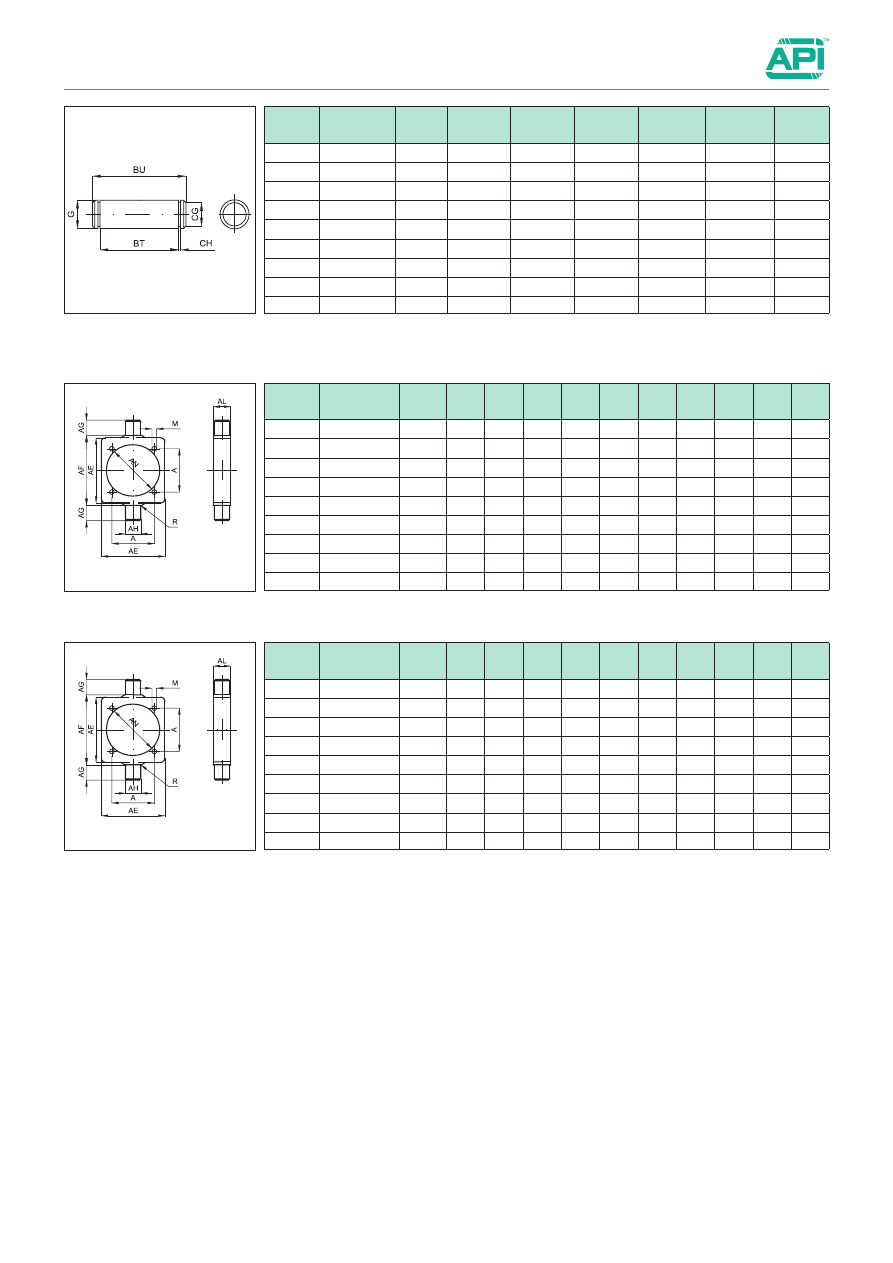
Mounting for CNOMO in steel

Type: 

CTN

Round center trunnion not adjustable 

(threaded)

Code

Item

For cyl. 

Ø mm

A

AE

AL

AH

AG

AF

AN

R

M

Weight 

(g)

040541

CTN032AQCN

32

33

46

15

12

12

50

37

1

M6

130

040542

CTN040AQCN

40

40

59

20

16

16

63

46

1,5

M6

306

040543

CTN050AQCN

50

49

69

20

16

16

73

56

1,6

M8

370

040544

CTN063AQCN

63

59

84

25

20

20

90

69

1,6

M8

702

040545

CTN080AQCN

80

75

102

25

20

20

108

87

1,6

M10

894

040546

CTN100AQCN

100

90

125

30

25

25

131

107

2

M10

1590

040547

CTN125AQCN

125

110

155

32

25

25

160

133,5

2

M12

2600

040548

CTN160AQCN

160

140

190

40

32

32

200

171

2,5

M16

4300

040549

CTN200AQCN

200

175

240

40

32

32

250

211

2,5

M16

7450

It is supplied with 2 seegers included.

Type: 

SEC

Pin for rear clevis

Code

Item

For cyl. 

Ø mm

G

BT

CG

CH

BU

Weight 

(g)

040221

SEC032AQCN

32

8

46

7,6

1,1

53

21

040222

SEC040AQCN

40

12

53

11,5

1,1

60

52

040223

SEC050AQCN

50

12

66

11,5

1,1

73

64

040224

SEC063AQCN

63

16

76

15,2

1,1

83

130

040225

SEC080AQCN

80

16

96

15,2

1,1

103

160

040226

SEC100AQCN

100

20

117

19

1,3

124

304

040227

SEC125AQCN

125

20

142

19

1,3

149

364

040228

SEC160AQCN

160

25

182

23,9

1,3

189

720

040229

SEC200AQCN

200

25

222

23,9

1,3

229

872

Type: 

CT

Round center trunnion adjustable

(with grains)

Code

Item

For cyl. 

Ø mm

A

AE

AL

AH

AG

AF

AN

R

M

Weight 

(g)

040559

CT032AQCN

32

33

46

15

12

12

50

37

1

M6

130

040558

CT040AQCN

40

40

59

20

16

16

63

46

1,5

M6

306

040538

CT050AQCN

50

49

69

20

16

16

73

56

1,6

M8

370

040540

CT063AQCN

63

59

84

25

20

20

90

69

1,6

M8

702

040545R

CT080AQCN

80

75

102

25

20

20

108

87

1,6

M10

894

040546R

CT100AQCN

100

90

125

30

25

25

131

107

2

M10

1590

040580

CT125AQCN

125

110

155

32

25

25

160

133,5

2

M12

2600

040630

CT160AQCN

160

140

190

40

32

32

200

171

2,5

M16

4300

040597

CT200AQCN

200

175

240

40

32

32

250

211

2,5

M16

7450

1

1.100.1

Mounting Accessories for Cylinders

Mountings for compact UNITOP in aluminium

Note:  The mounting screws are to be ordered separately. 

For screws see page 1.101.1.

Technical data

Material

Die-cast aluminium

Treatment

Sifting

Type: 

CM

Rear eye

Code

Item

For cyl. 

Ø mm

A

B

C

D

E

F

G

H

I

L

M

N

O

P

Q Weight 

(g)

040701 CM012/016ALUN 12-16 18 27 8,5 4,5 2,6

6

16

2

6

4,5

10

8

12

3

6

17

040702

CM020ALUN

20

22 34

11

5

2,6

6

20

2

8

5,5

12

10

16

3

8

21

040703

CM025ALUN

25

26 38

11

5

2,6

6

20

2

8

5,5

12

10

16

3

8

27

The pin is to be ordered separately: for the pin see page 1.98.2 (SEC..AQIS).

Type: 

CF

Rear clevis

Code

Item

For cyl. 

Ø mm

A

B

C

D

E

F

G

H

I

L

M

N

O

P

Q Weight 

(g)

040711

CF032ALUN

32

32 48 13,5 5,5 5,5

9

22

2,5

10

6,6

14

12

26

45 10

60

040712

CF040ALUN

40

42 58 13,5 5,5 5,5

9

25

2,5 12,5 6,6

14

14

28

52 12

104

040713

CF050ALUN

50

50 66 15,5 7,5 6,5 11

27

2,5 12,5

9

18

14

32

60 12

142

040714

CF063ALUN

63

62 83

18 7,5 6,5 11

32

4

15

9

18

18

40

70 16

240

040715

CF080ALUN

80

82 102 19

9

10 13

36

4

15

11

23

18

50

90 16

420

040716

CF100ALUN

100

103 123 19

9

10 15

41

4

20

11

28

23

60 110 20

721

Standard executions

Version

Sym.

Type

Rear eye

CM..ALUN

Rear clevis

CF..ALUN

Flange

FL..ALUN

Aluminium

1.100.2

Mounting Accessories for Cylinders

Mountings for compact UNITOP in aluminium

Type: 

FL

Flange Ø  12 ÷ 25 mm.

Code

Item

For cyl. 

Ø mm

A

B

C

D

E

F

G

H

I

L

M

Weight 

(g)

040721 FL012/016ALUN

12-16

18

43

55

18

29

4,5

9

5,5

10

5,4

10

34

040722

FL020ALUN

20

22

55

70

22

36

5,5

10

6,6

10

5,4

12

55

040723

FL025ALUN

25

26

60

76

26

40

5,5

10

6,6

10

5,4

12

68

For rear 90° hinge use:
- from bore 12 to 25 mm 

Rear clevis ISO 6432, type CF (see page 1.95.1).

- from bore 32 to 100 mm 

Rear 90° hinge VDMA, type ASV (see page 1.97.2).

Type: 

FL

Flange Ø  32 ÷ 100 mm.

Code

Item

For cyl. 

Ø mm

A

B

C

D

E

F

G

H

I

L

M

N

Weight 

(g)

040724

FL032ALUN

32

32

65

80

32

50

6,6

11

7

10

6,4

14

32

88

040725

FL040ALUN

40

42

82

102

42

60

6,6

11

9

10

6,4

14

36

143

040726

FL050ALUN

50

50

90

110

50

68

9

15

9

12

8,6

18

45

204

040727

FL063ALUN

63

62

110

130

62

87

9

15

9

15

8,6

18

50

411

040728

FL080ALUN

80

82

135

160

82

107

11

18

12

15

10,6

23

63

616

040729

FL100ALUN

100

103

163

190

103

128

11

18

14

15

10,6

28

75

890

1

1.100.50

Mounting Accessories for Cylinders

Mountings for compact UNITOP in steel

The pin is to be ordered separately: for the pin see page 1.98.2 (SEC..AQIS).

Note:  The mounting screws are to be ordered separately. 

For screws see page 1.101.1.

O

I

Type: 

CM

Rear eye

Type: 

CF

Rear clevis

Technical data

Type

Materials and treatments

Steel 

 A105

Fe 37

Black cat-

aphoresis

White 

zinking

CM..AQUN

CF..AQUN

FL..AQUN

PB..AQUN

Code

Item

For cyl. 

Ø mm

A

B

C

D

E

F

G

H

I

L

M

N

O

P

Q

R

S Weight 

(g)

040732

CM020AQUN

20

22 34 11

5

2,6 6

20

2

8 5,5 12 10 16

3

6

28

8

64

040733

CM025AQUN

25

26 38 11

5

2,6 6

20

2

8 5,5 12 10 16

3

6

28

8

80

Code

Item

For cyl. 

Ø mm

A

B

C

D

E

F G H

I

L M N O

P

Q

R

S

T

U Weight 

(g)

040741 CF032AQUN

32

32 48

-

11 5,5 9 22 2,5 10 6,6 14 12 26 45 1,3 1,5 32

8 10

178

040742 CF040AQUN

40

42 58

-

11 5,5 9 25 2,5 12,5 6,6 14 14 28 52 1,3 1,3 37,5 9 12

313

040743 CF050AQUN

50

50 66 15,5 7,5 6,5 11 27 2,5 12,5 9 18 14 32 60 1,5 1,5 39,5 8 12

431

040744 CF063AQUN

63

62 83

-

15 6,5 11 32 4

15

9 18 18 40 70 1,5 1,5 47 10,5 16

707

040745 CF080AQUN

80

82 102 19

9 10 13 36 4

15 11 23 18 50 90 1,5 1,5 51 10 16 1213

040746 CF100AQUN

100

103 123 19

9 10 15 41 4

20 11 28 23 60 110 1,5 1,5 61

9 20 2200

Standard executions

Version

Sym.

Type

Rear eye

CM..AQUN

Rear clevis

CF..AQUN

Flange

FL..AQUN

Low foot

PB..AQUN

Steel

1.100.51

Mounting Accessories for Cylinders

Mountings for compact UNITOP in steel

Type: 

FL

Flange Ø  12 ÷ 25 mm.

Type: 

FL

Flange Ø  32 ÷ 100 mm.

Type: 

PB

Low foot Ø  40 ÷ 100 mm.

Type: 

PB

Low foot Ø  12 ÷ 32 mm.

It is supplied singly.

It is supplied singly.

Code

Item

For cyl. 

Ø mm

A

B

C

D

E

F

G

H

I

L

M

Weight 

(g)

040751 FL012/016AQUN

12-16

18

43

55

18

29

4,5

9

5,5

10

5,4

10

10

040752

FL020AQUN

20

22

55

70

22

36

5,5

10

6,6

10

5,4

12

16

040753

FL025AQUN

25

26

60

76

26

40

5,5

10

6,6

10

5,4

12

20

Code

Item

For cyl. 

Ø mm

A

B

C

D

E

F

G

H

I

L

M

N

Weight 

(g)

040754

FL032AQUN

32

32

65

80

32

50

6,6

11

7

10

6,4

14

32

260

040755

FL040AQUN

40

42

82

102

42

60

6,6

11

9

10

6,4

14

36

420

040756

FL050AQUN

50

50

90

110

50

68

9

15

9

12

8,6

18

45

600

040757

FL063AQUN

63

62

110

130

62

87

9

15

9

15

8,6

18

50

1200

040758

FL080AQUN

80

82

135

160

82

107

11

18

12

15

10,6

23

63

1800

040759

FL100AQUN

100

103

163

190

103

128

11

18

14

15

10,6

28

75

2550

Code

Item

For cyl. 

Ø mm

C

B

D

E

F

G

H

I

S

T

R

U

Z

Weight 

(g)

040761 PB012/016AQUN

12-16

18

18

30 17,5 17,5 4,4 13 13

3

15

9

2

5,5

20

040762

PB20AQUN

20

22

22

36

22

22

5,4 16 16

4

17

10

2

6,6

32

040763

PB25AQUN

25

26

26

40

22

23

5,4 17 16

4

19

11

2

6,6

38

040764

PB32AQUN

32

32

32

50

26

24

6,6 16 18

5

20

12

2

6,6

66

Code

Item

For cyl. 

Ø mm

C

B

D

E

F

G

H

I

S

U

Z

Weight 

(g)

040765

PB040AQUN

40

42

42

60

28

29,5

6,6

21,5

20

5

5

9

100

040766

PB050AQUN

50

50

50

68

32

30

9

22

24

6

5

9

150

040767

PB063AQUN

63

62

62

84

39

39

9

28,5

27

6

5

11

250

040768

PB080AQUN

80

82

82

102

42

36,5

11

24,5

30

8

5

11

380

040769

PB100AQUN

100

103

103

123

45

38,5

11

26,5

33

8

5

13,5

500

1

1.101.1

Mounting Accessories for Cylinders

Mounting screws and nuts

VTCEI - UNI5931

VBTR - DIN6912

NUT - UNI5589

GROWER - DIN127B

MOUNTING SCREWS FOR CYLINDERS ISO 15552

Ø 

Cylind.

Code

Item

Normative

CF

CM

CFS

P

CMS

FL

FLV

PB

CFA

CTA

32

880179

VTCEIM6x16

UNI5931

040771

VTCEIM6x18

UNI5931

040782

VBTRM6x18

DIN6912

040691

VTCEIM6x20

UNI5931

40

880179

VTCEIM6x16

UNI5931

040771

VTCEIM6x18

UNI5931

040782

VBTRM6x18

DIN6912

040691

VTCEIM6x20

UNI5931

880174

VTCEIM6x25

UNI5931

50

881144

VTCEIM8x16

UNI5931

040772

VTCEIM8x20

UNI5931

040783

VBTRM8x20

DIN6912

040692

VTCEIM8x25

UNI5931

63

881144

VTCEIM8x16

UNI5931

040772

VTCEIM8x20

UNI5931

040783

VBTRM8x20

DIN6912

040692

VTCEIM8x25

UNI5931

880824

VTCEIM8x30

UNI5931

80

040773

VTCEIM10x20

UNI5931

040784

VBTRM10x20

DIN6912

881228

VTCEIM10x25

UNI5931

040693

VTCEIM10x30

UNI5931

100

040773

VTCEIM10x20

UNI5931

040784

VBTRM10x20

DIN6912

881228

VTCEIM10x25

UNI5931

040693

VTCEIM10x30

UNI5931

883537

VTCEIM10x35

UNI5931

125

040774

VTCEIM12x25

UNI5931

883538

VTCEIM12x30

UNI5931

883539

VBTRM12x30

DIN6912

040694

VTCEIM12x35

UNI5931

160

881914

VTCEIM16x25

UNI5931

040775

VTCEIM16x30

UNI5931

883540

VBTRM16x30

DIN6912

040695

VTCEIM16x40

UNI5931

200

881914

VTCEIM16x25

UNI5931

040775

VTCEIM16x30

UNI5931

883540

VBTRM16x30

DIN6912

040695

VTCEIM16x40

UNI5931

250

883541

VTCEIM20x25

UNI5931

883542

VTCEIM20x35

UNI5931

883543

VBTRM20x35

DIN6912

320

883544

VTCEIM24x40

UNI5931

883545

VBTRM24x40

DIN6912

Type: 

VTCEI

Type: 

VBTR

Type: 

NUT

Type: 

GROWER

1.101.2

Mounting Accessories for Cylinders

Mounting screws and nuts

MOUNTING NUTS AND GROWERS FOR CYLINDERS CNOMO

Ø 

Cylind.

Code 

(nut)

Item 
(nut)

Normative 

(nut)

Code 

(grower)

Item 

(grower)

Normative 

(grower)

CF

AN

P

PL

FL

PB

25/32 

40

041450

D6x1

UNI5589

880166

M6ZB

DIN127B

50/63

041451

D8x1,25

UNI5589

880066

M8ZB

DIN127B

80 

100

041453

D10x1,5

UNI5589

078384

M10ZB

DIN127B

125

041460

D12x1,75

UNI5589

880784

M12ZB

DIN127B

160 
200

880207

D16x2

UNI5589

078401

M16ZB

DIN127B

MOUNTING SCREWS FOR CYLINDERS ISO 21287

Ø 

Cylind.

Code

Item

Normative

CF

CM

CFS

P

CMS

FL

FLV

PB

CFA

CTA

20/25

880164

VTCEIM5x20

UNI5931

32/40

880174

VTCEIM6x25

UNI5931

VBTRM6x25

UNI6919

50/63

040692

VTCEIM8x25

UNI5931

880824

VTCEIM8x30

UNI5931

VBTRM8x30

UNI6919

80/100

040693

VTCEIM10x30

UNI5931

VBTRM10x30

UNI6919

MOUNTING SCREWS FOR CYLINDERS UNITOP

Ø 

Cylind.

Code

Item

Normative

CF

CM

FL

PB

12/16

880220

VTCEIM4x12

UNI5931

880842

VTCEIM4x16

UNI5931

20/25

880517

VTCEIM5x14

UNI5931

880164

VTCEIM5x20

UNI5931

32/40

880179

VTCEIM6x16

UNI5931

040771

VTCEIM6x18

UNI5931

50

881144

VTCEIM8x16

UNI5931

040772

VTCEIM8x20

UNI5931

63/80 

100

881228

VTCEIM10x25

UNI5931

ROD NUTS FOR CYLINDERS ISO 6432 - ISO 15552 -  ISO 21287

Ø 

Cylind.

Code

Item

Normative

8/10

881397

D4x0,7

UNI5589

12/16

041450

D6x1

UNI5589

20

041451

D8x1,25

UNI5589

25/32

041452

D10x1,25

UNI5589

40

041454

D12x1,25

UNI5589

50/63

041455

D16x1,5

UNI5589

80/100

041456

D20x1,5

UNI5589

125

041458

D27x2

UNI5589

160/200 041459

D36x2

UNI5589

250

041449

D42x2

UNI5589

320

-

D48x2

-

ROD NUTS FOR CYLINDERS CNOMO

Ø 

Cylind.

Code

Item

Normative

25/32

041453

D10x1,5

UNI5589

40/50

041455

D16x1,5

UNI5589

63/80

041456

D20x1,5

UNI5589

100/125 041458

D27x2

UNI5589

160/200 041459

D36x2

UNI5589

1

1.105.1

Mounting Accessories for Cylinders

Adjustable hydraulic shock absorbers

Series of adjustable hydraulic shock absorbers.
They absorb the impact energy on the rod by the displacement 
of oil from one chamber to another inside the body of the cush-
ioning.
This displacement is controlled by a valve and a throttling mech-
anism according to the adjustment brought in.
The adjustment is carried out by a nut set in the rear end.
The adjusting field is from 0 to 9 and the nut is provided with a 
stopper grub screw.
The optimal cushion is obtained:
1.   If the cushion is too high at the beginning of the stroke, move 

the nut towards 9.

2.   If the cushion is too high near the end of the stroke, move the 

nut towards 0.

For selection of shock absorbers see page 1.105.2.
In the version without mechanical stopper the cushioning must 
be provided with an external one (mechanical stopper) set at 0,5 
- 1 mm before the end of the stroke.

NUT

STROKE

KEYWAYS

WITH THREAD

Technical data

Temperature range

Type DR:    + 5 °C ÷ + 70°C 
Type DRF:    + 12 °C ÷ + 90°C

Materials

Body: 

Burnished steel 

Rod: 

Stainless steel

Spring: Steel
Seals: 

Nitrile rubber (NBR) - Polyurethane, Elastomer

Maximum impact velocity

4 m/s

Code

Item

Stroke

A

B

C

D

E

F

G

H

I

J

M CH Maximum absorbing 

capacity (Nm) 

Efficiency 

measurement

Weight 

(g)

Per cicle 

(W3)

Per hour 

(W4)

minimum 

(Kg.)

maximum 

(Kg.)

041801

DR1008

8

10x1 66,5 14,5 2,5 8,8

40

-

6

-

6,5 12

13

1,8

3600

0,2

10

26

041802

DR1210

10

12x1

84

18 3,5 10,8

60

-

8

-

8

6

14

4

6000

0,9

57

43

041803

DRF1412

12,5 14x1,5 87 17,5 8

12

61

12

12

12

10 8,5 17

17

35000

0,6

90

60

041804

DRF2019

19,1 20x1,5 117,9 30 4,8 16,8 74,7 12,7 16,8 18

11 13,2 24

25

45000

2,3

226

130

041805

DRF2525

25,4 25x1,5 142,6 36,3 6,3 22,4 89,7 12,7 22,9 23

11 16,6 30

88

68000

9

1360

310

041806

DRF2540

40

25x1,5 189 51,1 6,3 22,4 121,3 12,7 22,9 23

11 16,6 30

100

90000

14

2040

400

Standard executions

Version

Symbol

Type

Without mechanical 
stopper

DR

With mechanical stopper 
included

DRF

6)   Calculate the efficiency measurement:

ME = 

W

3

 • 

2

V

2

 (Kg)

Check that the value obtained is within the limits indicated 
for the chosen cushioning and this to get a linear and pro-
gressive cushion.
7)  

Were the “ME” out of the limits, you should choose a 
cushioning with a different capacity of efficiency meas-
urement. Varying the cushion length you can change the 
“ME”; however, at each variation of the cushion length 
you must remember to calculate the propelling energy of 
the point 3 again.

8)   Check whether the cushioning is condition to dissipate the 

energy generated by work frequency per hour into heat:

W

4

 =  W

3

 • X  (Nm/h)

9)   Were the cushioning not in condition to dissipate it, you 

should choose among:

    a)  Use of a cushioning with a higher capacity per hour 

taking care of calculating the point 3 again (were the 
cushion length different).


b)  

Use of a system with recirculation or external air/oil 
tank, both characterised by a higher capacity per hour

     c)  Cooling of the cushioning by air blow or another refrig-

erating fluid.

HOW TO CHOOSE

FACTORS

1.105.2

Mounting Accessories for Cylinders

Adjustable hydraulic shock absorbers

Symbol

W1 = Kinetic energy per cycle

(Nm)

W2 = Motive energy per cycle

(Nm)

W3 = Total energy per cycle

(Nm)

W4 = Total energy per hour 

(Nm/h)

F

= Motive power

(N)

x

= Number of cycles per hour

(1/h)

s

= Cushioning length

(m)

v

= Mass velocity 

(m/s)

m

= Cushioned mass

(Kg)

ME = Efficiency measurement

(Kg)

The shock absorbers are selected according to their energy 
absorbing capacity.
The capacity values identify both the mass that can be cush-
ioned and the energy that can be absorbed per cycle and 
hour. So the required performances must be compared with 
the table of the cushionings capacities to make sure that the 
energy can be absorbed, converted into heat and dissipated 
in the atmosphere.

Energy

 - The factors that must be considered at the moment 

of selection are:
-  

Kinetic energy (W1): it is the energy generated by the 
weight and the velocity of the mass that must be cushioned.

-   Motive energy (W2): it is the work, produced by the motive 

power acting on the mass that must be cushioned, multi-
plied by the cushion length.

-   Total energy per cycle (W3): it is the sum of the 2 preced-

ing values and is the energy that must be dissipated every 
cycle.

-  Total energy per hour (W4): it is the product of the total 

energy per cycle by the number of cycles per hour; so it is 
the energy the cushioning must dissipate every hour.

-   Efficiency measurement (ME): it is the mass (theoretical), 

which, without motive power and at the same velocity of 
the real mass, would have a kinetic energy equal to the 
total energy per cycle (W3) of the real application. 
It is not the mass that must be cushioned; it doesn’t indi-
cate the power supported by the cushioning.

The choice of the optimal cushioning can be easily made by 
the procedure shown here.
In any case our technicians are always at your disposal to 
help you to choose the fittest cushioning, to solve limit appli-
cations or study special solutions.
1)   Precisely determine the data of the problem, that is the 

calculus factors m, v, F, x, s shown above.

2)   Calculate the kinetic energy of the mass:
 

   W

1

 =0,5 . m . v

2

 (Nm).


Choose a cushioning with a capacity per cycle higher 
than the calculated value. The cushion length chosen 
must be used at point 3).

3)  If there is an external motive power (hydraulic or pneu-

matic cylinder, motor, gravity, etc.) calculate the work 
done:


   W

2

 = F · s (Nm).

4)  

Calculate the total energy that must be dissipated per 
cycle.


   W

3

 = W

1

 + W

2

 (Nm).

     Check that the value obtained is within the capacity limits 

of the chosen cushioning.


Otherwise you must consider a cushioning with higher 
cushion length or diameter and in case calculate W

2

 and 

W

3

 again.

     It can be necessary to compare cushionings with different 

cushion lengths and do the calculuses again each time.

5)   It is better to choose a cushioning with a capacity 25 per 

cent higher than the required one in order to:

     a) Let following possible increases of the impact energy.
     b)  Work with safe margins when velocities are not easily 

valuable.


c)  

Make sure that the cushioning lasts long, especially 
when working in dusty or contaminated environments.

1

1.110.1

Switches and Brackets

Magnetic switches ASV

The magnetic reed switches are magnetic sensors responding to 
the presence of a magnetic field.
When mounted on a cylinder tube they detect the presence of 
the magnetic field generated by the magnet set on the piston and 
so of the piston itself.
This information is used to signal electrical circuits as required.

The sensor ASV can be applied directly to the hollows of the 
cylinder tube from above.

For cables with M8 connector 

see page 1.110.3

For fixing brackets 

see page 1.120.1

For coupling item / switches 


see pag.


1.120.5

SENSING POINT

1 = Brown (+)

4 = Black (out)

3 = Blue (-)

For 

ATEX 

switches see

page 1.110.10

Technical data

Item

ASV1C...

ASV4D...

ASV7N2M8

ASV7M2M8

ASV1H525

Circuit

Reed, 2 poles

Reed, PNP, 3 

poles

Reed-Hall, PNP, 3 

poles

Reed-Hall, NPN, 3 

poles

Reed, 2 poles

Switching

Normally open

Normally open, solid state output

Normally closed

Voltage

5 ÷ 240 V DC/AC

10 ÷ 30 V DC

5 ÷ 120 V DC/AC

Switching current

100 mA max

Contact rating

10 W

3 W max

10 W

Voltage drop

3 V max

0,1 V max

2 V max

3,5 V max

LED

Red

Yellow

Yellow

Red

Yellow

Cable

Ø 3,3 PU

Ø 3 PUR

Temperature range

-10 °C ÷ +70 °C

Protection class

IEC 529  IP67

Standard executions

Version

Circuit

Code

Item

Reed, 2 poles, 
with flying lead 
flexible cable 
2,5 mt.

~

~+

POWER

LOAD

BRN

BLU

070946

ASV1C525

Reed, 2 poles, 
with flying lead 
flexible cable  
5 mt.

~

~+

POWER

LOAD

BRN

BLU

071863

ASV1C550

Reed, 2 poles, 
with flying lead 
flexible cable 
10 mt.

~

~+

POWER

LOAD

BRN

BLU

071864

ASV1C51K

Reed, 2 poles, 
with M8 
connector

~

~+

POWER

LOAD

BRN

BLU

071189

ASV1C5M8

Reed PNP, 3 
poles, with flying 
lead flexible 
cable 2,5 mt.

+

LOAD

BRN

BLU

BLK

POWER

073639

ASV4D225

Reed PNP, 3 
poles, with M8 
connector

+

LOAD

BRN

BLU

BLK

POWER

070246

ASV4D2M8

Reed-Hall PNP, 3 
poles, with M8 
connector

+

LOAD

POWER

MAIN

CIRCUIT

BRN

BLU

BLK

070247

ASV7N2M8

Reed-Hall NPN, 
3 poles, with M8 
connector

+

LOAD

POWER

MAIN

CIRCUIT

BRN

BLU

BLK

070372 ASV7M2M8

Reed, NC, 
2 poles, with flying 
lead flexible cable 
2,5 mt.

~

~+

POWER

R

L

BRN

BLU

072918

ASV1H525

1.110.2

Switches and Brackets

Magnetic switches ASC

The magnetic reed switches are magnetic sensors responding to 
the presence of a magnetic field.
When mounted on a cylinder tube they detect the presence of 
the magnetic field generated by the magnet set on the piston and 
so of the piston itself.
This information is used to signal electrical circuits as required.

The sensor ASC can be applied directly to the grooves of the 
cylinder tube without further brackets.

For cables with M8 connector 

see page 1.110.3

For fixing brackets 

see page 1.120.1

For coupling item / switches 

     see pag.


1.120.5

4.6

SENSING POINT

4

2,8

1 = Brown (+)

4 = Black (Out)

3 = Blue (-)

(ASC7)

10 

(ASC1)

Technical data

Circuit

Reed, 2 poles

Reed-Hall, PNP, 3 poles

Reed-Hall, NPN, 3 poles

Switching

Normally open - SPST

Normally open, solid state output

Voltage

5 ÷ 120 V DC/AC

5 ÷ 28 V DC

Switching current

100 mA max

Contact rating

6 W max

3 W max

Voltage drop

3.5 V max

0,5 V max (50 mA)

LED

Red

Green

Red

Cable

Ø 2,8 Grey

Ø 2,8 Black

Temperature range

-10 °C ÷ +70 °C

Protection class

IEC 529  IP67

Electrical protection

-

Reverse polarity -Sourge suppression

Standard executions

Version

Circuit

Code

Item

Reed, 2 poles, 
with flying lead 
flexible cable 
2,5 mt.

~

~+

POWER

LOAD

BRN

BLU

070248

ASC1C525

Reed-Hall PNP, 
3 poles, with 
M8 
connector

LOAD

POWER

BRN

BLU

BLK

+

MAIN

CIRCUIT

070249

ASC7N2M8

Reed-Hall NPN, 
3 poles, with 
M8 
connector

LOAD

POWER

BRN

BLU

BLK

+

MAIN

CIRCUIT

070382

ASC7M2M8

1

1.110.3

Switches and Brackets

Cables with M8 connector

1 = Brown

4 = Black

3 = Blue

Technical data

Material of the cable

PVC black

Material of the connector

Body: Polypropylene

Contacts: 

Gilded brass

Nut: 

Nickel plated brass

Cable data

3 x 24 AWG / 0,22 mm

2

 flexble, spatter resistant, oil resistant, insulation 300 V

Temperature range

- 20 °C ÷ + 80 °C

Protection

IP 67

Standard executions

Version

Code

Item

Cable mt. 2 with 
M8 connector

070269

CAV20M8

Cable mt. 5 with 
M8 connector

070250

CAV50M8

Cable mt. 10 with 
M8 connector

070298

CAV1KM8

1.110.10

Switches ATEX

Directive 2014/34/EU

Technical data

Item

MK500A

MK502A

Electrical design

DC PNP

Connection to certified intrinsically safe circuits with 

the max. values 

U = 15 V / I = 50 mA / P = 120 mW

Operating voltage 

10 ÷ 30 V DC

8,2 V DC

Current consumption 

10 mA

≥ 2,2 mA

Protection class 

III

III

Reverse polarity protection 

SI

-

Power-on delay time 

< 30 ms

-

Output function

NO

NO

Voltage drop 

< 2,5 V

-

Current rating 

100 mA

-

Short-circuit protection 

SI

-

Overload protection 

SI

-

Switching frequency 

10000 Hz

2000 Hz

Magnetic sensitivity 

2,8 mT

2 mT

Travel speed 

> 10 m/s

> 10 m/s

Hysteresis

< 1,5 mm

< 1 mm

Repeatability

< 0,2 mm

< 0,2 mm

Temperature

-25 °C ÷ +60 °C

-25 °C ÷ +70 °C

Protection 

IP 65 / IP 67

IP 65 / IP 67

ATEX certification

  II 3D Ex tc IIIC T125°C Dc X

  II 1G Ex ia IIC T4 Ga

  II 1D Ex ia IIIC T135°C Da

Materials

PA - stainless steel

PA - stainless steel

LED

Yellow

Yellow

Cable

PVC / 2m; 3x0.14mm

2

PVC / 6m; 2x0.14mm

2

Weight

59 g

86 g

Series of magnetic switches conforming to 
2014/34/EU Directive - ATEX

For fixing brackets 

see page 1.120.1

For coupling item / switches                see pag.


1.120.5

Standard executions

Version

Circuit

ATEX

Code

Item

3 poles,
with flying lead 
flexible cable 
2 m.

BN
BK
BU

II3D

 071120

MK500A

2 poles,
with flying lead 
flexible cable 
6 m.

BN

BU

II1G

071108

MK502A

BN: brown
BK: black
BU: blue

5,

1

5

6,

5

5,7

6,2

25,3

LED

BN
BK
BU

BN

BU

MK500A

MK502A

1

1.110.20

Switches and Brackets

Magnetic switches ASH, for high temperatures

The magnetic reed switches are magnetic sensors responding to 
the presence of a magnetic field.
These sensors are specifically designed for high temperatures.
When mounted on a cylinder tube they detect the presence of 
the magnetic field generated by the magnet set on the piston and 
so of the piston itself.
This information is used to signal electrical circuits as required.
The sensor ASH can be applied only using a specific bracket.

For fixing brackets 

see page 1.120.1

For coupling item / switches 


see pag.


1.120.5

13

11

12

30

For 

ATEX 

switches see

page 1.110.10

Technical data

Item

ASH6C550

Circuit

Reed, 2 poles

Switching

Normally open

Voltage

5 ÷ 240 V DC/AC

Switching current

500 mA max

Contact rating

10 W

Voltage drop

0,5 V max

Cable

Ø 3, 2C, Teflon

Temperature range

-10 °C ÷ +140°C

Protection class

IEC 60529 IP67

Standard executions

Version

Circuit

Code

Item

Reed, 2 poles, 
with flying lead 
flexible cable  
5 mt.

~

~+

POWER

LOAD

BRN

BLU

074047

ASH6C550

Sensing point

1

Switches and Brackets

Brackets for magnetic switches

Series of brackets used to fix the different types of magnetic reed 
switches for the different types of existing cylinders.
For the coupling / item table see page 1.120.5

1.120.1

Standard executions

Version

Code

Item

Locking band for cylinder 
ISO 6432 Ø 8 mm

072901

AFM8

Locking band for cylinder 
ISO 6432 Ø 10 mm

072902

AFM10

Locking band for cylinder 
ISO 6432 Ø 12 mm

072903

AFM12

Locking band for cylinder 
ISO 6432 Ø 16 mm

072904

AFM16

Locking band for cylinder 
ISO 6432 Ø 20 mm

072905

AFM20

Locking band for cylinder 
ISO 6432 Ø 25 mm

072906

AFM25

Locking band for round 
cylinders 10 ÷ 63 mm

072907

AFR1063

Bracket for AMA cylinders 
Ø 32 and 40 mm

072908

AS101

Bracket for AMA cylinders 
Ø 50 and 63 mm

072909

AS102

Bracket for AMA cylinders 
Ø 80 and 100 mm

072910

AS103

Bracket for AMA cylinders 
Ø 125 mm

072911

AS104

Bracket for tie rod cylinders 
Ø 32 and 40 mm

072912

AS105

Bracket for tie rod cylinders 
Ø 50 

÷

 100 mm

072913

AS106

Bracket for tie rod cylinders 
Ø 125 mm

072909

AS102

Bracket for cylinders 
Ø 160 and 200 mm

072910

AS103

Bracket for tie rod cylinders 
Ø 250 and 320 mm

072917

AS110

Bracket for short stroke 
cylinders

072915

AS108

Bracket for rodless cylinders

072916

AS109

Locking bands for cylinders ISO 6432

Material: Polyamide

Mounting screw included in the Kit

Code

Item

A

B

C

Ø D

E

F

072901

AFM8

21,4

18,9

6,45

9,3

18

9

072902

AFM10

23,4

20,9

7,45

11,3

18

9

072903

AFM12

25,4

22,9

8,45

13,3

18

9

072904

AFM16

29,4

26,9

10,45

17,3

18

9

072905

AFM20

33,4

30,9

12,45

21,3

18

9

072906

AFM25

38,4

35,9

14,95

26,3

18

9

1.120.2

Switches and Brackets

Brackets for magnetic switches

Code

Item

072907

AFR1063

6.5

8

10

3.3

5.6

Locking bands for round cylinders Ø 10-63

Metal bracket, screw and adaptor included in the Kit

10.5

18

6.9

2

13.5

12

15°

Brackets for short stroke cylinders

Material: Polyamide

Code

Item

072915

AS108

12.5

18

6.95

2.2

12.9

10.1

65°

Brackets for rodless cylinders

Material: Polyamide

Code

Item

072916

AS109

Brackets for cylinders ISO 15552

Material: Aluminium

Mounting screw included in the Kit

3,4

5,4

6,7

Code

Item

A

B

072908

AS101

11,5

11

072909

AS102

14,5

14

072910

AS103

16,5

20

072911

AS104

17,5

24

072912

AS105

7

8

072913

AS106

10

14

072917

AS110

24,5

21

Brackets for ISO and CNOMO cylinders (only for ASH type switches)

Material: Aluminium

Mounting screw included in the Kit

Code

Item

A

B

077838

AS112

10,9

10,4

077651

AS113

14,1

13,5

074055

AS114

15,4

15

077839

AS115

16,3

16

B

A


Content      ..     11      12      13      14     ..