Api Pneumatic. GENERAL CATALOG (2019) - page 14
 

  Index      Manuals     Api Pneumatic. GENERAL CATALOG (2019)


Search            copyright infringement  


Content      ..     12      13      14      15     ..


Api Pneumatic. GENERAL CATALOG (2019) - page 14


1

Switches and Brackets

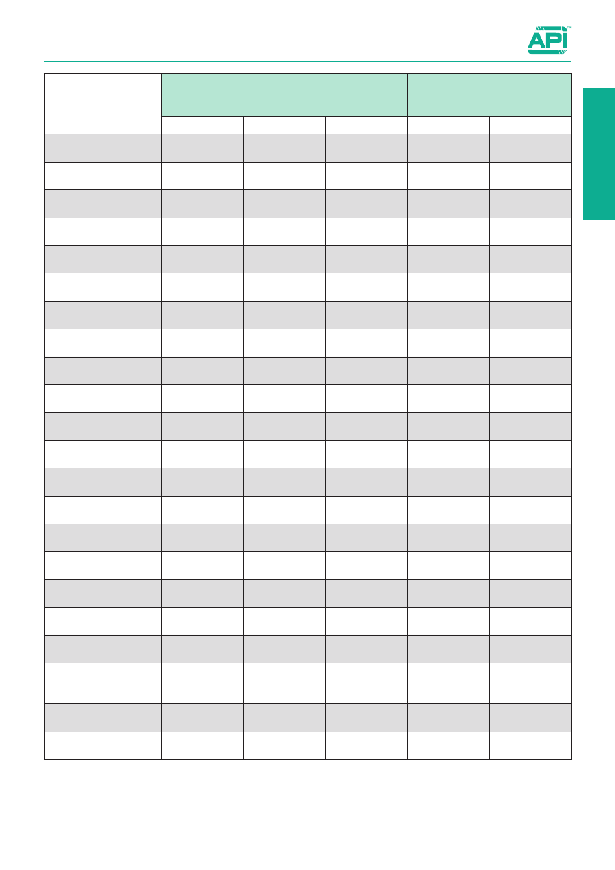
Table of coupling item / reed switches

1.120.5

▲ 

Direct mounting 


Mounting with braket


Not applicable

Item

STANDARD switches

ATEX switches

ASV

ASC

ASH

MK500A

MK502A

MSM

MDM-MDMA

AMA - BMA

AMT - BMT

REDM - RDM - RDMA

CM-CX

CIS-CI-CIN

CS-CD-CDN

DUM - DUMN

BSM

BDM - BDMN

GEDB - GEDS

GPB - GPS

GSB - GSS

S1-S2-S S4-S5-S6

CRTH - CRTHD 

CRTF

ARTMC - ARTMFC

ARTMLC - ARTMFLC

ARC - ARP

PAB - PAC - PPB
PPC - PPD - PPE

MDMX - MDMAX

AMX

RXDVA - RXDVD - RXDFP

RXDCM - RXDCS -  RXDCF

RXDBA - RXDBP 

RDMX - RDMAX

CIXS - CIX - CIXN

2

Valves

2

2.0

0

1

2

4

5

6

7

8

0

1

2

3

4

5

6

7

8

9

10

11

12

13

14

15

16

17

18

19

mm

in

mm

Valves

Technical data:

from page 2.1.1

15 mm directly operated 
solenoid valves

22 mm directly operated 
solenoid valves 

from page 2.2.1

from page 2.90.1

Manually operated valves 1/8”

from page 2.230.1

Manually operated valves 1/4”

from page 2.236.1

Ball valves

from page 2.310.1

Quick exhaust valves

from page 2.360.1

Uni-directional, safety and 
piloted stop valves

from page 2.370.1

from page 2.3.1

from page 2.50.1

Electrically and pneumatically
operated valves 1/8” - 1/4”

Electrically and pneumatically
operated valves 1/2”

Electrically and pneumatically
operated NAMUR valves 1/4”

from page 2.88.1

from page 2.88.20

Ball valves with actuators

from page 2.431.1

Limit switch box

from page 2.431.30

Handweel manipulator

from page 2.432.1

Electrically and pneumatically
operated valves ISO 2

from page 2.130.1

Indirectly operated solenoid 
valves for water and steam

from page 2.165.1

Electrically and pneumatically
operated valves ISO 1

from page 2.110.1

Coils and connectors

from page 2.200.10

Electrically operated valves 
with multiple connector

from page 2.105.1

NAMUR solenoid valves 

New

Microvalves Ø 4 and manual 
operating devices

from page 2.255.1

Mechanically operated 
valves Ø 4

from page 2.270.1

Mechanically operated valves
1/8”

from page 2.275.1

Integrated circuits

from page 2.170.1

Foot valves

from page 2.250.10

Slide valves

from page 2.300.1

Actuators

from page 2.430.1

2.1.1

Valves

Technical data

The following formula constitutes the relationship between all the aforementioned elements:

Q = 28,3 Kv 


D

p (p1 - 

D

p)

 where

=  flow [nl/min]

Kv 

=  valvular coefficient of the H2O valve [nl/min]

D

=  p1 - p2 = fall in pressure between upstream and downstream [ bar ]

p1 

=  absolute pressure upstream [ bar ] 

28,3  =  conversion coefficient from water to air

So: the capacities calculated with the given formula differ little from those that can be obtained from the flow characteristic of the 
corresponding valve.
Furthermore, it also provides confirmation, from the characteristic itself, of the limits of validity of the formula.
It is only valid for 

D

p < 

Ω

 p1; i.e. only up until the fall of pressure across the valve reaches a value equivalent to half the absolute 

supply pressure.

In this condition the air reaches max. velocity (critical velocity 

Vc

) and consequently maximum capacity 

Qmax

.

For 

D

p < 

Ω

 p1, the pressure energy is converted into kinetic energy with an increase in velocity and consequently capacity. For 

D

p < 

Ω

 p1, the extra pressure energy is no longer converted into velocity energy, but dissipated in local turbulences in the form 

of heat.

All of this is confirmed by the flow characteristics.
From the same characteristics it is possible to discover that that the value of the flow with 

D

p = 1 bar is 

@

 2/3 Qmax.

The capacity corresponding to 

D

p = 1 bar is defined 

“NOMINAL FLOW Qn”.

In the case of a valve, a different flow characteristic exists for each absolute supply pressure, and thus corresponding values for 
Qmax. and Qn.
Falls in pressure of 

D

p > 1 bar are too economically onerous, and for this reason it is advisable to limit the falls in pressure to 

D

= 0,5 bar, by choosing a larger size valve.

In the catalogue reference is normally made to the nominal flow, but the flow characteristics and the valvular coefficient are also 
provided.
Let’s calculate, for example, the flow of a valve with Kv = 12 NL/min, P

1

 = 6 bar,

D

P = 0,5 bar 

=  28,3*12 

 0,5 (7-0,5) = 612 [Nl/min]


Qn 

=  831 [Nl/min]


Q max  =  1118 [Nl/min]

Flow

(Nl/min.)

0

1

2

3

4

5

6

7

8   

700

600

500

400

300

200

100

0

Pressure (bar)

Flow of the valves:

The quantity of compressed air that can flow through the 
valve depends on the size of the orifices and the type 
of course that must be followed within the valve itself by 
the fluid under pressure. The flow of a valve is measured 
using suitable measuring circuits with the hypothesis that the 
upstream pressure is constant and that quantity of air required 
downstream is variable.

Curves known as “

FLOW CHARACTERISTICS

” are drawn, 

which indicate how the flow of the valve varies with the varia-
tion in downstream pressure, with a constant pressure supply. 

Once these characteristics are known, the flow of the valve 
is also known in all working conditions.

These curves show how the study model adopted for a valve 
- which consists of comparing it with a converging nozzle that 
releases a compressible gas with constant upstream pressure 
- is reasonably valid. Indeed, according to this model, the flow 
that passes through the nozzle depends on the following fac-
tors: the upstream pressure, the difference in pressure 

D

p

 and 

the valvular coefficient 

Kv.

The coefficient 

Kv

 summarizes the characteristics of the inter-

nal passages of the valve and is represented by the 

“number 

of litres of water that flow through the valve in one minute, 
in normal conditions (atmospheric pressure, 20 °C) in the 
presence of a fall in pressure 

D

p [AS1]= 1 bar.

2

Standard executions

Version

Symbol

Code

Item

3/2, N. C. 
12 V DC

034601 AE05C01200

3/2, N. C. 
24 V DC

034602 AE05C02400

3/2, N. C. 
24 V AC

034603 AE05C02450

3/2, N. C. 
110 V AC

034604 AE05C11050

3/2, N. C. 
230 V AC

034605 AE05C22050

3/2, N. A. 
12 V DC

034611 AE05A01200

3/2, N. A. 
24 V DC

034612 AE05A02400

3/2, N. A. 
24 V AC

034613 AE05A02450

3/2, N. A. 
110V AC

034614 AE05A11050

3/2, N. A. 
230 V AC

034615 AE05A22050

15 mm directly operated solenoid valves

3/2, normally open and normally closed

2.2.1

Series of directly operated poppet valves for single or manifold 
sub-bases, standard with coil and without connector.
The single base is M5 threaded.
The manifold bases can be supplied with M5 ports or with inte-
gral 4 mm push-in fitting.
For sub-bases 

see page 2.2.2.

For the connectors type A19207.. 

see page 2.210.10.

Note:  The maximum couple of locking of M3 screws must not 

exceed 0,5 Nm.


(The locking screws are included together with the valve).

Technical data

Fluid

Compressed filtered air with or without lubrication

Pressure range

0 ÷ 10 bar

Temperature range

-10 °C ÷ + 50°C

Orifice

1,1 mm.

Normal flow at 6 bar

35 Nl/min

Manual override

Two stable position, flat

Response time

5 ms (ON) - 6 ms (OFF)

Mounting

In any position

Duty cycle

ED 100%

Voltage tolerance

± 10%

Class protection

IP 65 (with connector already mounted)

Electrical consumption

2 W

Materials

Body: 

Acetal resin

Internal parts: 

Acetal resin - stainless steel

Seals: 

Nitrile rubber (NBR)

Screws: 

Zinc plated steel

15 mm directly operated solenoid valves

3/2, normally open and normally closed

2.2.2

M3

20,5

(R)

8

7

17

4

24

42

9,4

4,75

M3

15

3
2
1

3/2 N.C.
3/2 N.O.

1

2

3

IN

OUT EXH

9,7

4,0

3,8

5,4

M3

3x ø2 max.

BASE

9,4

ø 2

ø 2,5

4,05

3,8

ø 2

8,4

5,45

NAMUR

M3

20,5

(R)

8

7

17

4

24

42

9,4

4,75

M3

15

3
2
1

3/2 N.C.
3/2 N.O.

1

2

3

IN

OUT EXH

9,7

4,0

3,8

5,4

M3

3x ø2 max.

BASE

9,4

ø 2

ø 2,5

4,05

3,8

ø 2

8,4

5,45

NAMUR

M3

20,5

(R)

8

7

17

4

24

42

9,4

4,75

M3

15

3
2
1

3/2 N.C.
3/2 N.O.

1

2

3

IN

OUT EXH

9,7

4,0

3,8

5,4

M3

3x ø2 max.

BASE

9,4

ø 2

ø 2,5

4,05

3,8

ø 2

8,4

5,45

NAMUR

M3

20,5

(R)

8

7

17

4

24

42

9,4

4,75

M3

15

3
2
1

3/2 N.C.
3/2 N.O.

1

2

3

IN

OUT EXH

9,7

4,0

3,8

5,4

M3

3x ø2 max.

BASE

9,4

ø 2

ø 2,5

4,05

3,8

ø 2

8,4

5,45

NAMUR

Type: 

AE05...

3,5

2

1

ø 6

ø 3,25

M5

25

3,5

3

3,5

3,5

9

15

Single base

Type: 

ABAS05S

15

9,7

15

15

3

Type: 

ABAS05T

Closing plate

Manifold base

Type: 

ABAS05...

With M5 ports

Code

Item

Positions

A

B

034625

ABAS050205

2

44

37

034626

ABAS050305

3

60

53

034627

ABAS050405

4

76

69

034628

ABAS050505

5

92

85

034629

ABAS050605

6

108

101

034630

ABAS050705

7

124

117

034631

ABAS050805

8

140

133

034632

ABAS050905

9

156

149

034633

ABAS051005

10

172

165

Code

Item

034621

ABAS05S

Code

Item

034622

ABAS05T

2

22 mm directly operated solenoid valves

3/2, normally closed

Series of directly operated poppet valves for panel mounting. 
Base set up for single or modular installation.

Coils and connectors have to be ordered separately.
For the coils type ASA12... 

see page 2.200.1 

For the connectors type A122... 

see page 2.210.20

Code key

2.3.1

Standard executions 

Version

Symbol

Code

Item

3/2 N.C, with 
manual override 
solenoid/spring

12

2

3 1

034188 A1EM13012M

3/2 N.C, with 
manual override 
bistable

12

2

3 1

034189 A1EM13012B

Options

Suffix

Low temperature seals 

-25 ÷ +60°C

BT

Seals FKM

-10 ÷ +150°C

V

Series

Actuation

Size

Function

Orifice

Manual override

A1

EM = electrical
         modular

1 = 1/8” 30 = 3/2 NC 12 = Ø1.2 M = spring return 

B = bistable

Technical data

Fluid

Compressed filtered air, min. 5µm, with or without lubrication.

Pressure range

0 ÷ 10 bar

Temperature range

-10°C ÷ +60°C (standard)

-25°C ÷ +60°C (BT)

-10°C ÷ +150°C (V)

Orifice

1,2 mm

Flow

29 Nl/min at 6 bar at ∆P 1 bar

Weight

100 g

Mounting

In any position

Manual override

Spring return (M) - Bistable (B)

Materials

Base: 

Zinc alloy die cast

Tube: Brass

Cores: 

Steel AISI specific

Springs: Steel

Manual override: 

Nickel-plated brass

Locking nut: 

Plastic

Screws: 

Zinc plated steel

2.3.2

22 mm directly operated solenoid valves

3/2, normally closed

Manual override:
SPRING RETURN

Manual override:
BISTABLE

Version

Symbol

Code

Item

3/2 N.C, with 
manual override 
solenoid/spring

12

2

3 1

034188 A1EM13012M

3/2 N.C, with 
manual override 
solenoid/solenoid

12

2

3 1

034189 A1EM13012B

2

22 mm. directly operated solenoid valves

1/8” and 1/4”, 3/2, normally closed, electrically operated

Series of direct operated valves for mounting on the application (on 
cylinder or on rotary actuator, as shown in the examples at page 
2.10.4).

For versions conforming to ATEX 2014/34/UE Directive, 
classification Ex nA... 


see page 2.10.3

For further ATEX classifications ask to our sales departement.

Standard coils and connectors have to be ordered separately:
For the coils typer ASA12... 

vedi pag. 2.200.1

For connectors type A122...  

vedi pag. 2.210.20

2.10.1

Standard executions

Version

Symbol

Code

Item

1/8”, 3/2 N.C., with 
bistable manual 
override

12

2

3 1

034226

A1E130MD

1/4”, 3/2 N.C., with 
bistable manual 
override

034227

A1E230MD

1/8”, 3/2 N.C., with 
bistable manual 
override Ex nA

For code key see

table below

1/4”, 3/2 N.C, with 
bistable manual 
override Ex nA

Options

Suffix

Low temperature seals

(-25 ÷ +60°C)

BT

Seals FKM

 (-10°C ÷ +150°C)

V

Technical data

Fluid

Compressed filtered air, min. 5µm, with or without lubrication.

Pressure range

0 ÷ 10 bar

Temperature range

-10°C ÷ +60°C (standard)

-25°C ÷ +60°C (BT)

-10°C ÷ +150°C (V)

Orifice

1,2 mm.

Flow

29 Nl/min. at 6 bar ∆P 1 bar

Weight

100 g.

Mounting

In any position

Materials

Base

Zinc alloy die cast

Tube

Brass

Cores

Steel AISI specific

Springs

Spring steel

Manual override

Nickel-plated brass

Locking nut

Plastic

Screws

Zinc plated steel

Code key for

 standard versions

Series 

Actuation

Size

Function

Mounting

Options

A1

E = electrical

1 = 1/8”
2 = 1/4”

30 = 3/2 NC

MD = direct

BT = low temp.
        seals
 V  = FKM seals

Code key for ATEX 

versions

Series 

Actuation

Size

Function

Mounting

Hazardous areas

Voltages

Options

A1

E = electrical

1 = 1/8”
2 = 1/4”

30 = 3/2 NC

MD = direct

XX = II 3G Ex nA IIC T5 Gc X


II 3D Ex tc IIIC T95°C Dc X

B = 12 VDC
C = 24 VDC *


= 24 VAC*


I = 110 VAC *

O = 220 VAC *

BT = low temp.
        seals
 V  = FKM seals

* = Standard voltages

On request, they can be supplied 

according to 2014/34/EU - 

ATEX

II 2Gc IIB T5
II 2Dc T100°C

2.10.2

22 mm. directly operated solenoid valves

1/8” and 1/4”, 3/2, normally closed, electrically operated

Version

Symbol

Code

Item

1/8”, 3/2 N.C., with 
bistable manual 
override

034226

A1E130MD

Version

Symbol

Code

Item

1/4”, 3/2 N.C., with 
bistable manual 
override

034227

A1E230MD

12

2

3 1

12

2

3 1

2

2.10.3

22 mm. directly operated solenoid valves - Non-sparking coil Ex nA

1/8” and 1/4”, 3/2, normally closed, electrically operated Ex nA

Version

Symbol

Code

Item

1/8”, 3/2 N.C., with 
bistable manual 
override

A1E130MDXX..

Version

Symbol

Code

Item

1/4”, 3/2 N.C., with 
bistable manual 
override

A1E230MDXX..

II 3G Ex nA IIC T5 Gc X
II 3D Ex tc IIIC T95°C Dc X

II 3G Ex nA IIC T5 Gc X
II 3D Ex tc IIIC T95°C Dc X

12

2

3 1

12

2

3 1

2.10.4

Example: 

Mounting on micro-cylinder

12

2

3 1

Example of application of the direct control solenoid valve 
22 mm. series A1EMD on a single-acting microcylinder 
series MSM.
The valves of this series can be directly mounted on the 
cylinder’s connection without the use of intermediate pipes.

Example: 

Mounting on rotary actuator

12

2

3 1

Example of application of the direct control solenoid valve 
22 mm. series A1EMD on a single-acting rotary actuator 
series AR..SE.
The valves of this series can be directly mounted on the 
actuator connection without the use of intermediate pipes 
or plates.

22 mm. directly operated solenoid valves

1/8” and 1/4”, 3/2, normally closed, electrically operated

2

2.50.1

Valves series A1 

1/8”, 3/2, electrically operated

Series of spool valves, with static seals, high flow, for panel or 
sub-base mounting.
Coils and connectors have to be ordered separately.
For the coils type ASA12... 

see page 2.200.1 

For the connectors type A122... 

see page 2.210.20

For the sub-bases type A1B1... 

see page 2.65.1

Standard executions

Version

Symbol

Code

Item

3/2 NC

2

1

3

12

10

034003

A1E130

3/2 NO

2

1 3

23

12

034004

A1E131

3/2 

solenoid/solenoid

2

1

3

12

10

034005

A1E132

3/2 NC 

external air pilot

2

3

1

12

10

034006

A1K130

3/2 

solenoid/solenoid

external air pilot

2

1

3

12

10

034007

A1K132

Series

Actuation

Size

Function

Options

A1

E = electrical

K =  electrical with 

external air pilot

1


=


1/8”

30 = 3/2 NC

31 = 3/2 NO

32 =  3/2 sol./sol.

BT = low temp.

        seals

Code key

On request, they can be supplied 

according to 2014/34/EU - 

ATEX

II 2Gc IIB T5
II 2Dc T100°C

Technical data

Fluid

Compressed filtered air with or without lubrication. Lubrication, if started, must be continued.

Pressure range

Spring return: 1,5 ÷ 10 bar

Bistable: 1 ÷ 10 bar

Temperature range

-10°C ÷ +60°C (standard)

-25°C ÷ +60°C (BT)

Orifice

6,5 mm

Flow

650 Nl/min a 6 bar con ∆P 1 bar

Minimum external air pressure

1,5 bar

Mounting

In any position

Manual override

Bistable

Response time (at 6 bar)

solenoid/spring

solenoid/solenoid

Energising: 35 ms

De-energising: 15 ms

Energising: 20 ms

De-energising: 20 ms

Materials

Body: 

Anodised aluminium

Covers: 

Hostaform C 13031

Spool: 

Hard aluminium anodized

Distancers: 

Ixef 1022

Seals: 

Hydrogenated Nitrile Butadiene Rubber (HNBR)

Options

Suffix

Low temperature seals

(-25 ÷ +60°C)

BT

2.50.2

Valves series A1 

1/8”, 3/2, electrically operated

23.1

3.2

G1/8

22

17.2

15.5

4.2

32

108.5

15

12

5.8

14

10

G1/8

15.5

31.5

18

16

34

M5

Version

Symbol

Code

Item

3/2 NC

2

1

3

12

10

034003

A1E130

3/2 NO

2

1 3

23

12

034004

A1E131

G1/8

G1/8

17.2

10

161.5

16

M5

32

34

15

22

23.1

34

16

3.2

15.5

31.5

15

G1/8

4.2

15.5

5.8

18

14

Version

Symbol

Code

Item

3/2 

solenoid/solenoid

2

1

3

12

10

034005

A1E132

2

2.50.3

Valves series A1 

1/8”, 3/2, electrically operated

G1/8

G1/8

18

M5

G1/8

3.2

17.2

15.5

28.5

23.1

15.5

5.8

4.2

22

32

117.5

15

14

31.5

12

10

9

16

34

M5

G1/8

G1/8

18

72.5

17.2

15.5

G1/8

M5

3.2

23.1

5.8

4.2

15.5

22

M5

32

179.5

9

14

34

31.5

10

15

9

16

16

34

15

Version

Symbol

Code

Item

3/2 

solenoid/solenoid

external air pilot

2

1

3

12

10

034007

A1K132

Version

Symbol

Code

Item

3/2 NC 

external air pilot

2

3

1

12

10

034006

A1K130

2.53.1

Valves series A1 

1/8”, 5/2 - 5/3, electrically operated

Series of spool valves, with static seals, high flow, for panel or 
sub-base mounting.
Coils and connectors have to be ordered separately.
For the coils type ASA12... 

see page 2.200.1

For the connectors type A122... 

see page 2.210.20

For the sub-bases type A1B1... 

see page 2.65.1

Series

Actuation

Size

Function

Options

A1

E = electrical
K =  electrical with 

external air pilot

1


=


1/8” 50 =  5/2 sol./spring

51 = 5/2 sol./sol.
70 = 5/3 CC
71 = 5/3 OC
72 = 5/3 PC

BT = low temp.

        seals

Standard executions

Version

Symbol

Code

Item

5/2 

solenoid/spring

14

1

2

4

5

3

12

034011

A1E150

5/2 

solenoid/solenoid

2

4

3

5 1

14

12

034021

A1E151

5/3 

with closed 

centres

4 2

1

5

3

14

12

034031

A1E170

5/3 

with open centres

4 2

5 1 3

14

12

034033

A1E171

5/3 

with pressurised 

centres

4 2

5 1 3

14

12

034032

A1E172

5/2  

solenoid/spring,

external air pilot

2

4

3

5 1

14

12

034012

A1K150

5/2 

solenoid/solenoid

external air pilot

2

4

3

5 1

14

12

034008

A1K151

5/3 with closed 

centres,

external air pilot

4 2

5 1 3

14

12

034009

A1K170

5/3 with open 

centres,

external air pilot

4 2

5 1 3

14

12

034010

A1K171

5/3 with 

pressurised 

centres, external 

air pilot

4 2

5 1 3

14

12

034013

A1K172

Technical data

Fluid

Compressed filtered air with or without lubrication. Lubrication, if be used, must be continous.

Pressure range

Spring return: 1,5 ÷ 10 
bar

Bistable: 1 ÷ 10 bar

3 position: 2,5 ÷ 10 bar

Temperature range

-10°C ÷ +60°C (standard)

-25°C ÷ +60°C (BT)

Orifice

6,5 mm

Flow

650 Nl/min. at 6 bar with ∆P 1bar

Minimum external air pressure

1,5 bar

Mounting

In any position

Manual override

Bistable

Response time (at 6 bar)

solenoid/spring

solenoid/solenoid

Energising: 35 ms

De-energising: 15 ms

Energising: 20 ms

De-energising: 20 ms

Materials

Body: 

Anodised aluminium

Covers: 

Hostaform C 13031

Spool: 

Hard aluminium anodized

Distancers: 

Ixef 1022

Seals: 

Hydrogenated Nitrile Butadiene Rubber (HNBR)

On request, they can be supplied 

according to 2014/34/EU - 

ATEX

II 2Gc IIB T5
II 2Dc T100°C

Code key

Options

Suffix

Low temperature seals

(-25 ÷ +60°C)

BT


Content      ..     12      13      14      15     ..