Api Pneumatic. GENERAL CATALOG (2019) - page 6


  Index      Manuals     Api Pneumatic. GENERAL CATALOG (2019)


Search            copyright infringement  


Content      ..     4      5      6      7     ..


Api Pneumatic. GENERAL CATALOG (2019) - page 6


1

1.23.3

Compact Guided Cylinders

Bores from 10 to 63 mm


Ø 10 - Ø 16

Ø 10

Ø 16
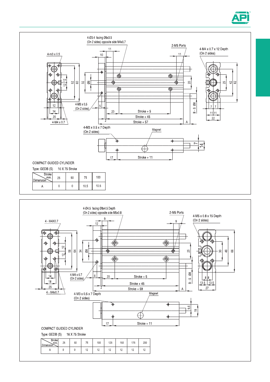
Compact Guided Cylinders

Bores from 10 to 63 mm


Ø 20 - Ø 25

Ø 20

Ø 25

1.23.4

1

1.23.5

Compact Guided Cylinders

Bores from 10 to 63 mm


Ø 32 - Ø 40

Ø 32


Ø 40

Compact Guided Cylinders

Bores from 10 to 63 mm


Ø 50 - Ø 63


Ø 50


Ø 63

1.23.6

1

Guiding and stopper cylinders

Bores from 12 to 63 mm


Double acting

For the magnetic reed switches type ASC see from page 1.110.2.

20

/

30

GPB

Bore

/

Stroke

Type

Option

Techinical data

Fluid

Compressed filtered air with or without lubrication. Lubrication, if started, must be continued.

Bore

Ø 12

Ø 16

Ø 20

Ø 20

Ø 32

Ø 40

Ø 50

Ø 63

Pressure range

2 ÷ 7 bar

Temperature range

- 10 °C ÷ + 60°C

Bore 

(mm)

Standard stroke 

GPB

Standard stroke 

GPS

12

10, 20, 30, 40, 50, 75, 100

10, 20, 30, 40, 50, 75, 100

16

10, 20, 30, 40, 50, 75, 100

10, 20, 30, 40, 50, 75, 100

20

20, 30, 40, 50, 75, 100, 125, 150, 175

20, 30, 40, 50, 75, 100, 125, 150, 175

25

20, 30, 40, 50, 75, 100, 125, 150, 175

20, 30, 40, 50, 75, 100, 125, 150, 175

32

25, 50, 75, 100, 125, 150

25, 50, 75, 100, 125, 150

40

25, 50, 75, 100, 125, 150

25, 50, 75, 100, 125, 150

50

25, 50, 75, 100, 125, 150

25, 50, 75, 100, 125, 150

63

25, 50, 75, 100, 125, 150

25, 50, 75, 100, 125, 150

Standard executions

Version

Symbol

Type

Double acting, magnetic 
self lubricating bushings

GPB

Double acting, magnetic 
spherical bushings

GPS

Options

Suffix

Special on request

/ S

How to order: 20/30 GPB

1.23.50

Series of guiding and stopper cylinders, magnetic as standard.
This cylinder are made of uni-body aluminium alloy with high
anti-rotation, torsion and side load features.
Piston with magnet is standard and the body, a one piece, is
provided with grooves allowing the mounting of the magnetic
reed switch without further brackets; this makes the magnetic
sensor not protrude outside the body itself.
The bottom plates are provided with elastic cushionings.

GPB Ø12 ÷ Ø16

GPB Ø20 ÷ Ø25

5

2

8

17

18

15

16

12

9

7

13

4

6

21

1

3

20

30mm 

≤ st.

st. > 30mm

30mm 

≤ st.

st. 

30mm

19

10

22

14

25

25

30mm 

≤ st.

30mm > st. ≥ 100mm

st. > 100mm

30mm 

≥ st.

30mm > st. ≥

 100mm

st. > 100mm

24

24

19

10

21

1

3

20

22

25

25

5

2

8

17

18

15

16

12

9

7

13

4

6

23

14

1.23.51

Guiding and stopper cylinders

Bores from 12 to 63 mm

  Materials

 Materials 


1

  Rod cover 

Brass (Ø12) - Hard anodised aluminium alloy (Ø16÷Ø25) 

AN

  Rubber lining 

Nitrile rubber NBR


2

  Piston 

Hard anodised aluminium alloy 

AO

  Cylinder gasket  Nitrile rubber NBR


3

  Piston rod 

Stainless steel (Ø12) - Carbon steel (Ø16÷Ø32) 

AP

  Rubber lining 

Nitrile rubber NBR


4

  Cylinder tube 

Hard anodised aluminium alloy 

AQ

  Magnet 

Magnetic material


5

  Magnet holder 

Hard anodised aluminium alloy 

AR

  Oilless bearing 

Oil-impregnated sintered alloy


6

  Head cover 

Hard anodised aluminium alloy 

AS

  Linear bearing 

Special steel


7

  Guide plate 

Carbon steel nickel plating 

BT

  Hexagon socket head screw  Carbon steel nickel plating


8

  Guide stem 

Carbon steel (GPB) - Special steel (GPS) 

BK

  Screw 

Carbon steel nickel plating


9

  Retaining ring 

Carbon steel nickel plating 

BL

  Screw 

Carbon steel nickel plating


AT

  Retaining ring 

Carbon steel nickel plating 

BM

  O-ring 

Nitrile rubber NBR


AK

  Oilless bearing 

Oil-impregnated sintered alloy 

BN

  Stroke pad 

Hard anodised aluminium alloy


AL

  Rod packing 

Nitrile rubber NBR 

BO

  Dust cover 

Aluminium alloy (Ø12÷Ø16)


AM

  Piston packing 

Nitrile rubber NBR 


Carbon steel - NBR (Ø20÷Ø25)

Type: 

GPB - GPS

(Bores Ø12 ÷ Ø25)

1

GPB Ø32 ÷ Ø63

s

t.

50mm

s

t.

<

50mm

100mm

<

s

t.

100mm

100mm

<

s

t.

19

10

5

2

8

17

18

15

16

9

12

21

13

4

6

7

1

3

20

23

22

Ø32~Ø63

s

t.

50mm

Ø32~Ø63

Ø32~Ø63

s

t.

<

50mm

100mm

Ø32~Ø63

24

Ø32~Ø63

Ø32~Ø63

Ø63

11

24

Ø63

11

14

25

25

1.23.52

Guiding and stopper cylinders

Bores from 12 to 63 mm

  Materials

 Materials


1

  Rod cover 

Brass (Ø12) - Hard anodised aluminium alloy (Ø16÷Ø25) 

AN

  Rubber lining 

Nitrile rubber NBR


2

  Piston 

Hard anodised aluminium alloy 

AO

  Cylinder gasket 

Nitrile rubber NBR


3

  Piston rod 

Stainless steel (Ø12) - Carbon steel (Ø16÷Ø32) 

AP

  Rubber lining 

Nitrile rubber NBR


4

  Cylinder tube 

Hard anodised aluminium alloy 

AQ

  Magnet 

Magnetic material


5

  Magnet holder 

Hard anodised aluminium alloy 

AR

  Oilless bearing 

Oil-impregnated sintered alloy


6

  Head cover 

Hard anodised aluminium alloy 

AS

  Linear bearing 

Special steel


7

  Guide plate 

Carbon steel nickel plating 

BT

  Hexagon socket head screw  Carbon steel nickel plating


8

  Guide stem 

Carbon steel (GPB) - Special steel (GPS) 

BK

  Screw 

Carbon steel nickel plating


9

  Retaining ring 

Carbon steel nickel plating 

BL

  Screw 

Carbon steel nickel plating


AT

  Retaining ring 

Carbon steel nickel plating 

BM

  O-ring 

Nitrile rubber NBR


AK

  Oilless bearing 

Oil-impregnated sintered alloy 

BN

  Stroke pad 

Hard anodised aluminium alloy


AL

  Rod packing 

Nitrile rubber NBR 

BO

  Dust cover 

Carbon steel - NBR


AM

  Piston packing 

Nitrile rubber NBR

Type: 

GPB - GPS

(Bores Ø6 ÷ Ø32)

1.23.53

Guiding and stopper cylinders

Bores from 12 to 63 mm


Standard dimensions

MM depth ML (4x)

O (2x)

Type: 

GPB - GPS

(Bores Ø12 ÷ Ø25)

XX View

Groove dimensions

Bore

a

b

c

d

e

Ø12

4,4

7,4

3,7

2

6,2

Ø16

4,4

7,4

3,7

2,5

6,7

Ø20

5,4

8,4

4,5

2,3

7,3

Ø25

5,4

8,4

4,5

3

8,2

Ø 

mm

Stroke

A

B

C

D

DA

DB

E

FA

FB

H

J1

J2

L

MM

ML

NN

O

P

Q

GPB GPS

12

10-100

56

22

29

58

6

8

6

26

8

5

M4

13

13

42

M4

10

M4

M5

11

7.5

16

62

25

33

64

8

10

8

30

8

5

M4

15

15

46

M5

12

M5

M5

11

8

20

20-175

81

30

37

83

10

12

10

36

10

6

M5

18

18

53

M5

13

M5

1/8”

11.5

9

25

91

38

37.5

93

12

16

12

42

10

6

M5

21

21

53.5

M6

15

M6

1/8”

11.5

9

Ø 

mm

Stroke

QA QB PW TT

U

VA

VB

S1 S2 R1 R2

± 0.02

XA 

H7

XB VC

st. 

≤ 30

30 < st. 

 100

st. > 100

st. 

 30

30 < st. 

 100

st. > 100

12

10-100

12

7.5

18

37

41

20

40

-

15

25

-

14 18 48 50

23

3

3.5 3

16

14

10

19

38

46

24

44

-

17

27

-

16 22 54 56

24

3

3.5 3

20

20-175

12.5 11.5 25

44

54

24

44

120

29

39

77

18 24 70 72

28

3

3.5 3

25

12.5 13.5 28.5 50

64

24

44

120

29

39

77

26 30 78 82

34

4

4.5 3

Ø 

mm

Stroke

XL

YY

YL

Z

ZA

ZB

ZL

GPB

GPS

K

LL

K

LL

st. 

≤ 50

st. > 50

st. 

≤ 50

st. > 50

st. 

 30

30 < st. 

 100

st. > 100

st. 

 30

30 < st. 

 100

st. > 100

12

10-100

6

M5

10

5

4.3

8

4.5

0

15

42

57

0

15

-

42

57

-

16

6

M5

10

5

4.3

8

4.5

0

22

46

68

0

22

-

46

68

-

20

20-175

6

M6

12

17

5.6

9.5

5

0

28

53

81

0

28

52

53

81

105

25

6

M6

12

17

5.6

9.5

5.5

0

29

53.5

82.5

0

31

50

53.5

84.5

103.5

1

1.23.54

Guiding and stopper cylinders

Bores from 12 to 63 mm


Standard dimensions

Type: 

GPB - GPS

(Bores Ø32 ÷ Ø63)

XX View

Groove dimensions

Bore

a

b

c

d

e

Ø32

6.5

10.5 5.35

3.5

9.5

Ø40

6.5

10.5 5.35

4

11

Ø50

8.5

13.5

7.5

4.5

13.5

Ø63

11

17.8

10

7

18.5

Ø 

mm

Stroke

A

B

C

D

DA

DB

E

FA

FB

H

J1

J2

L

MM

ML

NN

O

P

Q

GPB GPS

32

25, 50, 

75, 100, 

125, 

150

110

44

37.5 112

16

20

16

48

12

10

M6

24

24

59.5

M8

20

M8

1/8”

11.5

10

40

118

44

44

120

16

20

16

54

12

10

M6

27

27

66

M8

20

M8

1/8”

14

11

50

146

60

44

148

20

25

20

64

16

12

M8

32

32

72

M10

22

M10

1/4”

12

11

63

158

70

49

162

20

25

20

78

16

12

M10

39

39

77

M10

22

M10

1/4”

16.5

13

Ø 

mm

Stroke

QA QB PA PW TT U

VA

VB

S1 S2 R1 R2

± 0.02

XA 

H7

XB

25

50-100

st. > 100

25

50-100

st. > 100

32

25, 50, 

75, 100, 

125, 

150

5

16.5 11.5 34

63 78

24

48

124

33

45

83

30 34 96

98

42

4

4.5

40

11

18

14

38

72 86

24

48

124

34

46

84

30 40 104 106 50

4

4.5

50

9

21.5 14

47

92 110

24

48

124

36

48

86

40 46 130 130 66

5

6

63

14

28 16.5 55 110 124

28

52

128

38

50

88

50 58 130 142 80

5

6

Ø 

mm

Stroke

XC

XL

YY

YL

Z

ZA

ZB

ZL

GPB

GPS

K

LL

K

LL

25, 50

st. > 50

25, 50

st. > 50

25, 50

75, 100

st. > 100

25, 50

75, 100

st. > 100

32

25, 50, 

75, 100, 

125, 

150

3

6

M8

16

21

6.5

11

7.5

8

45

67.5

104.5

8

45

65

67.5

104.5

124.5

40

3

6

M8

16

22

6.5

11

7.5

1.5

38.5

67.5

104.5

1.5

38.5

58.5

67.5

104.5

124.5

50

4

8

M10 20

24

8.5

14

9

6.5

48.5

78.5

120.5

6.5

48.5

68.5

78.5

120.5

140.5

63

4

8

M10 20

24

8.5

14

9

1.5

43.5

78.5

120.5

1.5

43.5

63.5

78.5

120.5

140.5

1

Twin-rod cylinders

Bores from 6 to 32 mm


Double acting

20

/

30

GSB

Bore

/

Stroke

Type

Option

Technical data

Fluid

Compressed filtered air with or without lubrication. Lubrication, if started, must be continued.

Bore

Ø 6

Ø 10

Ø 16

Ø 20

Ø 25

Ø 32

Pressure range

1.5 ÷ 7 bar

1 ÷ 7 bar

0.5 ÷ 7 bar

Speed range

30÷300 mm/sec.

30÷500 mm/sec.

Adjustable stroke

0 ÷ -5 mm

Temperature range

- 10 °C ÷ + 60°C

Bore 

(mm)

Standard stroke 

GSB

Standard stroke 

GSS

6

10, 20, 30, 40, 50

10, 20, 30, 40, 50

10

10, 15, 20, 25, 30, 35, 40, 45, 50

10, 15, 20, 25, 30, 35, 40, 45, 50

16

10, 15, 20, 25, 30, 35, 40, 45, 50, 60, 

70, 75, 80, 90, 100, 125, 150

10, 15, 20, 25, 30, 35, 40, 45, 50, 60, 

70, 75, 80, 90, 100, 125, 150

20

10, 15, 20, 25, 30, 35, 40, 45, 50, 60, 

70, 75, 80, 90, 100, 125, 150

10, 15, 20, 25, 30, 35, 40, 45, 50, 60, 

70, 75, 80, 90, 100, 125, 150

25

10, 15, 20, 25, 30, 35, 40, 45, 50, 60, 

70, 75, 80, 90, 100, 125, 150

10, 15, 20, 25, 30, 35, 40, 45, 50, 60, 

70, 75, 80, 90, 100, 125, 150

32

10, 15, 20, 25, 30, 35, 40, 45, 50, 60, 

70, 75, 80, 90, 100, 125, 150

10, 15, 20, 25, 30, 35, 40, 45, 50, 60, 

70, 75, 80, 90, 100, 125, 150

Standard executions

Version

Symbol

Type

Double acting, magnetic 
self lubricating bushings

GSB

Double acting, magnetic 
spherical bushings

GSS

Options

Suffix

Special on request

/ S

How to order: 20/30 GSB 

1.24.1

Series of twin-rod cylinders magnetic as standard.
This cylinder is of two-axle mode with double thrust force and
smooth and precise operation.
A one piece body is provided with grooves allowing the
mounting of the magnetic reed switch without further brackets;
this makes the magnetic sensor not protrude outside the body
itself.
The bottom plates are provided with elastic cushionings.

For the magnetic reed switches type ASV see from page 1.110.1.

Twin rod compact guided cylinders

Bores from 6 to 32 mm

 Materials

1.24.2

5

2

8

17

18

15

16

12

9

7

13

4

6

21

1

3

20

10

22

14

24

25

7

1

3

3

20

20

9

21

19

15

11

11

15

18

5

5

26

23

2

10

19

14

6

22

9

21

18

19

22

24

4

14

24

4

14

24

23

16

16

1

16

26

23

Type: 

GSB - GSS

(Bore Ø12 ÷ Ø25)

Materials

1

Rod cover

Hard anodised aluminium alloy

2

Head cover

Hard anodised aluminium alloy

3

Piston

Brass (Ø6) - Aluminium alloy (Ø10 ÷ Ø32)

4

Piston rod

Stainless steel (GSB Ø6 ÷ Ø10)
Carbon steel ( GSB Ø16 ÷ Ø32)
Special steel (GSS)

5

Cylinder tube

Hard anodised aluminium alloy

6

Magnet holder

Stainless steel

7

Bearing holder

Brass (Ø6) - Aluminium alloy (Ø10 ÷ Ø32)

8

Bearing holder

Aluminium alloy (Ø10 ÷ Ø32)

9

Guide plate

Hard anodised aluminium alloy

AT

Nut

Carbon steel nickel plating

AK

O-ring

Nitrile rubber NBR

AL

Oilless bearing

Oil-impregnated sintered alloy

AM

Linear bearing

Special steel

AN

Rod packing

PU

AO

Piston packing

Nitrile rubber NBR

AP

Cylinder gasket

Nitrile rubber NBR

AQ

Magnet

Magnetic material

AR

Rubber pillar

Nitrile rubber NBR

AS

Adjusting screw

Stainless steel

BT

Rubber lining

Nitrile rubber NBR

BK

Screw

Carbon steel nickel plating

BL

Lock nut

Carbon steel nickel plating

BM

Set screw

Carbon steel

BN

Retaining ring

Carbon steel nickel plating

BO

Steel pad

Stainless steel

BP

Port gasket

Nitrile rubber NBR

1

Twin rod compact guided cylinders

Bores from 6 to 32 mm


Standard dimensions

A+corsa

B+corsa

Det. B

M4 (x2)

M5 depth 4.5 (2x)

M5 depth 4.5 (4x)

M3 depth 4.5 (2x)

M3 depth 4.5 (4x)

M3 (2x)

M3 depth 4.5 (2x)

ø 3.4 -
ø 6 depth 3.3 (x2)

N (2x)

UU (4x)

F (2x)

V (4x)

W (2x)

N (2x)

Type: 

GSB-GSS

(Bore Ø10 - Ø16)

Type: 

GSB

(Bore Ø6)

1.24.3

Ø 

mm

A

B

C

D

E

F

G

H

I

J

L

M

N

NN

P

Q

QQ

R

W

V

10

46

17

44

15

7.5 M4

35

19

4

8

20 Ø 3.4 - Ø 6 depth 3.3 M3 depth 5 Ø 6

32

8.5

7

30

M4 depth 8 M3 depth 4.5

16

58

20

56

18

9

M5

45

24

5

10

30 Ø 4.3 - Ø 8 depth 4.4 M4 depth 6  Ø 8

47

10

10

36

M5 depth 9 M4 depth 5

Ø 

mm

UU

Stroke = 10

Stroke = 15

Stroke = 20

Stroke = 25

Stroke = 30

Stroke = 35

Stroke = 40

Stroke = 45

Stroke = 50

SS

Z

ZZ SS

Z

ZZ SS

Z

ZZ SS

Z

ZZ SS

Z

ZZ SS

Z

ZZ SS

Z

ZZ SS

Z

ZZ SS

Z

ZZ

10 M5 depth 4.5 65

30

82

70

30

87

75

30

92

80

30

97

85

40 102 90

40 107 95

40 112 100 40 117 105 40 122

16 M5 depth 5.5 70

25

89

75

25

94

80

25

99

85

25 104 90

35 109 95

35 114 100 35 119 105 35 124 110 35 129

Ø 

mm

Stroke = 60

Stroke = 70

Stroke = 75

Stroke = 80

Stroke = 90

Stroke = 100

Stroke = 125

Stroke = 150

SS

Z

ZZ SS

Z

ZZ SS

Z

ZZ SS

Z

ZZ SS

Z

ZZ SS

Z

ZZ SS

Z

ZZ SS

Z

ZZ

10

-

-

-

-

-

-

-

-

-

-

-

-

-

-

-

-

-

-

-

-

-

-

-

-

16

120 45 139 130 45 149 135 45 154 140 45 159 150 55 169 160 55 179 185 80 204 210 80 229

Ø 

mm

Stroke = 10

Stroke = 20

Stroke = 30

Stroke = 40

Stroke = 50

S

Z

SS

ZZ

S

Z

SS

ZZ

S

Z

SS

ZZ

S

Z

SS

ZZ

S

Z

SS

ZZ

6

23

15

55

68,5

33

20

65

78,5

43

25

75

88,5

53

30

85

98,5

63

35

95

108,5

F (2x)

W (2x)

N (2x)

N (2x)

V (8x)

UU (4x)

Type: 

GSB - GSS

(Bore Ø20 - Ø32)

Twin rod compact guided cylinders

Bores from 6 to 32 mm


Standard dimensions

1.24.4

Ø 

mm

A

B

C

D

E

F

G

H

I

J

K

L

M

N

NN 
(Ø)

P

Q

QQ

R

T

TT

U

20

64

25

62

23 11.5 M5

50

28

6

12

12

30 Ø 5.5 - Ø 9.5 depth 5.4 M4 depth 7.5dp 10

50

7.75 12.5

45

9.5

6

9

25

80

30

78

28

14

M6

60

35

6

12

12

30 Ø 6.8 - Ø 11 depth 6.3 M5 depth 7.5dp  12

60

8.5

15

44.5

13

9

10

32

98

38

96

36

18

M6

75

44

8

16

14

30 Ø 6.8 - Ø 11 depth 6.3 M5 depth 10dp

16

74

9

19

52.5

20

11

12

Ø 

mm

UU

V

W

Stroke = 10

Stroke = 15

Stroke = 20

Stroke = 25

Stroke = 30

Stroke = 35

Stroke = 40

SS

Z

ZZ SS

Z

ZZ SS

Z

ZZ SS

Z

ZZ SS

Z

ZZ SS

Z

ZZ SS

Z

ZZ

20

M5

M4 depth 5.5 M6 depth 10dp 80

30 104 85

30 109 90

30 114 95

30 119 100 40 124 105 40 129 110

40

134

25

1/8 gas

M5 depth 7.5 M8 depth 16dp 82

30 106 87

30

111

92

30 116 97

30 121 102 40 126 107 40 131 112 40 136

32

1/8 gas

M5 depth 7.5 M8 depth 16dp 92

40 122 97

40 127 102 40 132 107 40 137 112 50 142 117 50 147 122 50 152

Ø 

mm

Stroke = 45

Stroke = 50

Stroke = 60

Stroke = 70

Stroke = 75

Stroke = 80

Stroke = 90 Stroke = 100 Stroke = 125 Stroke = 150

SS Z

ZZ SS Z

ZZ SS Z

ZZ SS Z

ZZ SS Z

ZZ SS Z

ZZ SS Z

ZZ SS Z

ZZ SS Z

ZZ SS Z

ZZ

20

115 40 139 120 40 144 130 60 154 140 60 164 145 60 169 150 60 174 160 60 184 170 60 194 195 85 219 220 85 244

25

117 40 141 122 40 146 132 60 156 142 60 166 147 60 171 152 60 176 162 60 186 172 60 196 197 85 221 222 85 246

32

127 50 157 132 50 162 142 70 172 152 70 182 157 70 187 162 70 192 172 70 202 182 70 212 207 95 237 232 95 262

1

1.26.1

Rodless Cylinders

Bores from 18 to 63 mm


Double acting

Rodless cylinders, magnetic as standard.
Cylinders with direct power transmission through the tube slot onto 
the yoke. The new cushionings are adjustable at both ends; the 
flow rate is regulated from 0 to 100% by turning a pin of an angle of  
90°. The new barrel with high resistance to deflection is provided 
with grooves for fixing various accessories.
The magnetic switches can be fixed by a bracket or directly in the 
tube; the reed switch will not protrude out the barrel profile.
The short cylinder type S2, in comparison to the standard cylinder 
- 0 - stroke, is up to 42% shorter; the total fitting length is therefore 
reduced and the cylinder is more compact and money-saving.

For the magnetic reed switches ASV-ASC 

see page 1.26.40.

For mounting accessories 

see from page 1.26.28.

How to order: 32 / 1000 S1U

The options can be combined (when this is possible).

32

/

1000

S1

U

Bore

/

Stroke

Type

Option

Bore 

(mm)

Standard strokes 

(mm)

Max stroke 

(mm)

Cushion 

length 

(mm)

Theoretical 

force at 6 bar 

(N) 

Weight 

at 0 stroke 

Type S1 (g)

Weight 

at 0 stroke 

Type S2 (g)

Weight for 

every 10 mm 

stroke (g)

18

from 10 to 6000

9000

15

140

300

200

15

25

18

270

600

400

26

32

24

440

1100

700

36

40

34

680

1800

1200

48

50

40

1060

3200

2000

74

63

49

1680

5600

3200

101

Standard executions

Version

Symbol

Type

Standard

S1

Short (for light loads)

S2

Options 

Suffix

Both connections 
on one head

from bore 25 mm.

P

Carriage with 
integral brake

(see page 1.26.35)

B

Special versions on request

/ S

For parameters of the loads and moments
see from page 1.26.25.
For seal kits see from page 1.26.21.

Technical data

Fluid

Compressed filtered air with or without lubrication. Lubrication, if started, must be continued.

Pressure

1,5 ÷ 9 bar

Temperature range

-10 °C ÷ + 70°C

Materials

Heads: 

Anodised aluminium

Tube: 

Anodised aluminium

Seals: 

Polyurethane - Piston: monobloc/yoke: Aluminium

Internal strip: 

Nylon

External strip: 

Stainless steel AISI 304

Raschiapolvere: PVC

1.26.2

Rodless Cylinders

Bores from 18 to 63 mm


Double acting

AM

L = 2 x A + STROKE

5x5

Type: 

S1

L = 2 x A + STROKE

5x5

Type: 

S2

Ø 

mm

A

AF AM

B

C CA CB

D

DA DB DC DD

E

F

FE

G

J

M

N

Ø 
O


S

T


U

W

18

80

50

10 16,5 6,5

-

-

M7x1/6 15,5

-

-

-

103

75

90

-

3

15,5

M3x6

3,5 23,5 M3x7

30

39

25

100

70

13

20 8,5

7

13

G1/8x8 25,5 14

28 18,5 131 100 116 50 3,5

20

M4x7

4,5 33

M4x9

42

53

32

120 100 16

20 8,5

7

13

G1/8x8

32

16 34,5 21

171 140 156 70 4,5

25

M5x9

5,5 41 M5x10

52

65

40

150 140 22

23

13 11 14,5 G1/4x12 37,5 18,5 41 29,5 220 180 200 90

5

33

M6x10

7

51 M6x12

63

79

50

180 180 29

23

13 12

14 G1/4x12 47,5 22,5 47,5 37

280 220 260 110 6,5

42 M8x12,5 7

63 M8x12

78

96

63

215 230 40

29

13 12,5 15,5 G3/8x12 59,5 24,5 59,5 44,5 333 280 313 140

8

54 M8 x 15

9

78 M8x12

93

113,5

Ø 

mm

A

AF AM

B

C CA CB

D

DA DB DC DD

E

F

FE

J

M

N

Ø 
O


S

T


U

W

18 57,5 15

10 16,5 6,5

-

-

M7x1/6

17,5

-

-

-

58

30

45

3

15,5

M3x6

3,5 23,5 M3x7

30

39

25 67,5 19

13

20 8,5

7

13

G1/8x8

25,5 14

28 18,5 66

35

51

3,5

20

M4x7

4,5 33

M4x9

42

53

32 77,5 35

16

20 8,5

7

13

G1/8x8

32 17,5 34,5 21

86

55

71

4,5

25

M5x9

5,5 41

M5x10

52

65

40

95

50

22

23

13 9,5 14,5 G1/4x12 37,5 20

42 29,5 110

70

90

5

33

M6x10

7

51

M6x12

63

79

50

105

46

29

23

13 9,5 14,5 G1/4x12 47,5 26

52

37

130

70

110 6,5

42 M8x12,5 7

63

M8x12

78

96

63

125

70

40

29

13 11 18,5 G3/8x12,5 59,5 30

62 44,5 153 100 133

8

54

M8x15

9

78

M8x12

93

113,5

1

1.26.10

Rodless Cylinders

Bores from 18 to 63 mm


Double acting

Rodless cylinders, magnetic as standard.
Cylinders with direct power transmission through the tube slot onto 
the yoke. The new cushionings are adjustable at both ends; the flow 
rate is regulated from 0 to 100% by turning a pin of an angle of 90°.
The new barrel is provided with grooves for fixing various accesso-
ries. The magnetic switches can be fixed by a bracket or directly 
in the tube; the reed switch will not protrude out the barrel profile.
The side carriage (which can also be installed at a later date) is 
adjustable and this allows to use the cylinder with heavier loads; the 
guide moves by Teflon slides, fixed in the grooves of the tube. The 
short guided cylinders type S5, in comparison to the standard cylin-
der - 0 - stroke, is up to 42% shorter; the total fitting length is there-
fore reduced and the cylinder is more compact and money-saving.

For the magnetic reed switches ASV-ASC 

see page 1.26.40.

For mounting accessories 

see from page 1.26.28.

How to order: 50 / 1000 S6U

The options can be combined (when this is possible).

Bore 

(mm)

Standard 

strokes 

(mm)

Max stroke 

(mm)

Cushion 

length 

(mm)

Theoretical 

force at 6 bar 

(N) 

Weight 

at 0 stroke 

Type S3 (g)

Weight 

at 0 stroke 

Type S5 (g)

Weight 

at 0 stroke 

Type S6 (g)

Weight for 

every 10 mm 

stroke (g)

18

from 10 to 

6000

9000

15

140

400

250

500

15

25

18

270

900

550

1200

26

32

24

440

1500

1100

1900

36

40

34

680

2800

1700

3800

48

50

40

1060

4900

2850

6600

74

63

49

1680

8000

4400

10400

101

Standard executions

Version

Symbol

Type

Guided

S3

Short guided 
(for light loads)

S5

Double guide

S6

Options 

Suffix

Both connections 
on one head

from bore 25 mm.

U

Special versions on request

/ S

For parameters of the loads and moments
see from page 1.26.25.
For seal kits see from page 1.26.21.

50

/

1000

S6

U

Bore

/

Stroke

Type

Option

Technical data

Fluid

Compressed filtered air with or without lubrication. Lubrication, if started, must be continued.

Pressure

2  ÷ 8 bar

Temperature range

-20 °C ÷ + 80°C

Materials

Heads: 

Anodised aluminium

Tube: 

Anodised aluminium

Seals: 

Polyurethane - Piston: monobloc/yoke: Aluminium

Internal strip: 

Nylon

External strip: 

Stainless steel AISI 304

Wiper ring: 

PVC

Carriage: Aluminium


Content      ..     4      5      6      7     ..