HNC-08M CNC SYSTEM CNC Milling System. Operation Manual (V1.22 2011/01) - page 7
Alarm Number: No. 93
Reason: Fourth-axis motor overspeed
Solution: Reset system to clear up
Alarm Number: No. 94
Reason: Fifth-axis motor overspeed
Solution: Reset system to clear up
Alarm Number: No. 95
Reason: Sixth-axis motor overspeed
Solution: Reset system to clear up
Alarm Number: No. 96
Reason: Seventh-axis motor overspeed
Solution: Reset system to clear up
Alarm Number: No. 97
Reason: Eighth-axis motor overspeed
Solution: Reset system to clear up
Alarm Number: No. 100
Reason: X-axis does not return to reference point
Solution: Implement the X-axis manual returning reference point, the alarm will be
automatically cleared up after finished.
Alarm Number: No. 101
Reason: Y-axis does not return to reference point
Solution: Implement the Y-axis manual returning reference point, the alarm will be
automatically cleared up after finished.
174
Alarm Number: No. 102
Reason: Z-axis does not return to reference point
Solution: Implement the Z-axis manual returning reference point, the alarm will be
automatically cleared up after finished.
Alarm Number: No. 103
Reason: Fourth-axis does not return to reference point
Solution: Implement the fourth-axis manual returning reference point, the alarm will
be automatically cleared up after finished.
Alarm Number: No. 104
Reason: Fifth-axis does not return to reference point
Solution: Implement the fifth-axis manual returning reference point, the alarm will
be automatically cleared up after finished.
Alarm Number: No. 105
Reason: Sixth-axis does not return to reference point
Solution: Implement the sixth-axis manual returning reference point, the alarm will
be automatically cleared up after finished.
Alarm Number: No. 106
Reason: Seventh-axis does not return to reference point
Solution: Implement the seventh-axis manual returning reference point, the alarm
will be automatically cleared up after finished.
Alarm Number: No. 107
Reason: Eighth-axis does not return to reference point
Solution: Implement the eighth-axis manual returning reference point, the alarm will
be automatically cleared up after finished.
175
Alarm Number: No. 110
Reason: X-axis electronic gear ratio setting error
Solution: Check X-axis electronic gear ratio setting. Note that both the numerator
and the denominator should not be less than 1×10⁻⁶.
Alarm Number: No. 111
Reason: Y-axis electronic gear ratio setting error
Solution: Check Y-axis electronic gear ratio setting. Note that both the numerator
and the denominator should not be less than 1×10⁻⁶.
Alarm Number: No. 112
Reason: Z-axis electronic gear ratio setting error
Solution: Check Z-axis electronic gear ratio setting. Note that both the numerator
and the denominator should not be less than 1×10⁻⁶.
Alarm Number: No. 113
Reason: Fourth-axis electronic gear ratio setting error
Solution: Check the fourth-axis electronic gear ratio setting. Note that both the
numerator and the denominator should not be less than 1×10⁻⁶.
Alarm Number: No. 114
Reason: Fifth-axis electronic gear ratio setting error
Solution: Check the fifth-axis electronic gear ratio setting. Note that both the
numerator and the denominator should not be less than 1×10⁻⁶.
Alarm Number: No. 115
Reason: Sixth-axis electronic gear ratio setting error
Solution: Check the sixth-axis electronic gear ratio setting. Note that both the
numerator and the denominator should not be less than 1×10⁻⁶.
176
Alarm Number: No. 116
Reason: Seventh-axis electronic gear ratio setting error
Solution: Check the seventh-axis electronic gear ratio setting. Note that both the
numerator and the denominator should not be less than 1×10⁻⁶.
Alarm Number: No. 117
Reason: Eighth-axis electronic gear ratio setting error
Solution: Check the eighth-axis electronic gear ratio setting. Note that both the
numerator and the denominator should not be less than 1×10⁻⁶.
Alarm Number: No. 120
Reason: X-axis screw pitch setting error
Solution: Check the X-axis screw pitch setting value, which should not be less than
0.1.
Alarm Number: No. 121
Reason: Y-axis screw pitch setting error
Solution: Check the Y-axis screw pitch setting value, which should not be less than
0.1.
Alarm Number: No. 122
Reason: Z-axis screw pitch setting error
Solution: Check the Z-axis screw pitch setting value, which should not be less than
0.1.
Alarm Number: No. 123
Reason: Fourth-axis degrees setting error per revolution
Solution: Check the fourth-axis degrees setting value per revolution, which should
not be less than 0.1.
177
Alarm Number: No. 124
Reason: Fifth-axis degrees setting error per revolution
Solution: Check the fifth-axis degrees setting value per revolution, which should not
be less than 0.1.
Alarm Number: No. 125
Reason: Sixth-axis degrees setting error per revolution
Solution: Check the sixth-axis degrees setting value per revolution, which should
not be less than 0.1.
Alarm Number: No. 126
Reason: Seventh-axis degrees setting error per revolution
Solution: Check the seventh-axis degrees setting value per revolution, which should
not be less than 0.1.
Alarm Number: No. 127
Reason: Eighth-axis degrees setting error per revolution
Solution: Check the eighth-axis degrees setting value per revolution, which should
not be less than 0.1.
Alarm Number: No. 130
Reason: X-axis encoder pulses number setting error
Solution: Check the X-axis pulses number setting value per revolution, which
should not be less than 1.
Alarm Number: No. 131
Reason: Y-axis encoder pulses number setting error
Solution: Check the Y-axis pulses number setting value per revolution, which should
not be less than 1.
178
Alarm Number: No. 132
Reason: Z-axis encoder pulses number setting error
Solution: Check the Z-axis pulses number setting value per revolution, which
should not be less than 1.
Alarm Number: No. 133
Reason: Fourth-axis encoder pulses number setting error
Solution: Check the fourth-axis pulses number setting value per revolution, which
should not be less than 1.
Alarm Number: No. 134
Reason: Fifth-axis encoder pulses number setting error
Solution: Check the fifth-axis pulses number setting value per revolution, which
should not be less than 1.
Alarm Number: No. 135
Reason: Sixth-axis encoder pulses number setting error
Solution: Check the sixth-axis pulses number setting value per revolution, which
should not be less than 1.
Alarm Number: No. 136
Reason: Seventh-axis encoder pulses number setting error
Solution: Check the seventh-axis pulses number setting value per revolution, which
should not be less than 1.
Alarm Number: No. 137
Reason: Eighth-axis encoder pulses number setting error
Solution: Check the eighth-axis pulses number setting value per revolution, which
should not be less than 1.
179
Alarm Number: No. 160
Reason: when do tool measuring, system doesn’t detect the measuring head signal in
the process of measuring the checking instrument by G31.X command.
Solution: Check the measuring head signal of the checking instrument is normal.
Alarm Number: No. 300
Reason: R plane is not specified
Solution:
Alarm Number: No. 301
Reason: Bottom coordinate is not specified
Solution:
Alarm Number: No. 305
Reason: Feed quantity is not specified
Solution:
Alarm Number: No. 306
Reason: Retract quantity is not specified
Solution:
Alarm Number: No. 307
Reason: Pitch is not specified
Solution:
Alarm Number: No. 308
Reason: Spindle rotational speed is not specified
Solution:
180
Alarm Number: No. 310
Reason: The R plane should be on top of the Z plane
Solution:
181
13.3Appendix Three, Machine Tool Structure Code
For the machine tool without rotational axis, the structure code of tool swing head
and workbench are 0. For the machine tool which has rotational axis, the rotatinal axis’s
structure has tool swing head and workbench types, which can be set separately.
For the rotational axis in each machine tool structure form, please according to the
arrowhead shown in the figure to define the rotational positive and negative direction(the
direction of the arrowhead shown is the rotational positive direction). If the rotational
direction definition is incorrect, system can’t execute the RTCP control correctly.
The direction of tool swing head rotational axis is defined by the right hand rule in
the tool coordinate system, namely go down the rotational axis’s direction to see, the
rotational axis’s direction is clockwise. The direction of workbench rotational axis is the
opposite direction of swing head direction confirmed by the above principle.
The unlisted machine tool structure form in this appendix, system doesn’t support
the RTCP control, do not use.
13.3.1 Tool Swing Head Structure
1、Single Swing Head A-axis Structure(Structure code: 10A0)
Tool rotates around X-axis, as the following figure shown.
182
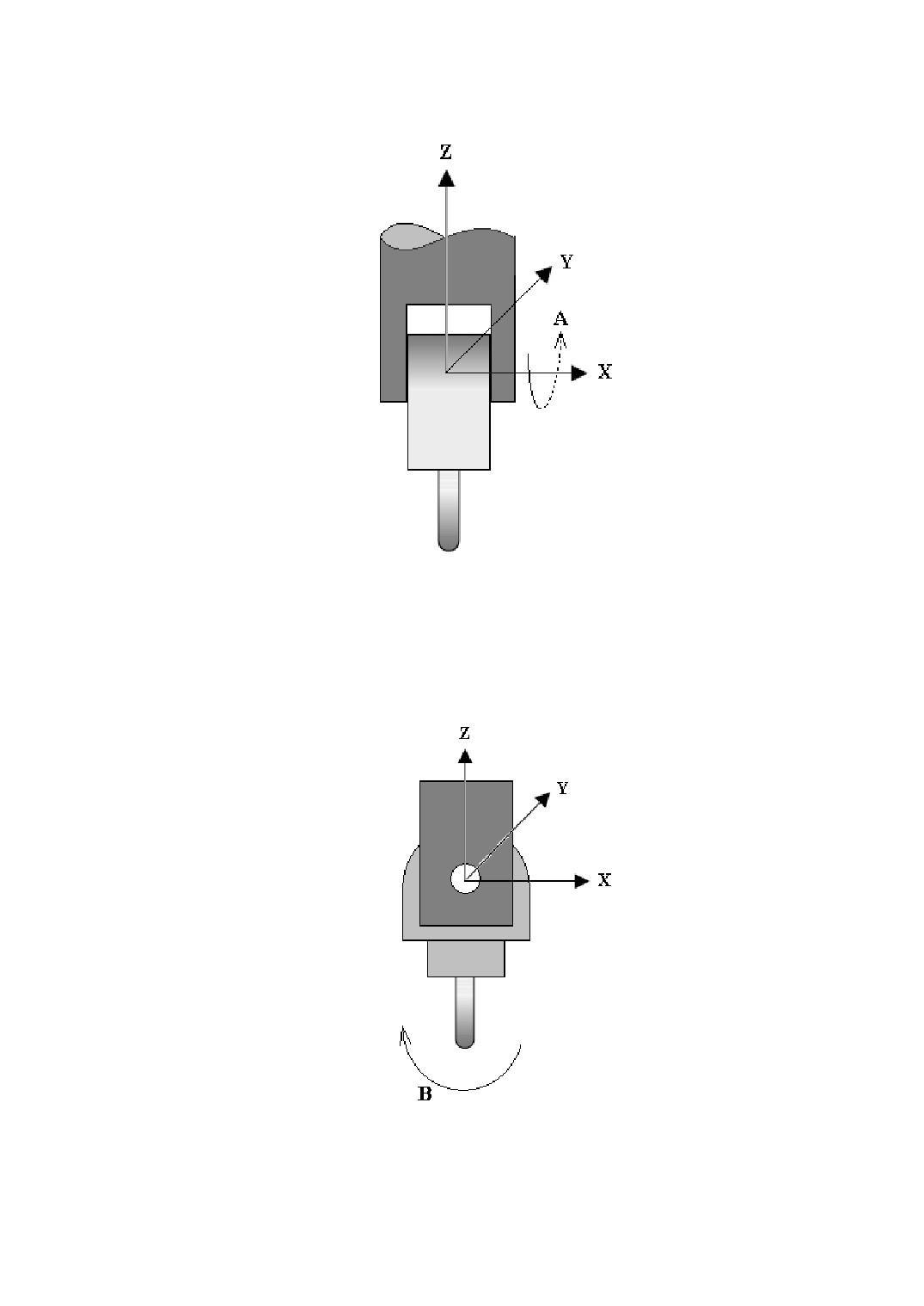
Figure 13-1 Single Swing Head A-axis Structure
2、Single Swing Head B-axis Structure(Structure code: 10B0)
Tool rotates around Y-axis, as the following figure shown.
Figure 13-2 Single Swing Head B-axis Structure
183
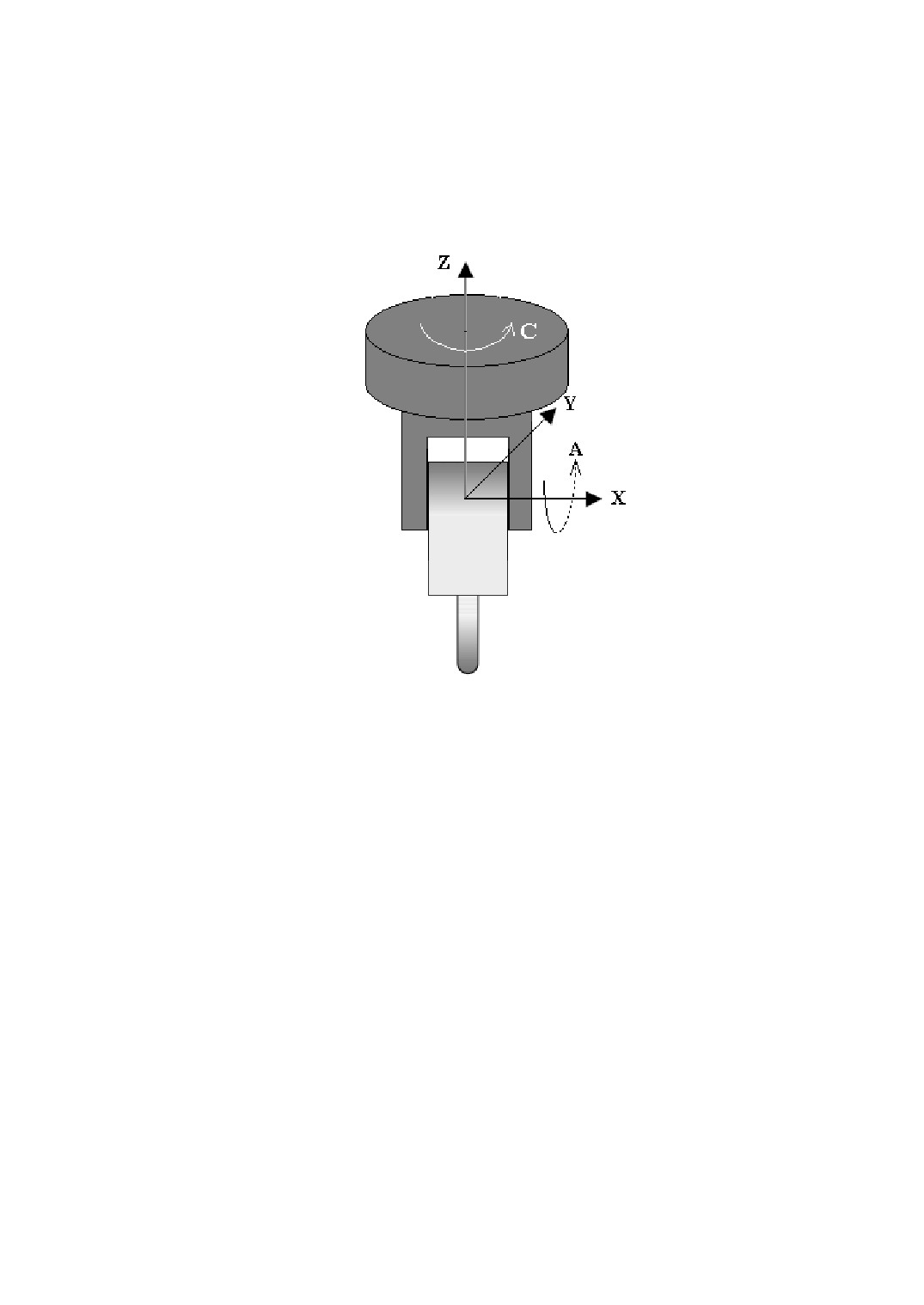
3、Double Swing Head C, A-axis Structure, C-axis driving, A-axis
driven(structure code: 1CA0)
Tool rotates around X-axis(A-axis), A-axis rotates around Z-axis(C-axis), as the
following figure shown.
Figure 13-3 Double Swing Head C, A-axis Structure
4、Double Swing Head C, B-axis Structure, C-axis driving, B-axis
driven(structure code: 1CB0)
Tool rotates around Y-axis(B-axis), B-axis rotates around Z-axis(C-axis), as the
following figure shown.
184
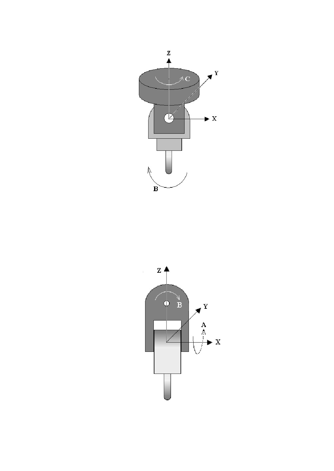
Figure 13-4 Double Swing Head C, B-axis Structure
5、Double Swing Head B, A-axis Structure, B-axis driving, A-axis
driven(structure code: 1BA0)
Tool rotates around X-axis(A-axis), A-axis rotates around Y-axis(B-axis), as the
following figure shown.
Figure 13-5 Double Swing Head B, A-axis Structure
185
13.3.2 Workbench Structure
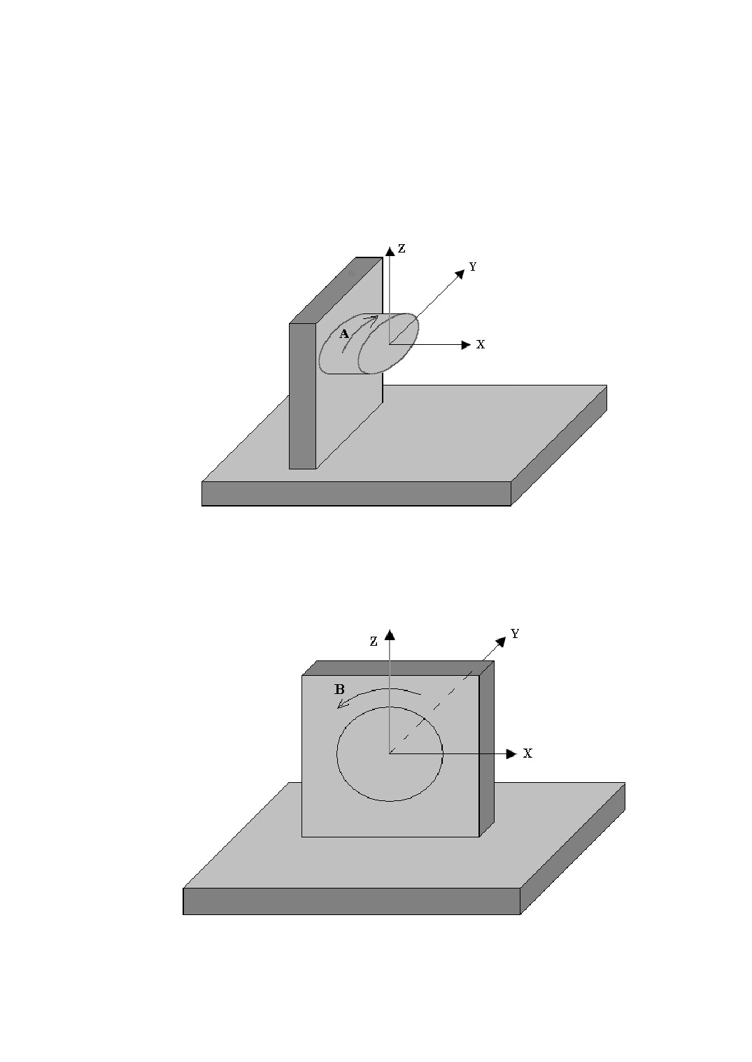
1、Single Turntable A-axis Structure(structure code: 20A0)
Workbench rotates around X-axis, as the following figure shown.
Figure 13-6 Single Turntable A-axis Structure
2、Single Turntable B-axis Structure(structure code: 20B0)
Workbench rotates around Y-axis, as the following figure shown.
Figure 13-7 Single Turntable B-axis Structure
186
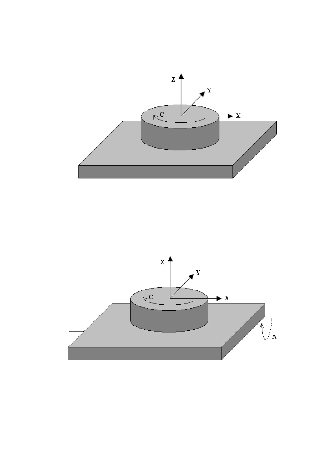
3、Single Turntable C-axis Structure(structure code: 20C0)
Workbench rotates around Z-axis, as the following figure shown.
Figure 13-8 Single Turntable C-axis Structure
4、Double Turntable A, C-axis Structure, A-axis driving, C-axis driven
(structure code: 2AC0)
Workbench rotates around Z-axis(C-axis), C-axis rotates around X-axis(A-axis), as
the following figure shown.
Figure 13-9 Double Turntable A, C-axis Structure
5、Double Turntable C, A-axis Structure, C-axis driving, A-axis driven
(structure code: 2CA0)
Workbench rotates around X-axis(A-axis), A-axis rotates around Z-axis(C-axis), as
the following figure shown.
187
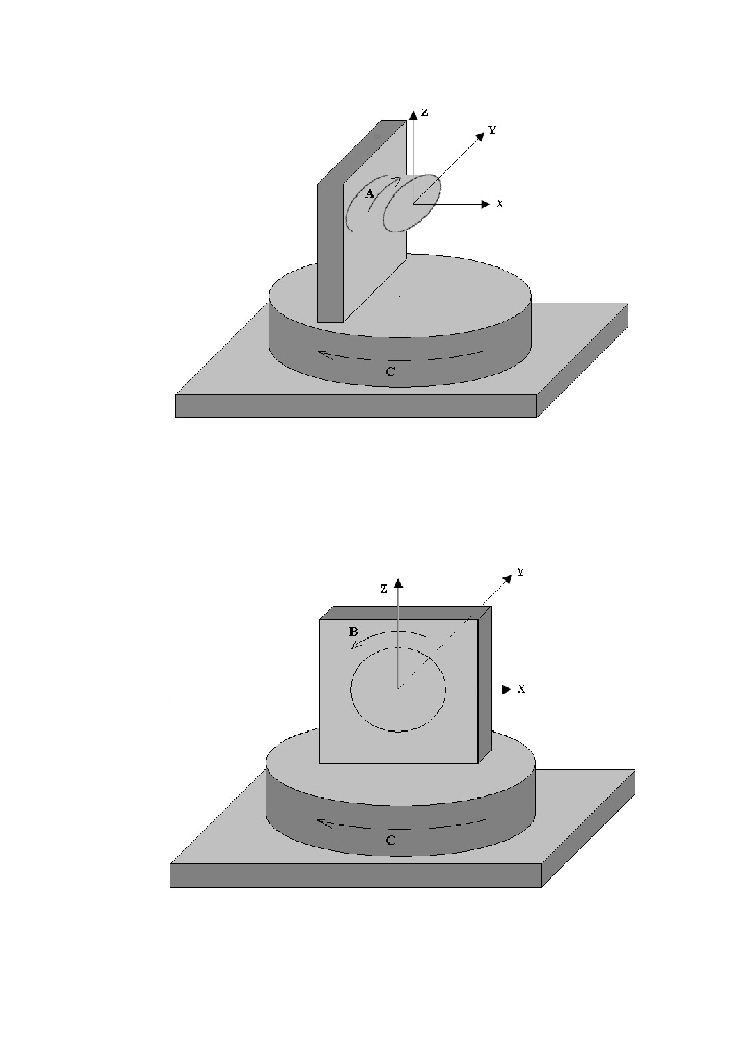
Figure 13-10 Double Turntable C, A-axis Structure
6、Double Turntable C, B-axis Structure, C-axis driving, B-axis driven
(structure code: 2CB0)
Workbench rotates around Y-axis(B-axis), B-axis rotates around Z-axis(C-axis), as
the following figure shown.
Figure 13-11 Double Turntable C, B-axis Structure
188
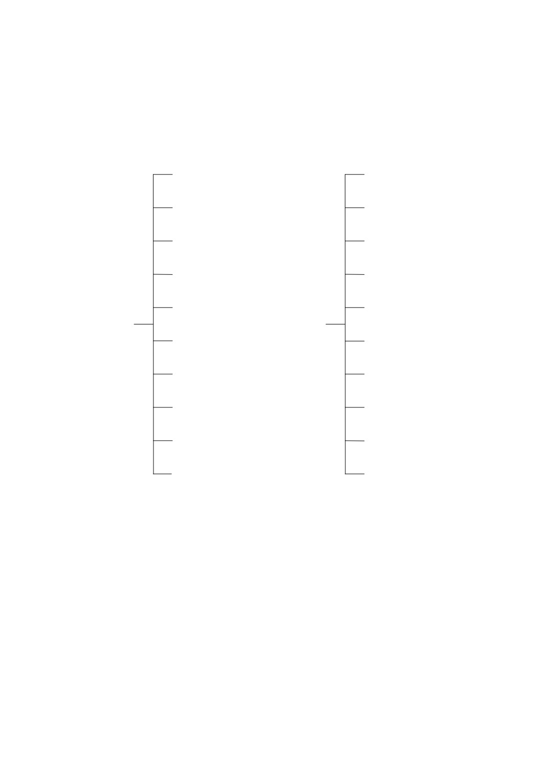
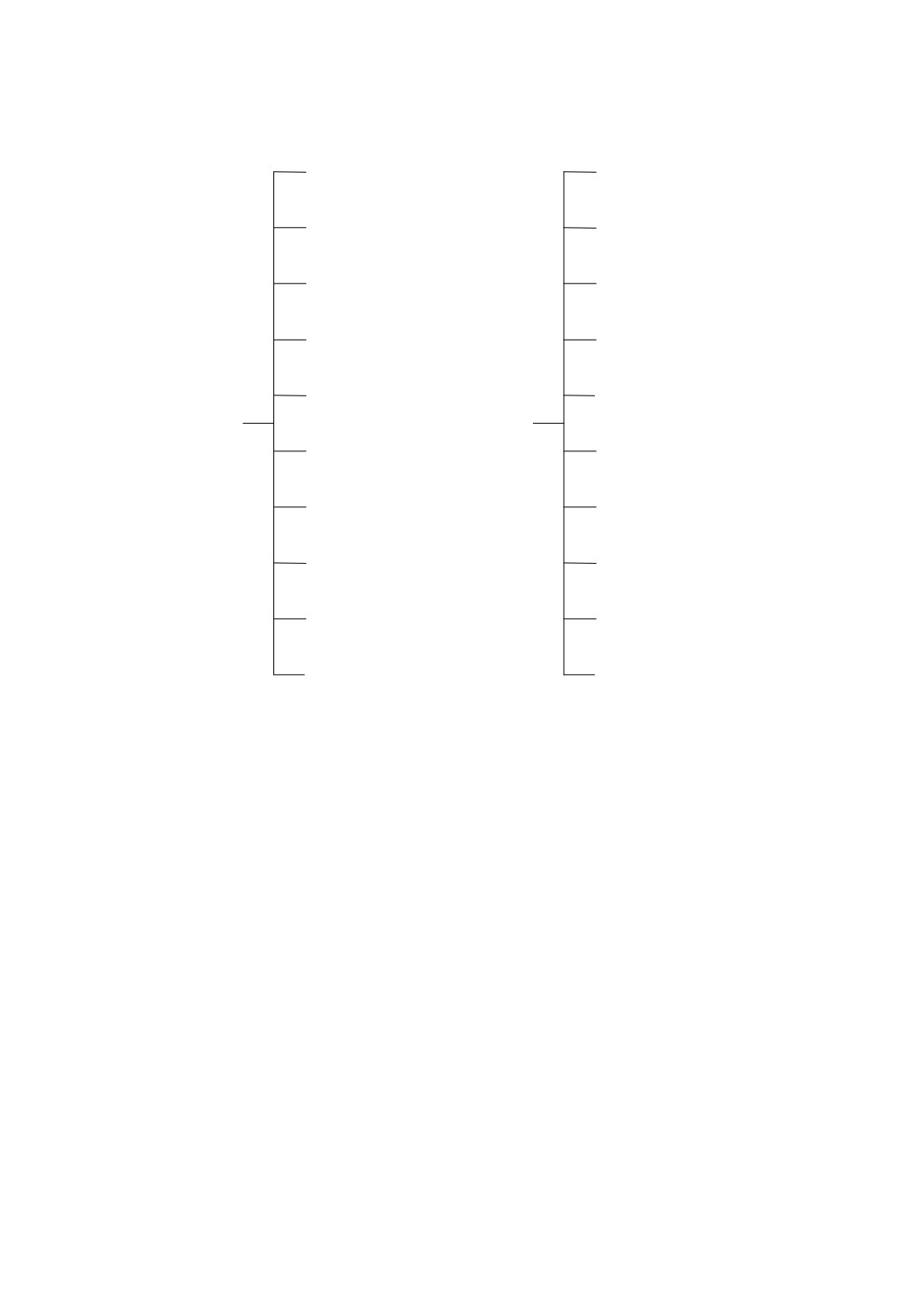
13.4 Appendix Four, Menu Tree Structure
PROG
(F1)
MNUL
(F1)
MDI
(F2)
TCS
(F2)
MAGT
(F3)
PSWD
(F3)
OFST
(F4)
VARI
(F4)
SCRD
(F5)
Main
Main
DNC
(F5)
Menu
Menu
REFC
(F6)
(1)
(2)
SSET
(F7)
TFED
(F7)
DIAG
(F8)
TEST
(F8)
VSWT
(F9)
STAT
(F9)
MNUR (F10)
Submenus Tree Structure of Main Menu (1)
189
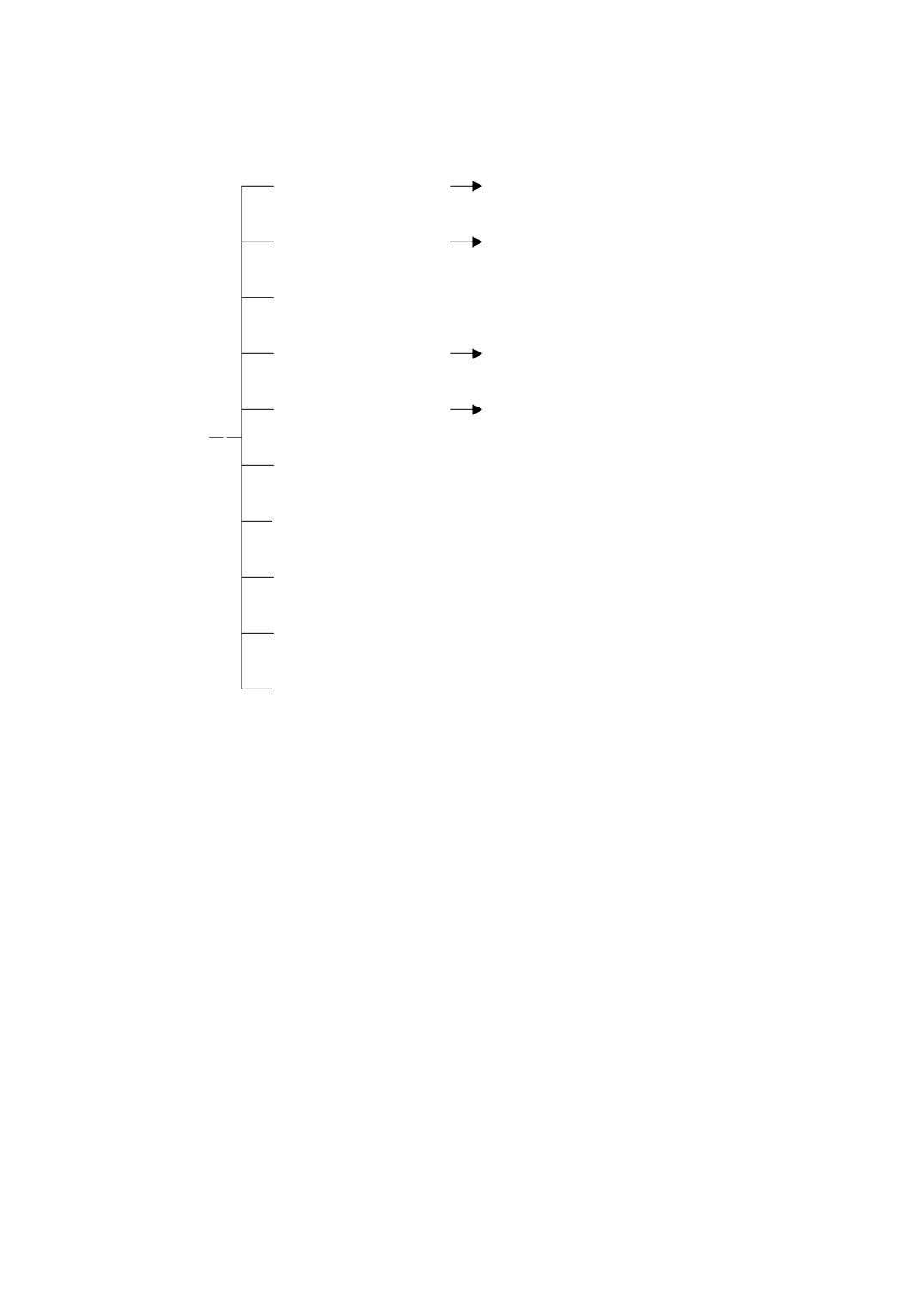
LDPG
(F1)
To load, select and sort a program
PEDT
(F2)
To edit a program
NFIL
(F3)
To delete, backup, rename, copy, sort a
PMAN
(F4)
program file
PBRK
(F5)
To do correlation operations of a
PROG
program breakpoint
(F1)
GTLN
(F6)
PVRF
(F7)
RRUN
(F8)
EXWK
(F9)
PGMR
(F10)
190
CCUR
(F1)
TCUR
(F1)
ADD
(F2)
DEC
(F3)
REC1
(F4)
REC2
(F5)
SCRD
OFST
(F5)
(F4)
MIDP
(F6)
DECP
(F7)
WRST
(F8)
RESM
(F9)
ORET
(F10)
CRET
(F10)
191
PARA
(F1)
PDIA
(F1)
CHNL
(F2)
LDEF
(F2)
PANL
(F3)
DTBL
(F3)
MCOD
(F4)
BREG
(F4)
ALME
(F5)
PMSG
(F5)
SSET
DIAG
(F7)
(F8)
SDIA
(F6)
REG
(F7)
ALRM
(F8)
AHIS
(F9)
SETR
(F10)
PLCR
(F10)
192

LMOV
(F1)
RMOV
(F2)
UMOV
(F3)
DMOV
(F4)
CLER
(F5)
VSWT
(F9)
ZMUP
(F6)
ZMDW
(F7)
ZORG
(F5)
VSWT
(F9)
GRET
(F10)
193
Submenus Tree Structure of Main Menu (2)
IPWD
(F1)
3PTS
(F1)
SPWD
(F2)
2VTR
(F2)
SPAN
(F3)
LGOF
(F4)
EULR
(F4)
TCS
PSWD
F2
F3
PWRT
(F10)
TCSR
(F10)
194
LVAR
(F1)
DNCR
(F1)
PVAR
(F2)
WONL
(F2)
SVAR
(F3)
VSCH
(F4)
DSET
(F5)
VARI
DNC
F4
F5
VRET
(F10)
RETD
(F10)
195
TFOP
(F1)
TTST
(F1)
TFCL
(F2)
MCHK
(F5)
TFED
TEST
F4
F5
TFRT
(F10)
TERT
(F10)
196

CHN
(F1)
ENG
(F2)
STAT
F9
STRT
(F10)
197

14 Operation Correcting Records
Version
Modification contents
Applicable
Number
Software
V1.0
V1.0
1) Add operation correcting records;
2) Add §3.1.1: program preview;
3)
§6.5: logic aixs configuration, add part configuration
items;
4)
§7.1.3.3: ladder diagram edit menu, add [PCPY],
[PPST] functions;
5) Update §7.3: PLC data table;
6) Add §7.5: B register;
V1.1
V1.1~
7)
§10.2 add two-way pitch compensation;
8)
§11.5: system softewware limits alarm, add a
condition of not detecting software limits;
9)
§12.1: system parameter definition, add parameter
items such as
7,
200~207,
290~297,
347,
348,
1111~1199,
1210~1217, 1220~1227,
2007,
2008,
and delete parameter item 2044;
10) Update §12.4: menu tree structure;
1) Modify §1.1.1: CNC system interface, main window
and first side window display coordinate system;
2)
§3.1: Loading a Machining program, add “network
program”;
3) Add §3.1.4: loading a network program;
4) Add §3.1.5: loading an extended program;
5)
§3.5: debugging a program, add handwheel
V1.2
V1.2~
debugging function;
6) Modify §3. 6: handwheel interruption;
7)
§4.1: classification of program file, add network
program;
8)
§4.2.1: opening a program file, add creating a new
extended program file;
9)
§4.3: managing a program file, add network program
198

moudle and adjust interface;
10) Add §5.5: speed curve display;
11) §6.3.2: workpiece coordinate system setting, add
“WRST”, “DECP” operation;
12) §6.6: M-code’s extension definition, add M-code
calling subroutine function;
13) Add §6.10: statistic information;
14) Modify §7.1.3.2: function command menu;
15) §7.1.3.3: ladder diagram edit menu, add “MASK”
function;
16) Add §7.6: PLC Message;
17) Add §10: measurement;
18) Add §10.1: tool measurement;
19) Add
§11.2: concrete examples in pitch error
compensation;
20) Add §11.4:circular arc across quadrant compensation;
21) Add §12.6: system alarm records query window;
22) Update
§13.1 appendix one
: system parameter
definition, add parameters
13,
17,
158,
161,
170~177,
187,
188,
189,
190,
194,
210~212,
215~217, 220~222, 227, 228, 408, 409, 421, 423,
424,
495,
2030,
2034,
2070~2077,
2080~2087,
3001~3008,
3051~3058; delete parameters
406,
1111~1119,
1121~1129,
1131~1139,
1141~1149,
1151~1159,
1161~1169,
1171~1179,
1181~1189,
1191~1199, 2001, 2002;
23) Update §13.2 appendix two: system alarm definition,
add system alarms 3, 18, 24, 160, delete system
alarm 150;
24) Update §13.4 appendix four: menu tree structure;
199