Wittenstein Components & Systems. Catalog 2012/2013 - page 40
 

  Index      Manuals     Wittenstein Components & Systems. Catalog 2012/2013


Search            copyright infringement  


Content      ..     38      39      40      41     ..


Wittenstein Components & Systems. Catalog 2012/2013 - page 40


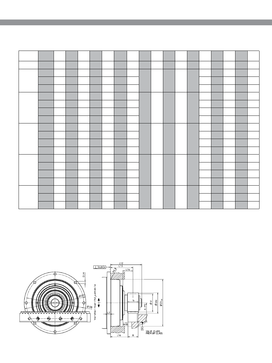
Precision

+

 System

z

A-PC 

± 0.3 

a)

b

B

d

a

d

x

D1

h7

D6

D7

D14

L7

L12

L13

L14

L15

L16

TP

+

 010 

(MA, MF)

2

20

44.0

26

24

48.3

42.441

0.4

90

109

118

5.5

7

71.0

50.5

20.5

8.5

38.5

TP

+

 025

(MA, MF)

2

20

44.0

26

24

48.3

42.441

0.4

110

135

145

5.5

8

73.5

53.0

24.0

12.0

41.0

2

40

64.4

26

24

89.2

84.883

0

73.5

53.0

24.0

12.0

41.0

3

20

59.0

31

29

72.3

63.662

0.4

76.0

52.5

23.5

9.0

38.0

TP

+

 050

(MA, MF)

2

40

64.4

26

24

89.2

84.883

0

140

168

179

6.6

10

87.0

66.5

28.5

16.5

54.5

3

20

59.0

31

29

72.3

63.662

0.4

89.5

66.0

28.0

13.5

51.5

3

34

80.1

31

29

114.5 108.226

0

90.5

66.0

28.0

13.5

51.5

4

20

78.2

41

39

94.8

84.882

0.2

97.0

67.5

29.5

10.0

48.0

TP

+

 110

(MA, MF)

3

34

80.1

31

29

114.5 108.226

0

200

233

247

9

12

106.0

81.5

31.5

17.0

67.0

4

20

78.2

41

39

94.8

84.882

0.2

112.5

83.0

33.0

13.5

63.5

4

30

98.7

41

39

135.6 127.324

0

112.5

83.0

33.0

13.5

63.5

5

19

86.4

51

49

115.1 100.798

0.4

120.0

85.0

35.0

10.5

60.5

TP

+

 300

(MA, MF)

4

30

98.7

41

39

135.6 127.324

0

255

280

300

13.5

18

131.5

102.0

36.0

16.5

82.5

5

19

86.4

51

49

115.1 100.798

0.4

139.0

104.0

38.0

13.5

79.5

5

30

113.6

51

49

169.4 159.155

0

135.0

104.0

38.0

13.5

79.5

6

19

105.9

61

59

138.0 120.958

0.4

142.5

106.0

40.0

10.5

76.5

TP

+

 500

(MA, MF)

5

30

113.6

51

49

169.4 159.155

0

285

310

330

13.5

20

147.5

116.5

41.5

17.0

92.0

6

19

105.9

61

59

138.0 120.958

0.4

155.0

118.5

43.5

14.0

89.0

6

28

132.1

61

59

190.5 178.254

0

154.0

118.5

43.5

14.0

89.0

TP System 
output 

Module

MA = HIGH ToRquE 
MF = Standard 

All dimensions in [mm]

a)

  please contact us for precise dimensions;  

align mechanism recommended (alignment  
dimension ± 0.3 mm)

Premium Class

+

 pinion 

on


TP system output

 with 

Premium Class rack

(all pinions, pressure angle 

a

=20°, inclination angle 

b

=19,5283° left-handed)

z  = Number of teeth
d

a

 = Tip diameter

d = Partial circle diameter 
x = Profile correction

Dimensions

332

alpha

Pr

ecision

+


System

z

F

2T 

[N] 

(lb

f

)

MF

i = 4

F

2T

[N] 

(lb

f

)

MA

i = 22

T

2B

[Nm] 

(in.lb)

MF

i = 4

T

2B


[Nm] 

(in.lb)

MA

i = 22

V

Max


[m/min] 

(in/sec.)

MF

i = 4

V

Max


[m/min]

(in/sec)

MA

i = 22

m

pinion

[kg] 

(lb

m

)

TP

+

 010

2

20

2400

2400

51

51

200

36

0.4

(540)

(540)

(452)

(452)

(132)

(24)

(0.9)

TP

+

 025

2

20

3400

3400

72

72

150

36

0.4

(765)

(765)

(638)

(638)

(99)

(24)

(0.9)

2

40

3400

3400

144

144

300

72

1.3

(765)

(765)

(1275)

(1275)

(197)

(48)

(2.9)

3

20

3400

3400

108

108

225

54

1.0

(765)

(765)

(956)

(956)

(148)

(36)

(2.3)

TP

+

 050

2

40

7100

7100

301

301

267

60

1.3

(1598)

(1598)

(2664)

(2664)

(176)

(40)

(2.9)

3

20

11100

11100

353

353

200

45

1.0

(2498)

(2498)

(3125)

(3125)

(132)

(30)

(2.3)

3

34

10800

10800

584

584

340

77

2.4

(2430)

(2430)

(5169)

(5169)

(224)

(51)

(5.4)

4

20

10800

10800

458

458

267

60

2.0

(2430)

(2430)

(4054)

(4054)

(176)

(40)

(4.5)

TP

+

 110

3

34

13000

13000

703

703

298

69

2.4

(2925)

(2925)

(6222)

(6222)

(196)

(46)

(5.3)

4

20

21000

21000

891

891

233

54

2.0

(4725)

(4725)

(7886)

(7886)

(153)

(36)

(4.5)

4

30

22000

22000

1401

1401

350

81

3.9

(4950)

(4950)

(12399)

(12399)

(230)

(54)

(8.7)

5

19

21000

21000

1058

1058

277

64

3.1

(4725)

(4725)

(9364)

(9364)

(182)

(42)

(6.9)

z

i = 20

i = 22

i = 20

i = 22

i = 20

 i = 22

TP

+

 300

4

30

22000

22000

1401

1401

70

54

3.9

(4950)

(4950)

(12399)

(12399)

(46)

(36)

(8.7)

5

19

31000

32000

1562

1646

55

43

3.1

(6975)

(7200)

(13824)

(14568)

(36)

(29)

(6.9)

5

30

30300

30800

2411

2501

88

68

10.4

(6818)

(6930)

(21338)

(22136)

(58)

(45)

(23)

6

19

30500

30800

1845

1901

67

51

5.8

(6863)

(6930)

(16329)

(16825)

(44)

(34)

(12.9)

TP

+

 500

5

30

34000

34000

2706

2706

88

68

10.4

(7650)

(7650)

(23949)

(23949)

(58)

(45)

(23)

6

19

41000

41600

2480

2570

67

51

5.8

(9225)

(9360)

(21948)

(22747)

(44)

(34)

(12.9)

6

28

41000

41000

3654

3654

98

76

14.5

(9225)

(9225)

(32338)

(32338)

(64)

(50)

(32.1)

Mechanical


systems


Rack & Pinion


system

Module

Module

TP

+

 gearhead 

with

 Premium Class

+

 pinion 

on

 TP system output 

with


Premium Class rack

Technical data for the smallest available ratio

Technical data based on 1000 load cycles per hour.
More combinations possible with cymex

®

F

2T

 = Max. moving force

T

2B

 = Max. acceleration torque

MA = HIGH ToRquE 
MF = Standard 

Technical data

Shock factor for rack moving force

Shock factor 

L

F

 [-]

Load cycles per hour Z

h

 [1/h]

In Z-axis without a balancing weight additional load 
changes can be caused due to additional move-
ments in other axes. 

Calculation including shock factor:
F

2t

 * L

F

 F

2t, LF

 F

2T

333

Precision/Smart System

z

A-PC 

± 0,3 

b)

A-SC 

± 0,3 

b)

b

B

d

a

d

x

D5

h7

D6

D7

D14

L4

L5

L7

L12

L16

TP

+

/TK

+

 004

2

26

50.4

41.9

26

24

60.7

55.173

0.4

64

79

86

4.5

19.5

8

4

7.2

20.5

TP

+

/TK

+

/

TPK

+

 010

2

29 

a)

53.4

44.9

26

24

66.6

61.539

0.3

90

109

118

5.5

40

11

7

8.3

41

2

33

57.6

49.1

26

24

75.1

70.028

0.3

90

109

118

5.5

30

11

7

8.3

31

2

37

61.9

53.4

26

24

83.6

78.516

0.3

90

109

118

5.5

30

11

7

8.3

31

TP

+

/TK

+

/

TPK

+

 025

2

35 

a)

59.7

51.2

26

24

79.4

74.272

0.3

110

135

145

5.5

39

10

8

8.6

40

2

40 

c)

65.0

56.5

26

24

90.0

84.882

0.3

110

135

145

5.5

29

10

8

8.6

30

2

45

70.2

61.7

26

24

100.2

95.493

0.22

110

135

145

5.5

29

10

8

8.6

30

TP

+

/TK

+

/

TPK

+

 050

3

31

a)

76.2

66.7

31

29

106.4

98.676

0.3

140

168

179

6.6

51

14.5

10

11.3

52

3

35 

c)

82.6

73.1

31

29

119.1 111.409

0.3

140

168

179

6.6

38

14.5

10

11.3

39

3

40 

c)

90.6

81.1

31

29

135.0 127.324

0.3

140

168

179

6.6

38

14.5

10

11.3

39

TP

+

/TK

+

/

TPK

+

 110

4

38

116.6

105.6

41

39

171.3 161.277

0.25

200

233

247

9

50

17.5

12

14.5

51

4

40 

d)

119.9

108.9

41

39

177.9 169.766

0

200

233

247

9

50

17.5

12

14.5

51

TP

+

 300

5

32 

a) c)

120.3

51

49

182.6 169.766 0.285

255

280

300

13.5

91

20

18

20

92

TP

+

 500

6

31 

a)

143.4

61

59

212.8 197.352 0.295

285

310

330

13.5

110

20

20

20

111

Premium Class RTP pinion 

on

 TP output 

with


Premium 

and

 Smart Class rack

(all pinions, pressure angle 

a

=20°, inclination angle 

b

=19,5283° left-handed)

z = Number of teeth
d

a

 = Tip diameter

d = Partial circle diameter
x   = Profile correction

All dimensions in [mm]

a)

 with adapter flange

b)

  please contact us for precise dimensions;  

align mechanism recommended (alignment dimension ± 0.3 mm)

c)

 also in combination with TP

+

 HIGH ToRquE

d)

 only in combination with TP

+

 HIGH ToRquE

Dimensions

TP output 

Module

334

alpha

Pr

ecision System

Smart System

z

F

2T 

[N] 

(lb

f

)

MF

i = 4
(PC)

F

2T


[N] 

(lb

f

)

MF

i = 4
(SC)

F

2T


[N]

(lb

f

)

MA

i = 22

(PC)

F

2T 

[N]

(lb

f

)

MA

i = 22

(SC)

T

2B


[Nm]

(in.lb)

MF

i = 4
(PC)

T

2B 

[Nm]

(in.lb)

MF

i = 4
(SC)

T

2B


[Nm]

(in.lb)

MA

i = 22

(PC)

T

2B 

[Nm]

(in.lb)

MA

i = 22

(SC)

V

Max

[m/min] 

(in/sec)

MF

 i = 4

V

Max

[m/min]

(in/sec)

MA 

i = 22

m

pinion

[kg]

(lb

m

)

TP

+

 004 

2

26

1400

1400

39

39

255

0.41

(315)

(315)

(346)

(346)

(168)

(0.91)

TP

+

 010 

2

29

2300

2300

71

71

290

0.45

(518)

(518)

(629)

(629)

(191)

(1)

2

33

2550

2550

89

89

330

0.60

(574)

(574)

(788)

(788)

(217)

(1.33)

2

37

2500

2500

98

98

370

0.80

(563)

(563)

(868)

(868)

(243)

(1.77)

TP

+

 025

2

35

3400

3400

126

126

260

0.62

(765)

(765)

(1116)

(1116)

(171)

(1.38)

2

40 

a)

3700

3700

3700

3700

157

157

157

157

300

72

0.85

(833)

(833)

(833)

(833)

(1390)

(1390)

(1390)

(1390)

(197)

(48)

(1.88)

2

45

3600

3600

172

172

335

1.15

(810)

(810)

(1523)

(1523)

(220)

(2.55)

TP

+

 050

3

31

10800

9000

533

444

310

1.40

(24230)

(2025)

(4718)

(3930)

(204)

(3.1)

3

35

 a)

12000

9000

12000

9000

668

501

668

501

340

78

1.77

(2700)

(2025)

(2700)

(2025)

(5912)

(4434)

(5912)

(4434)

(224)

(52)

(3.92)

3

40

 a)

12000

9000

12000

9000

764

573

764

573

390

90

2.50

(2700)

(2025)

(2700)

(2025)

(6762)

(5072)

(6762)

(5072)

(256)

(60)

(5.53)

TP

+

 110

4

38

22000

16000

1774

1290

440

5.55

(4950)

(3600)

(15700)

(11417)

(289)

(12.27)

4

40

 b)

22000

16000

1867

1358

108

5.24

(4950)

(3600)

(16523)

(12019)

(71)

(11.59)

z

i = 20

i = 22

i = 20

i = 22

i = 20

i = 22

TP

+

 300

5

32

 a)

28300

28300

2402

2402

_

93

72

6.47

(6368)

(6368)

(21258)

(21258)

(61)

(48)

(14.30)

TP

+

 500

6

31

36400

3592

108

12.3

(8190)

(31790)

(71)

(27.19)

Mechanical


systems


Rack & Pinion


system

Module

Module

TP

+

 gearhead 

with

 Premium Class RTP pinion 

on

 TP output 

with


Premium  

and

 Smart Class rack 

· Technical data for the smallest available ratio

F

2T

 = Max. moving force

T

2B 

= Max. acceleration torque

SC = Smart Class
PC = Premium Class

a)

 also in combination with TP

+

 HIGH ToRquE

d)

 only in combination with TP

+

 HIGH ToRquE

Technical data based on 1000 load cycles per hour.
More combinations possible with cymex

®

MA = HIGH ToRquE 
MF = Standard 

Technical data

Shock factor for rack moving force

Shock factor 

L

F

 [-]

Load cycles per hour Z

h

 [1/h]

In Z-axis without a balancing weight additional load 
changes can be caused due to additional move-
ments in other axes. 

Calculation including shock factor:
F

2t

 * L

F

 = F

2t, LF

 F

2T

335

Precision/Smart System

z

A-PC 

± 0,3

a)

A-SC 

± 0,3

a)

b

B

d

a

d

x

D1

g6

D4

D5

L3

L4

L11

± 1

L12

L13

L14

L15

L16

SP

+

 075

2

20

44.0

35.5

26

24

48.3

42.441

0.4

70

6.6

85

20

7

76

61.0

40.5

20.5

8.5

28.5

SP

+

 100

2

20

44.0

35.5

26

24

48.3

42.441

0.4

90

9

120

30

10

101

71.5

51.0

21.0

9

39

2

40

64.4

55.9

26

24

89.2

84.883

0

71.0

51.0

21.0

9

39

3

20

59.0

49.5

31

29

72.3

63.662

0.4

73.5

54.0

24.0

9.5

39.5

SP

+

 140

2

40

64.4

55.9

26

24

89.2

84.883

0

130

11

165

30

12

141

75.0

54.5

24.5

12.5

42.5

3

20

59.0

49.5

31

29

72.3

63.662

0.4

77.5

54.0

24.0

9.5

39.5

3

34

80.1

70.6

31

29

114.5 108.226

0

77.0

54.0

24.0

9.5

39.5

4

20

78.2

67.2

41

39

94.8

84.882

0.2

83.5

59.0

29.0

9.5

39.5

SP

+

 180

3

34

80.1

70.6

31

29

114.5 108.226

0

160

13.5

215

30

15

182

82.0

57.5

27.5

13

43

4

20

78.2

67.2

41

39

94.8

84.882

0.2

88.5

59.0

29.0

9.5

39.5

4

30

98.7

87.7

41

39

135.6 127.324

0

87.0

59.0

29.0

9.5

39.5

5

19

86.4

51

49

115.1 100.798

0.4

94.5

64.5

34.5

10

40

SP

+

 210

4

30

98.7

87.7

41

39

135.6 127.324

0

180

17

250

38

17

215

99.9

70.4

32.5

13

50.9

5

19

86.4

51

49

115.1 100.798

0.4

107.4

72.4

34.5

10

47.9

5

30

113.6

51

49

169.4 159.155

0

105.9

72.4

34.5

10

47.9

6

19

105.9

61

59

138.0 120.958

0.4

113.4

77.9

40.0

10.5

48.4

SP

+

 240

5

30

113.6

51

49

169.4 159.155

0

200

17

290

40

20

242

109.9

78.9

39.0

14.5

54.4

6

19

105.9

61

59

138.0 120.958

0.4

120.9

80.9

41.0

11.5

51.4

6

28

132.1

_

61

59

190.5 178.254

0

119.9

80.9

41.0

11.5

51.4

SP system 
output  

Module

z = Number of teeth
d

a

 = Tip diameter

d = Partial circle diameter 
x = Profile correction

Premium Class

+

 pinion 

on


SP

+

 System output 

with 

Premium 

and

 Smart Class rack

(all pinions, pressure angle 

a

=20°, inclination angle 

b

=19,5283° left-handed)

All dimensions in [mm]

a)

  please contact us for precise dimensions;  

align mechanism recommended (alignment dimension ± 0.3 mm)

Dimensions

336

alpha

Pr

ecision System

Smart System

z

F

2T 

[N]

(lb

f

)

i = 4
(PC)

F

2T 

[N]

(lb

f

)

i = 4
(SC)

F

2T 

[N]

(lb

f

)

i = 16

(PC)

F

2T 

[N]

(lb

f

)

i = 16

(SC)

T

2B 

[Nm]

(in.lb)

i = 4
(PC)

T

2B 

[Nm]

(in.lb)

i = 4
(SC)

T

2B 

[Nm]

(in.lb)
i = 16

(PC)

T

2B 

[Nm]

(in.lb)
i = 16

(SC)

V

Max


[m/min]

(in/sec)

i = 4

V

Max


[m/min]

(in/sec)  

i = 16

m

pinion

[kg]

(lb

m

)

SP

+

 075

2

20

3300

3300

3300

3300

68

68

68

68

200

50

0.4

(743)

(743)

(743)

(743)

(602)

(602)

(602)

(602)

(132)

(33)

(0.89)

SP

+

 100

2

20

6400

5000

6400

5000

136

106

136

106

150

37

0.4

(1440)

(1125)

(1440)

(1125)

(1204)

(939)

(1204)

(939)

(99)

(25)

(0.89)

2

40

6100

5000

6100

5000

259

212

259

212

300

75

1.3

(1373)

(1125)

(1373)

(1125)

(2293)

(1877)

(2293)

(1877)

(197)

(50)

(2.88)

3

20

6000

6000

6000

6000

191

191

191

191

225

56

1.0

(1350)

(1350)

(1350)

(1350)

(1691)

(1691)

(1691)

(1691)

(148)

(37)

(2.21)

SP

+

 140

2

40

7100

5000

7100

5000

301

212

301

212

266

66

1.3

(1598)

(1125)

(1598)

(1125)

(2664)

(1877)

(2664)

(1877)

(175)

(44)

(2.88)

3

20

10000

9000

10000

9000

318

286

318

286

200

50

1.0

(2250)

(2025)

(2250)

(2025)

(2815)

(2532)

(2815)

(2532)

(132)

(33)

(2.21)

3

34

9800

9000

9800

9000

530

487

530

487

340

85

2.4

(2205)

(2025)

(2205)

(2025)

(4691)

(4310)

(4691)

(4310)

(224)

(56)

(5.31)

4

20

9400

9400

9400

9400

399

399

399

399

266

66

2.0

(2115)

(2115)

(2115)

(2115)

(3532)

(3532)

(3532)

(3532)

(175)

(44)

(4.42)

SP

+

 180

3

34

13600

9000

13600

9000

736

487

736

487

297

85

2.4

(3060)

(2025)

(3060)

(2025)

(6514)

(4310)

(6514)

(4310)

(195)

(56)

(5.31)

4

20

13600

13600

13600

13600

577

577

577

577

233

66

2.0

(3060)

(3060)

(3060)

(3060)

(5107)

(5107)

(5107)

(5107)

(153)

(44)

(4.42)

4

30

13200

13200

13200

13200

840

840

840

840

350

100

3.9

(2970)

(2970)

(2970)

(2970)

(7434)

(7434)

(7434)

(7434)

(230)

(66)

(8.62)

5

19

12800

12800

645

645

277

78

3.1

(2880)

(2880)

(5709)

(5709)

(182)

(52)

(6.86)

SP

+

 210

4

30

21700

16000

21700

16000

1381

1019

1381

1019

250

87

2.0

(4883)

(3600)

(4883)

(3600)

(1222)

(9019)

(12222)

(9019)

(164)

(58)

(4.42)

5

19

21800

21800

1099

1099

197

69

3.9

(4905)

(4905)

(9727)

(9727)

(130)

(46)

(8.62)

5

30

21000

21000

1671

1671

312

109

3.1

(4725)

(4725)

(14789)

(14789)

(205)

(72)

(6.86)

6

19

20600

20600

1246

1246

237

83

10.4

(4635)

(4635)

(11028)

(11028)

(156)

(55)

(22.99)

SP

+

 240

5

30

31700

31700

2523

2523

275

109

10.4

(7133)

(7133)

(22329)

(22329)

(181)

(72)

(22.99)

6

19

32000

32000

1935

1935

209

83

5.8

(7200)

(7200)

(17125)

(17125)

(138)

(55)

(12.82)

6

28

31000

31000

2763

2763

308

122

14.5

(697)

(6975)

(24453)

(24453)

(203)

(81)

(32.05)

Mechanical


systems


Rack & Pinion


system

Module

SP

+

 gearhead 

with

 Premium

+

 pinion on SP

+

 system output 

with


Premium and Smart Class 

rack 

· Technical data for the smallest available ratio

F

2T

 = Max. moving force

T

2B

 = Max. acceleration torque

Technical data based on 1000 load cycles per hour.
More combinations possible with cymex

®

Technical data

Shock factor for rack moving force

Shock factor 

L

F

 [-]

Load cycles per hour Z

h


[1/h]

In Z-axis without a balancing weight additional load 
changes can be caused due to additional move-
ments in other axes. 

Calculation including shock factor:
F

2t

 * L

F

 = F

2t, LF

 F

2T

337

Economy

+

/Smart System

z

A-VC 

± 0.3 

a)

A-SC 

± 0.3 

a)

b

B

d

a

d

x

D1

g6

D4

D5

L3

L4

L11 

± 1

L12

L16

L23

SP

+

SK

+

 060

2

15

38.9

30.4

26

24

37.8

31.831

0.5

60

5.5

68

20

6

62

2

27

32

2

16

40.0

31.5

26

24

40.0

33.953

0.5

60

5.5

68

20

6

62

2

27

32

2

18

41.9

33.4

26

24

43.8

38.197

0.4

60

5.5

68

20

6

62

2

27

32

SP

+

/SK

+

SPK

+

 075 

VDS 050

2

18

41.9

33.4

26

24

43.8

38.197

0.4

70

6.6

85

20

7

76

2.5

28

33

2

20

44.0

35.5

26

24

48.1

42.441

0.4

70

6.6

85

20

7

76

2.5

28

33

2

22

46.1

37.6

26

24

52.3

46.686

0.4

70

6.6

85

20

7

76

2.5

28

33

SP

+

/SK

+

SPK

+

 100 

VDS 063

2

23

47.2

38.7

26

24

54.4

48.808

0.4

90

9

120

30

10

101

3

39

34

2

25

49.3

40.8

26

24

58.6

53.052

0.4

90

9

120

30

10

101

3

39

34

2

27

51.2

42.7

26

24

62.5

57.296

0.3

90

9

120

30

10

101

3

39

34

SP

+

/SK

+

SPK

+

 140 

VDS 080

3

20

59.0

49.5

31

29

71.7

63.662

0.4

130

11

165

30

12

141

3

51

51

3

22

62.2

52.7

31

29

78.3

70.028

0.4

130

11

165

30

12

141

3

51

51

3

24

65.4

55.9

31

29

84.7

76.394

0.4

130

11

165

30

12

141

3

51

51

SP

+

/SK

+

SPK

+

 180 

VDS 100

4

20

79.0

68.0

41

39

96.1

84.883

0.4

160

13.5

215

30

15

182

3

44

54

SP

+

 210

4

25

89.4

78.4

41

39

116.8 106.103

0.34

180

17

250

38

17

215

3

63

65

SP

+

 240

5

24

99.4

51

49

140.8 127.324

0.35

200

17

290

40

20

242

3

63

73

Standard Class RSP pinion 

with


SP involute output


with


Value 

and

 Smart Class rack 

(all pinions, pressure angle 

a

=20°, inclination angle 

b

=19,5283° left-handed) 

Output 
with SP 
involute 
toothing 
DIN5480 

Module

z = Number of teeth
d

a

 = Tip diameter

d = Partial circle diameter 
x = Profile correction

All dimensions in [mm]

a)

  please contact us for precise dimensions;  

align mechanism recommended (alignment dimension ± 0.3 mm)

Dimensions

338

alpha

Smart System

Economy

+

 System

z

F

2T 

[N]

(lb

f

)

i = 3
(VC)

F

2T 

[N]

(lb

f

)

i = 3
(SC)

F

2T


[N]

(lb

f

)

i = 16

(VC)

F

2T 

[N]

(lb

f

)

i = 16

(SC)

T

2B 

[Nm]

(in.lb)

i = 3
(VC)

T

2B 

[Nm]

(in.lb)

i = 3
(SC)

T

2B 

[Nm

(in.lb)]

i = 16

(VC)

T

2B 

[Nm]

(in.lb)
i = 16

(SC)

V

Max

[m/min]

(in/sec)

i = 3

V

Max

[m/min] 

(in/sec)

i = 16

m

pinion

[kg]

(lb

m

)

SP

+

 060 

2

15

1800

1800

2300

2300

29

29

37

37

200

37

0.18

(405)

(405)

(518)

(518)

(257)

(257)

(328)

(328)

(132)

(25)

(0.4)

2

16

1700

1700

2300

2300

29

29

39

39

210

40

0.19

(383)

(383)

(518)

(518)

(257)

(257)

(346)

(346)

(138)

(27)

(0.42)

2

18

1500

1500

2300

2300

29

29

44

44

240

45

0.23

(338)

(338)

(518)

(518)

(257)

(257)

(390)

(390)

(158)

(30)

(0.51)

SP

+

 075 

2

18

3300

3300

3300

3300

63

63

63

63

240

45

0.20

(743)

(743)

(743)

(743)

(558)

(558)

(558)

(558)

(158)

(30)

(0.45)

2

20

3300

3300

3300

3300

70

70

70

70

260

50

0.26

(743)

(743)

(743)

(743)

(620)

(620)

(620)

(620)

(171)

(33)

(0.58)

2

22

3300

3300

3300

3300

77

77

77

77

290

55

0.32

(743)

(743)

(743)

(743)

(682)

(682)

(682)

(682)

(191)

(37)

(0.71)

SP

+

 100

2

23

4300

5000

4300

5000

105

122

105

122

230

43

0.29

(968)

(1125)

(968)

(1125)

(930)

(1080)

(930)

(1080)

(151)

(29)

(0.65)

2

25

4300

5000

4300

5000

114

133

114

133

250

47

0.31

(968)

(1125)

(968)

(1125)

(1009)

(1178)

(1009)

(1178)

(164)

(31)

(0.69)

2

27

4300

5000

4300

5000

123

143

123

143

270

51

0.46

(968)

(1125)

(968)

(1125)

(1089)

(1266)

(1089)

(1266)

(178)

(34)

(1.02)

SP

+

 140

3

20

8000

9000

8000

9000

255

286

255

286

260

50

0.72

(1800)

(2025)

(1800)

(2025)

(2257)

(2532)

(2257)

(2532)

(171)

(33)

(1.60)

3

22

8000

9000

8000

9000

280

315

280

315

290

55

0.98

(1800)

(2025)

(1800)

(2025)

(2478)

(2788)

(2478)

(2788)

(191)

(37)

(2.17)

3

24

8000

9000

8000

9000

306

344

306

344

320

60

1.26

(1800)

(2025)

(1800)

(2025)

(2709)

(3045)

(2709)

(3045)

(210)

(40)

(2.79)

SP

+

 180

4

20

13000

13000

13000

13000

552

552

552

552

310

66

1.38

(2925)

(2925)

(2925)

(2925)

(4886)

(4886)

(4886)

(4886)

(204)

(44)

(3.05)

SP

+

 210

4

25

14000

16000

14000

16000

743

849

743

849

270

72

2.24

(3150)

(3600)

(3150)

(3600)

(6576)

(7514)

(6576)

(7514)

(178)

(48)

(4.96)

SP

+

 240

5

24

22000

22000

1401

1401

290

87

3.96

(4950)

(4950)

(12399)

(12399)

(191)

(58)

(8.76)

Mechanical


systems


Rack & Pinion


system

Module

SP

+

 gearhead 

with

 Standard Class RSP pinion 

on

 SP involute output 

with


Value  

and

 Smart Class rack 

· Technical data for the smallest available ratio

Technical data

F

2T

 = Max. moving force

T

2B

 = Max. acceleration torque 

SC = Smart Class
VC = Value Class

Technical data based on 1000 load cycles per hour.
More combinations possible with cymex

®

Shock factor for rack moving force

Shock factor 

L

F

 [-]

Load cycles per hour Z

h


[1/h]

In Z-axis without a balancing weight additional load 
changes can be caused due to additional move-
ments in other axes. 

Calculation including shock factor:
F

2t

 * L

F

 = F

2t, LF

 < F

2T

339


Content      ..     38      39      40      41     ..