Wittenstein Components & Systems. Catalog 2012/2013 - page 41
 

  Index      Manuals     Wittenstein Components & Systems. Catalog 2012/2013


Search            copyright infringement  


Content      ..     39      40      41      42     ..


Wittenstein Components & Systems. Catalog 2012/2013 - page 41


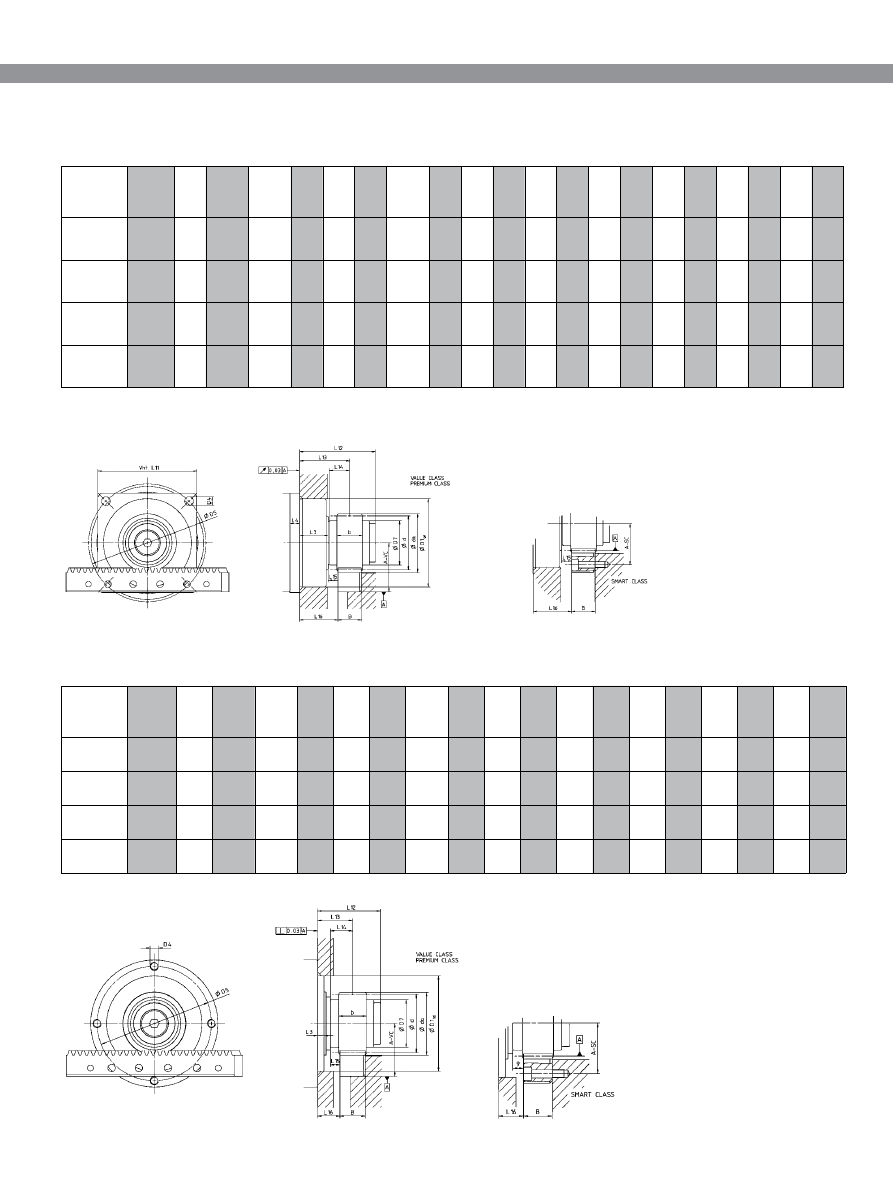
Economy/Smart System

z

A-VC 

± 0.3 

a)

A-SC 

± 0.3 

a)

b

B

d

a

d

x

D1

g6

D4

D5

D7

L3

L4

L11 L12 L13 L14 L15 L16

SP

+

/SK

+


060

2

18

41.9

33.4

26

24

43.7

38.197

0.4

60

5.5

68

0

20

6

62

54

39

19

7

27

SP

+

/SK

+

SPK

+

 075

VDS 050

2

22

45.7

37.2

26

24

51.4

46.686

0.2

70

6.6

85

40

20

7

76

62

40

20

8

28

SP

+

/SK

+

SPK

+

 100

VDS 063

2

26

49.6

41.1

26

24

59.1

55.174

0

90

9

120

45

30

10

101

95.5

51

21

9

39

SP

+

/SK

+

SPK

+

 140

VDS 080

3

24

64.2

54.7

31

29

82.3

76.395

0

130

11

165

58

30

12

141

122

65.5

35.5

21

51

z

A-VC 

± 0.3 

a)

A-SC 

± 0.3 

a)

b

B

d

a

d

x

D1

h6

D4

D5

D7

L3

L12

L13

L14

L15

L16

LP

+

/LK

+

/

LPK

+

 070

2

18

41.9

33.4

26

24

43.7

38.197

0.4

52

M5

62

0

5

42

27

19

7

15

LP

+

/LK

+

/

LPK

+

 090

2

22

45.7

37.2

26

24

51.4

46.686

0.2

68

M6

80

40

5

52

30

20

8

18

LP

+

/LK

+

/

LPK

+

 120

2

26

49.6

41.1

26

24

59.1

55.174

0

90

M8

108

45

6

77.5

33

21

9

21

LP

+

/LK

+

/

LPK

+

 155

3

24

64.2

54.7

31

29

82.3

76.395

0

120

M10

140

58

8

107

50.5

35.5

21

36

Key output  Module

z = Number of teeth
d

a

 = Tip diameter

d = Partial circle diameter
x = Profile correction

All dimensions in [mm]

a)

  please contact us for precise dimensions;  

align mechanism recommended (alignment dimension ± 0.3 mm)

Key output Module

Value Class pinion

 (shrunk/bonded) on 

shaft key

 with 

Value 

and

 Smart Class rack 

(all pinions, pressure angle 

a

=20°, inclination angle 

b

 = 19,5283° left-handed) 

z = Number of teeth
d

a

 = Tip diameter

d =Partial circle diameter 
x = Profile correction

All dimensions in [mm]

a)

  please contact us for precise dimensions;  

align mechanism recommended (alignment  
dimension ± 0.3 mm)

Dimensions

Value Class pinion

 (shrunk/bonded) on 

shaft key

 with 

Value 

and

 Smart Class rack 

(all pinions, pressure angle 

a

=20°, inclination angle 

b

=19,5283° left-handed) 

340

alpha

Economy System

Smart System

z

F

2T


[N]

(lb

f

)

(VC)

F

2T


[N]

(lb

f

(SC)

T

2B 

[Nm]

(in.lb)

(VC)

T

2B 

[Nm]

(in.lb)

(SC)

F

2T Not

[N]

(lb

f

)

T

2 Not

[Nm]

(lb

f

)

V

Max


[m/min]

(in/sec)

 i = 5

V

Max


[m/min]

(in/sec)

 i = 25

m

pinion

[kg]

(lb

m

)

SP

+

 060 

3

2

18

1550

1550

30

30

3000

57

0.3

(338)

(349)

(266)

(266)

(675)

(505)

(0.67)

10, 100

2

18

1650

1650

32

32

3000

57

0.3

(372)

(372)

(284)

(284)

(675)

(505)

(0.67)

4–7 / 16–70

2

18

2000

2000

38

38

3000

57

144

29

0.3

(450)

(450)

(337)

(337)

(675)

(505)

(95)

(20)

(0.67)

SP

+

 075 

All

2

22

3500

3500

82

82

5000

117

176

35

0.4

(788)

(788)

(726)

(726)

(1125)

(1036)

(116)

(23)

(0.89)

SP

+

 100

All

2

26

4300

5000

119

138

8500

234

156

31

0.6

(968)

(1125)

(1054)

(1222)

(1913)

(2071)

(103)

(21)

(1.33)

SP

+

 140

All

3

24

8000

9000

306

344

16000

611

192

38

1.6

(1800)

(2025)

(2709)

(3045)

(3600)

(5408)

(126)

(25)

(3.54)

z

F

2T 

[N]

(lb

f

)

(VC)

F

2T 

[N]

(lb

f

)

(SC)

T

2B 

[Nm]

(in.lb)

(VC)

T

2B


[Nm]

(in.lb)

(SC)

F

2T Not

[N]

(lb

f

)

T

2 Not

[Nm]

(lb

f

)

V

Max


[m/min]

(in/sec)

 i = 5

V

Max


[m/min]

(in/sec)

 i = 25

m

pinion

[kg]

(lb

m

)

LP

+

 070 

3, 10, 15, 

30, 100

2

18

1700

1700

32

32

2700

52

0.3

(383)

(383)

(284)

(284)

(608)

(461)

(0.67)

5, 7, 25, 50

2

18

1850

1850

35

35

2700

52

144

29

0.3

(417)

(417)

(310)

(310)

(608)

(461)

(95)

(20)

(0.67)

LP

+

 090

3, 10, 15, 

30, 100

2

22

3400

3400

79

79

4800

112

0.4

(765)

(765)

(700)

(700)

(1080)

(992)

(0.89)

5, 7, 25, 50

2

22

3500

3500

82

82

4800

112

176

35

0.4

(788)

(788)

(726)

(726)

(1080)

(992)

(116)

(23)

(0.89)

LP

+

 120 

All

2

26

4100

4500

113

124

7800

215

156

31

0.6

(923)

(1013)

(1001)

(1098)

(1755)

(1903)

(103)

(21)

(1.33)

LP

+

 155

All

3

24

6500

7000

248

267

14000

535

192

38

1.6

(1463)

(1575)

(2195)

(2363)

(3150)

(4735)

(126)

(25)

(3.54)

Mechanical


systems


Rack & Pinion


system

Ratio

Module

F

2T

 = Max. moving force

T

2B

 = Max. acceleration torque 

SC = Smart Class
VC = Value Class

Technical data based on 1000 load cycles per hour.
More combinations possible with cymex

®

Ratio

Module

F

2T

 = Max. moving force

T

2B

 = Max. acceleration torque 

SC = Smart Class
VC = Value Class

Technical data based on 1000 load cycles per hour.
More combinations possible with cymex

®

LP

+

 gearhead 

with

 Value Class pinion 

on 

shaft key

 with 

Value 

and

 Smart Class rack 

Technical data

Shock factor for rack moving force

Shock factor 

L

F

 [-]

Load cycles per hour Z

h

 [1/h]

Shock factor for rack moving force

Shock factor


L

F

 [-]

Load cycles per hour Z

h

 [1/h]

SP

+

 gearhead 

with

 Value Class pinion 

on 

shaft key

 with 

Value 

and

 Smart Class rack 

In Z -axis without a balancing weight additional 
load changes can be caused due to additional 
movements in other axes. 

Calculation including shock factor:
F

2t

 * L

F

 = F

2t, LF

 < F

2T

In Z-axis without a balancing weight additional load 
changes can be caused due to additional move-
ments in other axes. 

Calculation including shock factor:
F

2t

 * L

F

 = F

2t, LF

 < F

2T

341

20021555

125

20022531

475

Perfect lubrication – 

for a perfect system

Efficient lubrication systems are essential in guaranteeing 

a long service life

 for our 

pinion and rack systems.
We offer you suitable 

lubricating pinions

fastening axles and lubricator sets

, adapted 

perfectly to our components. The lubricator supplies a preset quantity of grease to the 
lubricating pinion and guarantees a constant film of lubrication on the rack and pinion.

SP

+

 gearhead with adapter 

plate for motor installation

Felt pinion for racks, 
left-handed

Filled with Microlube GB 0

Sensor kit for  
fill level monitoring

Aluminum hose connection

Plastic hose, filled, 2 meters

Felt pinion for gear wheels, right-
handed

Mounting shaft with threaded pin

Rack, right-handed

Center distance = (d + d

pinion)/2

Complete lubrication system

Kit order number

Size

Complete lubricator

Pipe clamp

Pinion,  
left-handed

Lubrication system

Center distance = d

pinion/2 + h

342

alpha

D

L

l

b

S

b

d

k

d

d

1

A

B

C

A

2

18 LH

20022364

38.2

12

42

25

20017836

30

M8

25.5

10

60

B

2

18 RH

20017681

A

3

18 LH

20022359

57.3

12

63

30

20021477

30

M8

30.5

10

65

B

3

18 RH

20021473

A

4

18 LH

20023115

76.4

12

84.4

40

20023119

30

M8

40.5

10

75

B

4

18 RH

20023106

A

5

17 LH

20023116

90.2

20

100.2

50

20023120

50

M12

50.5

15

90

B

5

17 RH

20023111

A

6

17 LH

20023117

108.2

20

120.2

60

20023121

50

M12

60.5

15

100

B

6

17 RH

20023113

125

20021557

475

20022535

Mechanical


systems


Rack & Pinion


system

Lubricating pinion

Fastening axle C

Module

Number of teeth

Order no.

d

d

1

d

k

b

Order no.

D

S

b

l

L

Lubricating pinion, helical-toothed

All dimensions in [mm]

Lubricating pinion for 
racks, left-handed LH

Lubricating pinion 
for gear wheels, 
right-handed RH

Fastening axle for lubricating pinions

C

Lubricator type

Order number

Replacement sensor for fill level monitoring

The 

sensor kit for fill level monitoring

 included in the 

lubricator set enables your machine to permanently monitor the 
fill level in the lubricator so you utilize it more efficiently.

New generation of lubricating pinion and fastening axle available! New material in conjunction with a design free of interference contours makes the new lubricating pinion more versatile 
and more durable. 
Further information is available under www.rack-pinion.com or contact us.

343

D

1

D

2

D

3

D

A

1

L

1

L

A

2

20021555

125

80

68

G ¼˝

6,5

114

13,5

95

48

20021556

20022531

475

115

103

G ½˝

8,5

155

20

105

70

20022533

Kit order number

Size

D

D

1

D

2

a)

D

3

a)

L

L

1

A

1

A

2

Replacement 

lubricator 

b)

Dimensions of the lubricator

All dimensions in [mm]

a)

 Lubricator connector

b)

 No pipe clamp, hose, screw connection, synchronous cable or sensor kit

Nitrogen gas is generated in the 
electronically controlled lubricator. When 
the micro switches initiate the required 
dose, the nitrogen gas generated moves 
the piston continually. An emptying 
time of 1, 2, 3, 6, 12 or 18 months and 
individual lubricant quantities can be 
selected. Each product is supplied with 
detailed operating instructions.

Synchronous cable for machine 
operating time (l ≈ 150 mm)

Transparent housing

Pipe clamp

Lubrication system

344

alpha

360

300

240

180

120

60

0

0

0,5

1

1,5

m = 2

m = 3

m = 4

m = 5

m = 6

125

475

100

460

G ¼˝

G ½˝

370 g

1000 g

2 x 1.5 V

4 x 1.5 V

Mechanical


systems


Rack & Pinion


system

cm

3

/24 h

V [m/min]

Recommended lubrication

Depending on the conditions of use, it is possible to set the 
lubricator to various emptying times with a micro switch (1, 2, 
3, 6,12 or 18 months). 

Our recommendation for a constant movement speed of 
90 m/min: for example, module 2: 0.175 to 0.35 cm³/day 
or module 3: 0.35 to 0.7 cm³/day

Lubricator type

Approx. capacity cm

3

Connection thread

Setting time

1, 2, 3, 6, 12 or 18 months

Weight

Pressure

0.2 to 3 bar

Drive

Temperature range

10°C to 50°C

Battery capacity

about 2000 mAh

about 4000 mAh

Battery consumption after 1 year

about 285 mAh

about 800 mAh

Grease filling

Klüber Microlube GB 0

Accessories

Sensor, replacement lubricator

Mounting position

Any 

Technical data of lubricator

Grease dosing for felt pinion lubrication

345

L

z

B

H

h

2

100

14

24

24

22

3

100

9

29

29

26

4

156

8

46

46

41

5

156

7

46

46

41

6

156

7

46

46

40

2

20001001

3

20000049

4

20038001

5

20038002

6

20038003

Assembly accessories

You will need an assembly jig to align the transfers between the individual 
racks. You will also need a needle roller when making a final check with the 
dial gauge.

Assembly jig

Module

Module

Order number

Needle roller

346

alpha

2

1000

x

8 x M6

16.5

(147)

2 x 6 m6

2

500

x

4 x M6

16.5

(147)

2 x 6 m6

2

480

x

8 x M8

40

(354)

2 x 8 m6

2

333

x

4 x M6

16.5

(147)

2 x 6 m6

2

167

x

2 x M6

16.5

(147)

2 x 6 m6

3

1000

x

8 x M8

40

(354)

2 x 8 m6

3

500

x

4 x M8

40

(354)

2 x 8 m6

3

480

x

8 x M10

81

(717)

2 x 10 m6

3

250

x

2 x M8

40

(354)

2 x 8 m6

4

1000

x

8 x M8

40

(354)

2 x 8 m6

4

507

x

4 x M10

81

(717)

2 x 10 m6

4

480

x

8 x M12

140

(1239)

2 x 10 m6

5

1000

x

8 x M12

140

(1239)

2 x 12 m6

5

500

x

4 x M12

140

(1239)

2 x 12 m6

6

1000

x

8 x M16

220

(1947)

2 x 16 m6

6

500

x

4 x M16

220

(1947)

2 x 16 m6

Mechanical


systems


Rack & Pinion


system

Module Length

Class

Bolt DIN EN ISO 

4762–12.9

(quantity x thread)

Tightening torque

Cylinder pin with inner thread 

DIN7979 / DIN EN ISO 8735, 

form A

Premium

Smart

Value

(Nm)

(in.lb)

To fasten each rack, you will need bolts and cylinder pins specified in the table 
below. The length of the bolts and pins depends on the design of the machine bed.

Bolts and cylinder pins

(not included in the  

 scope of delivery)

347


Content      ..     39      40      41      42     ..