HV480 Series Frequency Inverter. User Manual (Jun 2021 V0.2 version) - page 3
Chapter V Description of parameters
8. PID
The output of process PID control is selected as the operating frequency. It is generally used in field closed-loop
control of process, such as constant pressure closed-loop control and constant tension closed-loop control.
When applying PID as the frequency source, the relevant parameters of FA group “PID function" need to be set.
9. Communication given
Refers to the frequency given by the communication method
The upper computer gives the data through the communication address
0×1000. The data format is
-100.00 %~100.00 %, and 100.00 % refers to the percentage of the maximum frequency F0 - 16.
F0 - 04 reverse control prohibited
0~1 [0]
0: motor allows reverse rotation
1: the motor is not allowed to reverse.
In fact, negative frequency is prohibited. When reverse operation is prohibited and reverse operation is
prohibited, the frequency inverter keeps running at 0 Hz.
F0 - 04 = 1 should be set when the motor is not allowed to rotate reversely.
F0 - 05 phase sequence direction
0~1 [0]
0: standard phase sequence.
1: carry out phase sequence exchange. (The direction of rotation of the motor changes)
F0 - 06 start protection selection
0~1 [0]
0: start unprotects. As long as there is a start command and there is no fault, the frequency inverter will output
and run.
1: start protection.
If the operation command of the frequency inverter is valid at power-up time (for example, the terminal operation
command is closed before power - up), then the frequency inverter will not respond to the operation command,
You must remove the operation command once before the frequency inverter responds.
If the operation command is valid at the time of frequency inverter fault reset and the frequency inverter does not
respond to the operation command, the operation command must be removed before the operation protection state
can be eliminated.
It can prevent the danger caused by the motor responding to the operation command when the motor is powered on
or when the fault is reset without knowing.
F0 - 07 jog. K key function selection
0~4 [0]
The JOG.K key is a multi-function key. The function of the JOG.K key can be set through this function code. This key
can be used to switch between shutdown and operation.
0: this key has no function.
1: keyboard command and remote operation switch. It refers to the switch of command source, that is, the
switch between current command source and keyboard control (local operation). If the current command source is
keyboard - controlled, this key function is invalid.
2: forward and reverse switching
Switches the direction of the frequency command through the jog. K key This function is only valid when the
command source is the command channel of the operation panel.
3: forward jog through
Keyboard jog. K key to realize forward jog (FJOG).
4: reverse jog through
Keyboard jog. K key to realize reverse jog (RJOG).
F0 - 08 stop / reset key function selection
0~4 [1]
0: STOP / RES key stop function is valid only in keyboard operation mode.
1: STOP / RES key stop function is valid under any operation mode
- 59 -
Chapter V Description of parameters
F0 - 09 preset frequency
0.00 ~ maximum frequencies [50.00 Hz]
When the frequency source is selected as “digital setting" or “terminal UP/DOWN", this function code value is
the initial value for the frequency rate digital setting of the frequency inverter.
F0 - 10 acceleration time 1
0 ~ 65000 S [ model determination ]
F0 - 11 deceleration time 1
0 ~ 65000 S [ model determination ]
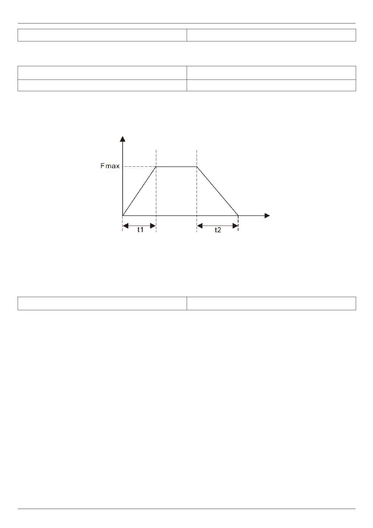
The acceleration time refers to the time required for the frequency inverter to accelerate from zero frequency to
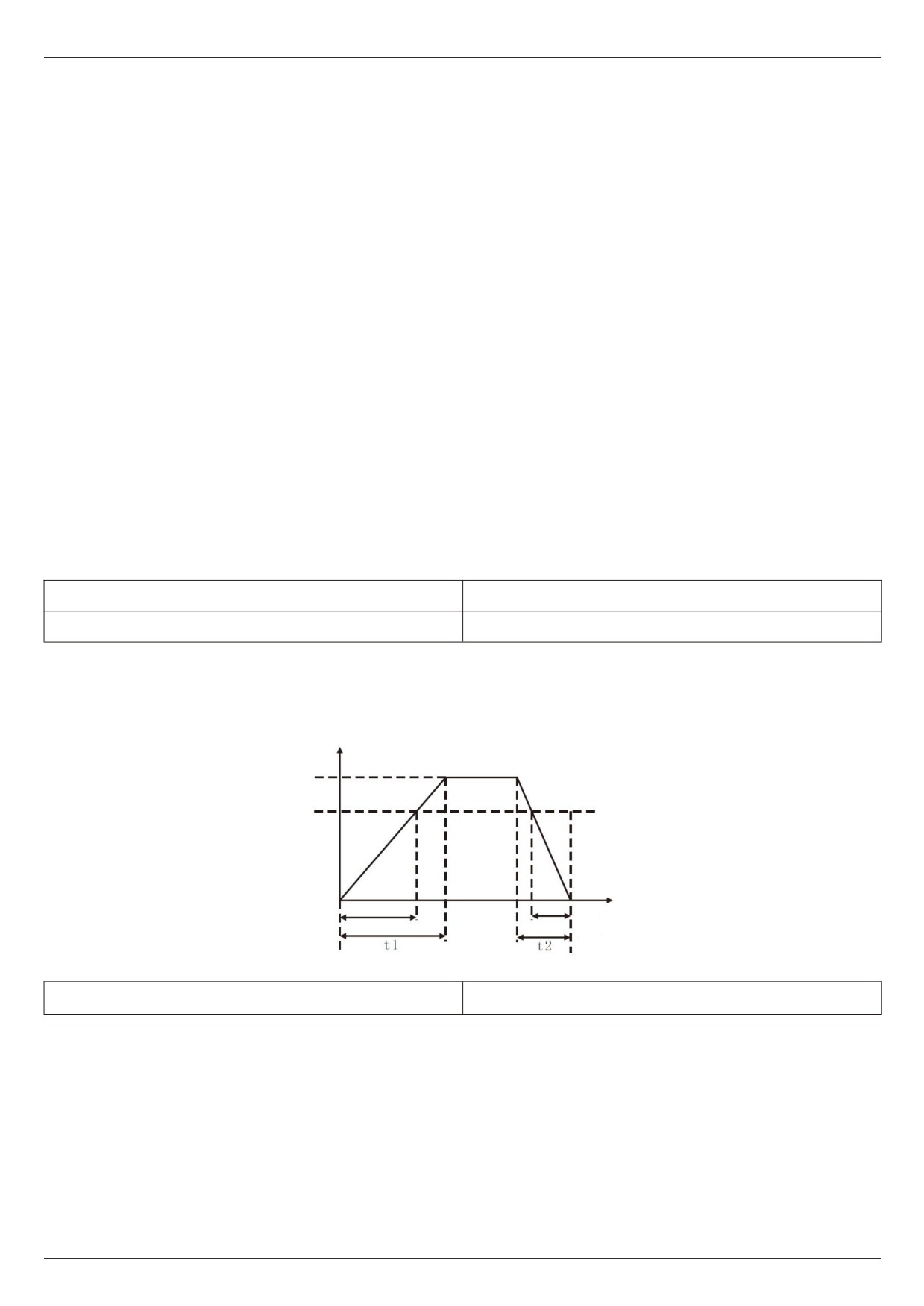
the acceleration and deceleration reference frequency (F0 - 13 is determined), as shown in figure 5 - 1, t1.
Deceleration time refers to the time required for the frequency inverter to decelerate to zero frequency from the
acceleration and deceleration reference frequency (F0 - 13), as shown in figure 5 - 1, t2.
Frequency
Time
Figure 5 - 1 schematic diagram of acceleration and deceleration time
HV480 defines a total of 4 groups of acceleration and deceleration times. The user can use the digital input
terminal X to switch between selections. The four groups of acceleration and deceleration times are set by the
following function codes:
Group 1: F0 - 10, F0 - 11; Group 2: F6 - 17, F6 - 18;
Group iii: F6 - 19, F6 - 20; Group 4: F6 - 21, F6 - 22.
F0 - 12 acceleration / deceleration time unit
0~2 [1]
0: the time unit is 1s.
1: the unit of time is 0.1 s.
2: the unit of time is 0.01 s.
Notes:
When modifying this function parameter, the number of decimal points displayed in the four groups of
acceleration and deceleration times will change, and the corresponding acceleration and deceleration times
will also change. Special attention should be paid to this during application.
- 60 -
Chapter V Description of parameters
F0 - 13 acceleration and deceleration time reference
0~2 [0]
frequency
0: the reference frequency is the maximum frequency (F0 - 16)
1: set the frequency at the reference frequency.
When F0 - 13 is selected as 1, the acceleration and deceleration time is related to the set frequency. If the set
frequency changes frequently, the acceleration of the motor will change. Attention should be paid when applying.
2: 100 Hz at reference frequency.
F0 - 14 shutdown mode
0~1 [0]
0: after the deceleration
Stop command is valid, the frequency inverter will reduce the output frequency according to the deceleration
time, and stop after the frequency is reduced to 0.
1: after the free
Stop command is valid, the frequency inverter will terminate the output immediately. At this time, the motor will
stop freely according to the mechanical inertia.
F0 - 15 droop control rate
0~10.00hz [0.00hz]
The droop rate allows for a slight speed difference between the master station and the slave station, thus
avoiding the rush between them. The default value for this parameter is 0.
Only when the main engine and the slave engine adopt the speed control mode will the droop rate need to be
adjusted. For each transmission process, the appropriate droop rate needs to be gradually found in practice. It is
recommended not to set F0 - 15 too large, otherwise the steady-state speed will drop significantly when the load is
large. Both the master and slave must set the droop rate.
Droop speed = synchronous frequency * output torque * (droop rate / 10)
For example: F0 - 15 = 1.00
50 Hz synchronous frequency rate, 50 % output torque, real frequency rate of frequency changer = 50 Hz - 50 *
(50 %)
(1.00/10) = 47.5hz
F0 - 16 maximum frequencies
50.00~500.00hz [50.00hz]
The analog input, pulse input (X5), multi-segment instruction, etc. are all 100.0 % of the respective calibration of
F0 - 16 when they are used as frequency sources.
F0 - 17 upper frequency sources
0~5 [0]
0: set by F0 - 18.
1: set by analog AI1.
2: set by analog AI2.
3: set by analog AI3.
4: set by digital pulse quantity X5.
5: through communication settings.
F0 - 18 upper limit frequency
Upper limit frequency ~ maximum frequency [ 50.00 Hz ]
F0 - 19 upper frequency offset
Upper limit frequency ~ maximum frequency [ 50.00 Hz ]
When the upper limit frequency source is set to analog quantity or pulse setting, F0 - 19 is used as the offset
amount of the set value, and the offset frequency is superposed with the upper limit frequency value set by F0 - 17 as
the set value of the final upper limit frequency.
- 61 -
Chapter V Description of parameters
F0 - 20 lower limit frequency
0.00 Hz ~ upper limit frequency [ 0.00 Hz ]
F0 - 21 operating formula for setting frequency lower 0~2 [0]
than lower limit frequency
When the frequency command is lower than the lower limit frequency set by F0 - 20, the frequency inverter can
be stopped, run at the lower limit frequency, or run at zero speed. Which operating mode can be set by F0 - 21
(operating mode with the set frequency lower than the lower limit frequency).
F0 - 22 carrier frequency
0.5 kHz ~ 16 kHz [model determination]
This function adjusts the carrier frequency of the frequency inverter. By adjusting the carrier frequency, the noise
of the motor can be reduced, the resonance point of the mechanical system can be avoided, the line current to the
floor drain can be reduced, and the interference generated by the frequency inverter can be reduced.
When the carrier frequency is low, the higher harmonic component of the output current increases and the motor
loss increases, and the temperature rise of the motor increases.
When the carrier frequency is high, the motor loss decreases and the temperature rise of the motor decreases,
but the frequency inverter loss increases and the frequency inverter temperature increases.
The rise increases and the interference increases. Adjusting the carrier frequency will affect the following
performance:
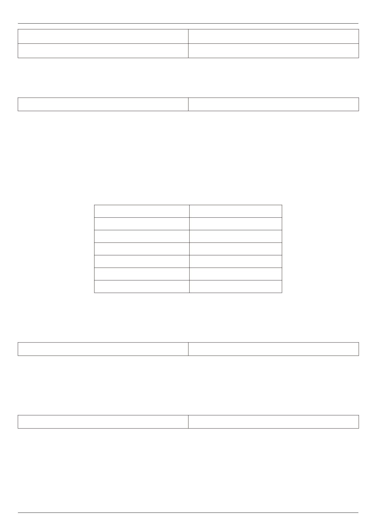
Carrier frequency
Low → high
Motor noise
Big → small
Output current waveform
Poor → good
Motor temperature rise
High → low
Temperature rise of frequency
Low → high
inverter
Leakage current
Small → big
External radiation interference
Small → big
The factory setting of carrier frequency is different for frequency inverters with different power. Although users
can modify it according to their needs, and they need to pay attention: if the carrier frequency setting is higher than
the factory value, and the temperature rise of the frequency inverter radiator will increase. At this time, users need to
use the frequency inverter by derating; otherwise the frequency inverter is in danger of overheating alarm.
F0 - 23 carrier frequencies adjusts with load size
0~1 [1]
The carrier frequency is adjusted with the load, which means that when the frequency inverter detects that the
load exceeds the rated level, and it will automatically reduce the carrier frequency so as to reduce the temperature
rise of the frequency inverter.
When the load decreases to a certain extent, the carrier frequency gradually returns to the set value. This
function can reduce the chance of over-heating alarm of frequency inverter.
F0 - 24 LED shutdown operation display selection
0~1 [0]
0: shutdown operation display is separated.
During operation, the LED display content is set by F0 - 37 / F0 - 38.
When shutting down, the LED display content is set by F0 - 39.
1: stop operation display does not separate
- 62 -
Chapter V Description of parameters
During operation, the LED display content is set by F0 - 37 / F0 - 38.
When shutting down, the LED display content is set by F0 - 37 / F0 - 38.
F0 - 26 digital setting frequency shutdown memory
0~1 [1]
selections
This function is only valid when the frequency source is set digitally.
0: “no memory" means that after the frequency inverter is shut down, the digital set frequency value is restored
to F0 - 09 (preset frequency) values, keyboard ▲ and ▼ keys or frequency correction by terminals up and down are
cleared.
1: “memory" means that after the frequency inverter is shut down, the digital set frequency will remain the set
frequency at the time of the last shutdown. Frequency correction by keys ▲, ▼ or terminals up and down remains
valid.
F0 - 27 runtime frequency command up / down reference
0~1 [1]
This parameter is valid only if the frequency source is set digitally.
0: the operating frequency is the benchmark.
When the ▲, ▼ keys or terminals up / down of the keyboard are operated, what method is used to correct the
set frequency, that is, the target frequency rate is increased or decreased based on the operating frequency.
1: set frequency as reference.
When the ▲, ▼ keys or terminals up / down of the keyboard are operated, what method is used to correct the
set frequency, that is, the target frequency the rate is increased or decreased based on the set frequency.
The difference between the two settings is obvious when the frequency inverter is in the process of acceleration
and deceleration, that is, if the frequency of operation of the frequency inverter, When the rate is different from the set
frequency, the different choices of this parameter are very different.
F0 - 28 motor selection
0~1 [0]
HV480 supports the application of time-sharing drive of two motors by frequency inverters. The two motors can
respectively set motor nameplate parameters, independent parameter tuning, select different control modes, and
independently set parameters related to operation performance, etc. The user selects the current motor parameter
group through the F0 - 28 function code, and who can also switch the motor parameters through the digital quantity
input terminal X. When the function code selection conflicts with the terminal selection, the terminal selection shall
prevail
0: motor 1.
The corresponding functional parameter groups of motor parameter group 1 are f1 group and F2 group.
1: motor 2
Motor parameter group 2 corresponds to functional parameter group FB.
F0 - 29 auxiliary frequency source y
0~9 [0]
When the auxiliary frequency source is given a channel as an independent frequency (i.e. the frequency source
is selected as X to Y switch), its usage is the same as that of the main frequency source X. the usage method can
refer to the relevant description of F0 - 03.
When the auxiliary frequency source is used for superposition and given (i.e. the composite implementation
frequency of the main frequency source X and the auxiliary frequency source Y is given), attention should be paid to:
1. When the auxiliary frequency source is given by numbers, the preset frequency (F0 - 09) does not work, and
the user can select the preset frequency (F0 - 09) through the keyboard ▲, ▼ key (or up and down of multi-function
input terminal) adjusts the frequency directly on the basis of the main given frequency.
2. When the auxiliary frequency source is given by analog input (AI1, AI2, and AI3) or pulse input, the input
setting of 100 % corresponds to the auxiliary frequency source range, which can be set through F0 - 30 and F0 - 31.
3. Frequency source for pulse input timing, similar to analog given. Tips: the selection of the auxiliary frequency
source Y and the selection of the main frequency source X cannot be set to the same channel, i.e. F0 - 03 and F0 -
29 should not be set to the same value, otherwise it will easily cause confusion.
- 63 -
Chapter V Description of parameters
F0 - 30 Selection of Y range of auxiliary frequency
0~1 [0]
source during superposition
F0 - 31 Auxiliary frequency source Y range when is
0~150% [0%]
superimposed
These two parameters are used to determine the adjustment range of the auxiliary frequency source when the
frequency source is selected as “frequency superposition".
F0 - 30 is used to determine the object corresponding to the auxiliary frequency source range. It can be selected
to be relative to the maximum frequency, or it can be with respect to the main frequency source x, if selected with
respect to the main frequency source, the range of the auxiliary frequency source will vary with the change of the
main frequency X.
F0 - 32 frequency source superposition selection
0~34 [0]
The given channel of frequency is selected through this parameter. The frequency is given by the combination of
the main frequency source X and the auxiliary frequency source Y.
Bit: frequency selection. Select the mode of frequency superposition or switching.
0: only the primary frequency X and the secondary frequency Y do not overlap. F=X。
1: the superposition mode of frequency is determined by 10 bits.
2: the main frequency X and the auxiliary frequency Y are switched through the No. 18 function of the X terminal.
Function terminal No. 18 is closed for auxiliary y, and the terminal is broken on for the main frequency Y
3: main frequency X and main and auxiliary operation results switch. Terminal switching function is No. 18.
4: secondary frequency Y and primary and secondary operation results switch. Terminal switching function code
No. 18.
10 bits: frequency primary and secondary operation relation
0: X+Y
1: X-Y
2: min (X, Y), whichever is the maximum in the primary and secondary
3: max (X, Y), minimum value in main and auxiliary
F0 - 33 Offset frequency of auxiliary frequency source
0 ~ maximum frequencies [0.00 Hz]
when is superimposed
When the frequency source is selected as the main and auxiliary operation, the offset frequency can be set
through F0 - 33, and the offset frequency can be superimposed on the main and auxiliary operation results to flexibly
cope with various requirements.
F0 - 34 command source bundling frequency source
0~999 [000]
Bit: panel command binding frequency source selection
0: no binding
1: digital setting frequency source.
2: AI1
3: AI2
4: AI3
5: pulse quantity X5
6: multi-segment speed
7: simple PLC
8: PID
9: communication given
10 bits: terminal command binding frequency source selection (0 ~ 9, same bit)
100 bits: communication command binding frequency source selection (0 ~ 9, same bit)
- 64 -
Chapter V Description of parameters
Defines the binding combination between three kinds of operation command channels and nine kinds of
frequency given channels to facilitate synchronous switching change.
The meaning of the given channel of the above frequency is the same as that of F0 - 03 selected by the main
frequency source X. please refers to F0 - 03 function code descriptions. Different run command channels can bind a
given channel with the same frequency.
When the command source has a bundled frequency source, other set frequency sources will no longer function
during the period when the command source is active.
F0 - 35 cooling fan control
0~1 [0]
0: fan running when running;
The frequency inverter operates the fan in the running state, the fan rotates when the radiator temperature is
higher than 40 degrees in the shutdown state, and the fan does not operate when the radiator temperature is lower
than 40 degrees in the shutdown state.
1: the fan has been running all the time;
The fan has been running since it was powered on.
F0 - 36 forward and reverse dead time
0.0s~3000.0s [0.0s]
Set the transition time at the output of 0 Hz during the forward and reverse transition of the frequency inverter, as
shown in figure 5 - 02:
Output frequency
Forward
Dead time
Reversal
Figure 5 - 02 schematic diagram of dead time for forward and reverse rotation
F0 - 37 operating parameter 1
0000~FFFF [H401F]
F0 - 38 operating parameter 2
0000~FFFF [H401F]
F0 - 39 shutdown parameters
0000~FFFF [H401F]
Please refer to the instructions in appendix 2.
- 65 -
Chapter V Description of parameters
F0 - 40 load speed display factor
0.0001~6.5000 [3.0000]
When it is necessary to display the load speed, the corresponding relation between the output frequency of the
frequency inverter and the load speed is adjusted through this parameter. Please refer to F0 - 41 for specific
correspondence.
F0 - 41 load speeds displays decimal places
0~32 [21]
Bit:
Used to set the number of decimal places for load speed display. The following example illustrates how to
calculate the load speed:
If the load speed ( u0 - 14 ) shows a coefficient F0 - 40 of 2.000 and the number of decimal places F0 - 40 of the load
speed is 2 ( 2 decimal places ), when the frequency inverter is running at 40.00 Hz, the load speed is 40.00 * 2.000 =
80.00
(2 decimal point display)
If the frequency inverter is stopped, the load speed is displayed as the speed corresponding to the set frequency,
i.e. “set load speed ". Taking the set frequency of 50.00 Hz as an example, the load speed in shutdown state is 50.00
* 2.000 = 100.00 (2 decimal point display)
10 bits:
1: U0 - 19 / U0 - 29 are displayed with 1 decimal point respectively.
2: U0 - 19 / U0 - 29 are displayed with 2 decimal point respectively.
F0 - 43 personality parameter mode display selection
0~11 [00]
Bit: user specified parameter display selection
0: not displayed
1: display
10 bits: user changes parameter display selection
0: not displayed
1: Display
The setting up of the parameter display mode is mainly to facilitate users to view the functional parameters of
different arrangement modes according to actual needs, and to provide three parameter display modes.
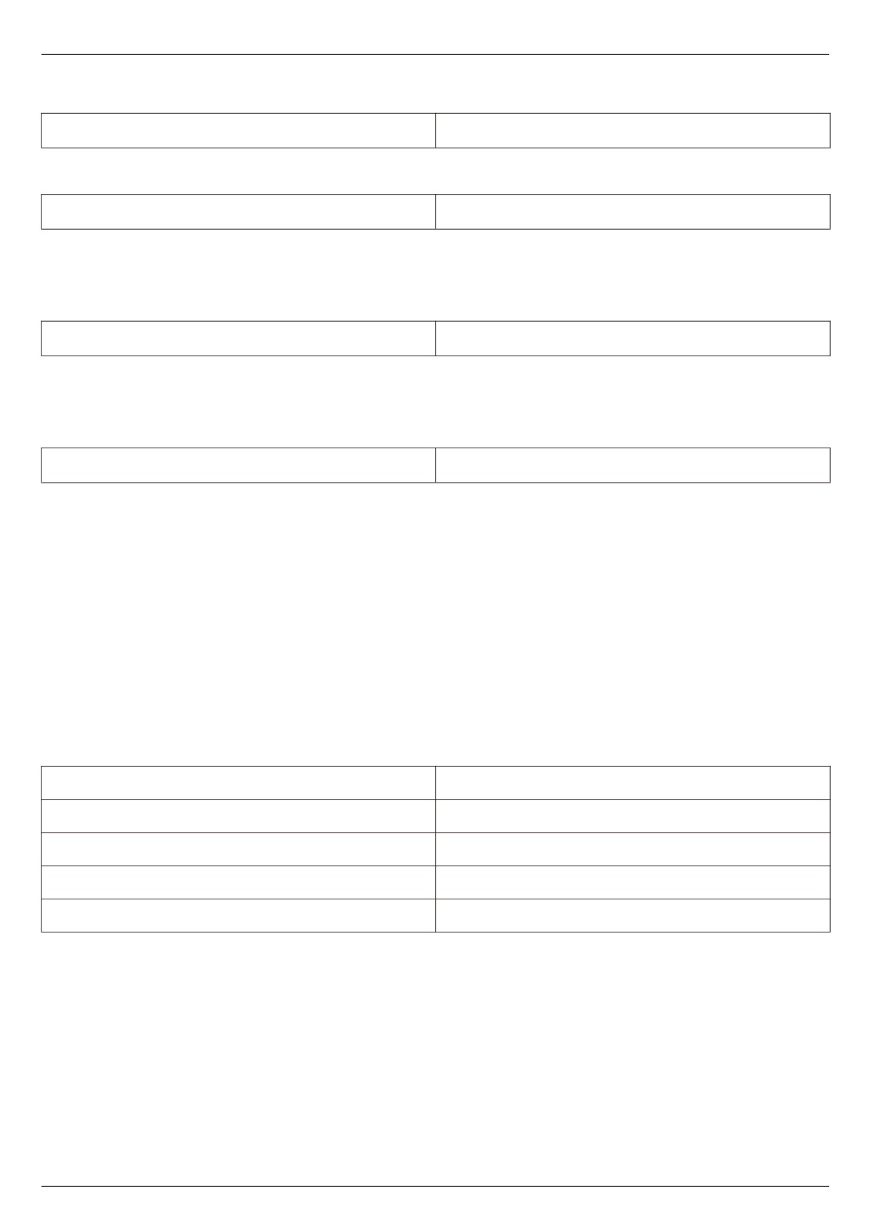
Name
Description
The functional parameters of the frequency inverter are
Function parameter mode
displayed in sequence, including F0 ~ FP, P0 ~ P3, U0~
UF functional parameter groups
The user customizes the individual function parameters
User - customized parameter method
displayed (up to 32). The user determines the function
parameters to be displayed through the Fe group.
Functional parameters inconsistent with factory
Method for user to change parameters
parameters
- 66 -
Chapter V Description of parameters
When there is a display for personality parameter mode display selection (F0 - 43), you can switch to different
parameter display modes through quick key at this time. The default value is only function parameter mode display.
F0 - 44 function code modification attribute
0~1 [0]
0: modifiable, user can modify function code through panel keyboard or communication.
1: cannot be modified. All function codes can only be viewed and cannot be modified.
F0 - 45 keyboard knob sensitivity
0~3 [2]
The greater the F0 - 45 setting, the more sensitive the keyboard shuttle (or up down operation) is, the smaller
the setting, and the less sensitive it is.
Note: this function is only valid for up and down addition and subtraction of level 0 menus, and other functions
are invalid.
F0 - 46 user password
0~65535 [0]
F0 - 46 sets any non-zero number, the password protection function takes effect. The next time you enter the
menu, you must enter the password correctly, and otherwise you cannot view and modify the function parameters.
Please keep in mind the user password you have set. If F0 - 46 is set to 00000, then the set user password will be
cleared and the password protection function will be invalid.
F0 - 47 initialization
0~65535 [0]
0: no operation.
1001: restore factory settings, excluding motor parameters
After setting F0 - 47 as 1001, most of the frequency inverter function parameters are restored to factory
parameters, but motor parameters, frequency command decimal point, fault record information, accumulated running
time, accumulated power-on time, and accumulated power consumption are not restored.
1002: clear record information
Clear frequency inverter fault record information, accumulated running time, accumulated power-on time, and
accumulated power consumption.
F1 Group first motor parameters
F1 - 01 rated power
0.1 kW ~ 1000.0 kW [ model determination ]
F1- 02 rated voltage
1V ~ 2000 V [ model determination ]
F1- 03 rated current
0.01A~655.35A ( frequency inverter power < = 55Kw )
F1 - 04 rated frequency
0.01 Hz ~ maximum frequency [ model determination ]
F1 - 05 rated rotational speed
1 rpm ~ 65535 rpm [ model determination ]
Set the parameters of the controlled motor
In order to ensure the control function, be sure to set F1-01~F1-05 correctly according to the nameplate parameters
of the motor.
In order to obtain better VF or vector control performance, motor parameters need to be tuned, and the accuracy of
the adjustment results is closely related to the correct setting of motor nameplate parameters.
- 67 -
Chapter V Description of parameters
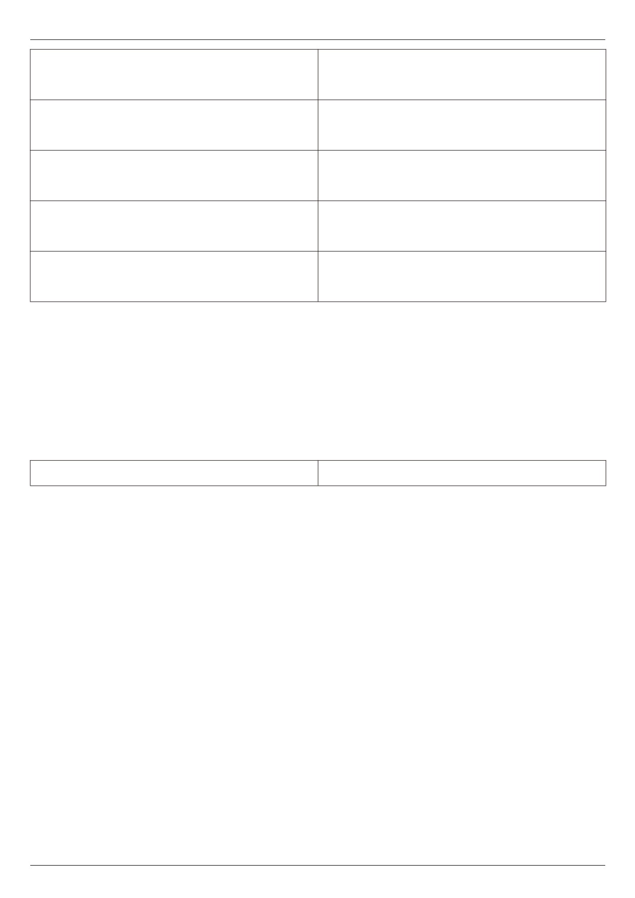
0.001Ω~65.535Ω( frequency inverter power ≤55kW )
F1-06 stator resistance of asynchronous motor
0.0001 ~ 6.5535 ( frequency inverter power > 55kW )
[ model determination ]
0.001Ω~65.535Ω( frequency inverter power ≤55kW )
F1-07 rotor resistance of asynchronous motor
0.0001 ~ 6.5535 ( frequency inverter power > 55kW )
[ model determination ]
0.01 ~ 655.35 mH ( frequency inverter power ≤ 55 kW )
F1-08 induction motor leakage reactance
0.001 ~ 65.535 mH ( frequency inverter power > 55 kW )
[ model determination ]
0.1 ~ 6553.5 mH ( frequency inverter power ≤ 55 kW )
F1-09 mutual inductance reactance of asynchronous
0.01 ~ 655.35 mH ( frequency inverter power > 55 kW )
motor
[ model determination ]
0.01A ~ F1 - 03 ( frequency inverter power ≤ 55kW )
F1-10 asynchronous motor no-load current
0.1A ~ F1 - 03 ( frequency inverter power > 55kW )
[ model determination ]
F1-06~F1-10 is parameters of asynchronous motors. These parameters are generally not found on the motor
nameplate and need to be automatically tuned by the frequency inverter. Among them, “asynchronous motor static
tuning" can only obtain F1-06~F1-08 three parameters, while " asynchronous motor complete tuning" can obtain not
only all five parameters here, but also encoder phase sequence, current loop PI parameters, etc.
When changing the rated power of the motor (F1 - 01) or the rated voltage of the motor (F1 - 02), the frequency
inverter will automatically modify the F1 - 06 ~ F1 - 10 parameter values to restore these 5 parameters to the
common standard Y series motor parameters. If it is impossible to tune the asynchronous motor on site, you can
enter the above-mentioned corresponding function code according to the parameters provided by the motor
manufacturer.
F0 - 29 motor parameters self - tuning
0~3 [0]
0: no operation.
1: simple static self - tuning.
It is suitable for asynchronous motors where large inertia loads are not easy to disengage and cannot be
rotated.
2: rotational self - tuning
During the complete setting process, the frequency inverter will first perform static setting, and then accelerate
to 80 % of the rated frequency of the motor according to the acceleration time F0 - 10. After maintaining for a period
of time, the frequency inverter will slow down and shut down according to the deceleration time F0 - 11 and end the
setting.
3. Advanced static self-tuning
Is applicable to the case where there is no encoder, and the motor parameters are self-learned when the motor
is at rest (at this time, the motor may still have slight shaking)
Description:
1. Tuning supports motor tuning in keyboard operation mode, terminal mode and communication mode.
2. In order to ensure the optimal control performance of the frequency inverter during vector control, please
disconnect the load from the motor and use rotational tuning to self-learn the motor parameters; otherwise it will
affect the vector control effect. Please use static tuning 2 when the motor has a large inertia load which is not easy to
disengage and vector control is required.
3. Steps
3.1 Motor type and nameplate parameters F1-00~F1-05 must be set correctly.
3.2 F1 - 29 = 1 or 2 or 3. The panel displays the word STUDY at this time.
- 68 -
Chapter V Description of parameters
3.3 Then press the run key, and the frequency inverter will be set.
3.4 When the operation light on the panel goes out, it indicates that the setting is done.
F2 Group motor vector control parameters
F2 group function codes are only valid for vector control and invalid for VF control.
F2 - 00 speed loop proportional gain kp1
1~100 [30]
F2 - 01 speed loop proportional gain Ti1
0.01~10.00 [0.50s]
F2 - 02 switching frequency f1
0.00~F2-05 [5.00hz]
F2 - 03 speed loop proportional gain kp2
1~100 [20]
F2 - 04 speed loop proportional gain Ti2
0.01~10.00 [1.00s]
F2 - 05 switching frequency F2
F2 - 05 ~ maximum frequency [10.00 Hz]
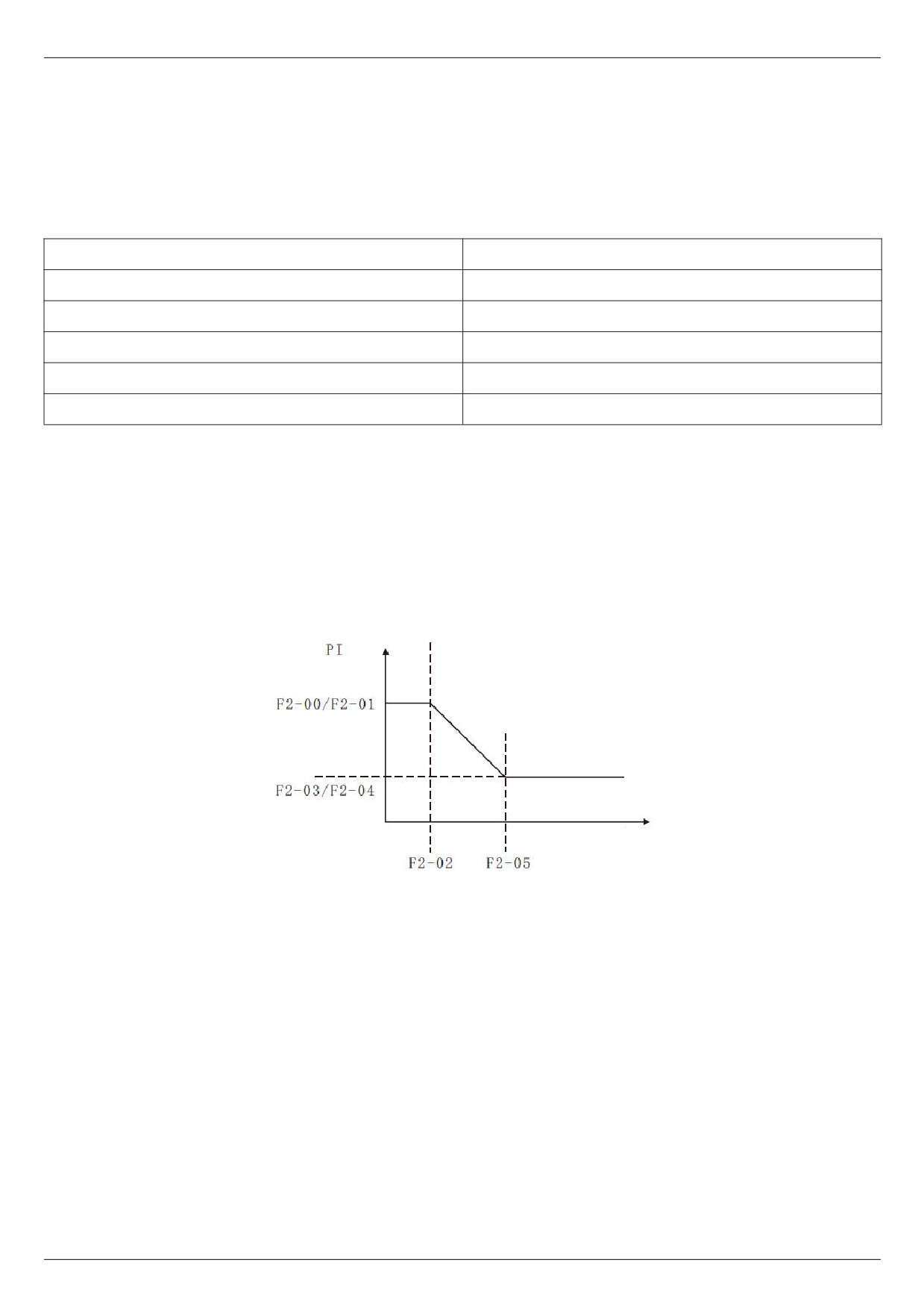
The frequency inverter operates at different frequencies, and different PI parameters of the speed loop can be
selected.
When the operating frequency is less than the switching frequency 1 (F2 - 02), the speed loop pi adjustment
parameters are F2 - 00 and F2 - 01.
When the operating frequency is greater than the switching frequency 2, the speed loop pi adjustment parameters
are F2 - 03 and F2 - 04.
The speed loop pi parameters between switching frequency 1 and switching frequency 2 are linearly switched by two
sets of pi parameters, as shown in figure 5 - 03:
Parameter
Frequency
Figure 5 - 03 pi parameter diagram
By setting the proportional coefficient and the integration time of the speed regulator, the speed dynamic
response characteristics of the vector control can be adjusted.
Increasing the proportional gain and decreasing the integration time can accelerate the dynamic response of the
speed loop. However, too much proportional gain or too little integration time may cause the system to oscillate.
The suggested adjustment method is:
If the factory parameters cannot meet the requirements, fine-tune them based on the factory value parameters
to increase the proportion and benefit first, so as to ensure that the system does not oscillate. Then reduce the
integration time so that the system has faster response characteristics and less overshoot.
For vector control without speed sensor, this parameter is used to adjust the speed stability accuracy of the
motor: when the motor is loaded with low speed, this parameter is increased, and vice versa.
Note: improper setting of pi parameters may lead to excessive speed overshoot. Even when overshoot falls
back, over-voltage faults occur.
- 69 -

Chapter V Description of parameters
F2-06 vector controlled slip gain
50%~200% [100%]
F2-07 SVC torque filter time constant
0.000s~0.100s [0.000s]
F2-09 torque upper limit source under speed control
0~5 [0]
mode
F2-10 torque upper limit digital setting under speed
0.0%~200.0% [150.0%]
control mode
In the speed control mode, the maximum output torque of the frequency inverter is controlled by the torque
upper limit source. 0: set by F2 - 10 digits.
1: AI1 analog setting.
2: AI2 analog setting.
3: AI3 analog setting.
4: XI pulse setting.
5: Communication settings.
Description:
F2 - 09 is used to select the setting source of the upper torque limit. When setting through analog quantity,
PULSE pulse and communication, 100 % of the corresponding setting corresponds to F2 - 10, while 100 % of F2 - 10
is the rated torque of the frequency inverter. For AI1, AI2, AI3, X5 settings, please refer to the introduction of F4 AI
curve.
When the selection is communication setting
The host computer writes -100.00% ~ 100.00% of the data through the communication address 0×1000, of
which 100.00 % corresponds to F2 - 10.
F3 Group V/F control parameters
This group of function codes is only valid for V/F control and invalid for vector control.
F3 - 00 V/F curve setting
0~11 [0]
0: straight line V/F.
Suitable for common constant torque load.
1: multipoint V/F.
Suitable for special loads such as dehydrators and centrifuges at this time, by setting F3 - 03 to F3 - 08
parameters, any desired VF relation curve can be obtained.
2: square V/F. Suitable for centrifugal loads such as fans and water pumps.
3 ~ 8: VF relation curve between straight line VF and square VF.
10: VF complete separation mode.
At this time, the output frequency of the frequency inverter and the output voltage are independent of each other.
The output frequency is determined by the frequency source, while the output voltage is determined by F3 - 13 (VF
separated voltage source).
VF complete separation mode is generally used in induction heating, frequency inverter power supply, torque
motor control and other occasions.
11: VF semi-detached mode.
V and F are proportional in this case, but the proportional relationship can be set by the voltage source F3 - 13,
and V and F are the relationship is also related to the rated voltage and frequency of F1 group motors.
Assuming that the voltage source input is X (X is a value of 0 - 100 %), the relationship between the frequency
inverter output voltage v and frequency f is: V/F = 2 * X * (rated voltage of motor) / (rated frequency of motor)
- 70 -
Chapter V Description of parameters
F3 - 01 torque boost
0.0 % ~ 30 % [ model determination ]
F3 - 02 torque boost cutoff frequency
0.00 Hz ~ maximum output frequency [ 50.00 Hz ]
In order to compensate for the V/F control low frequency torque characteristics, the frequency inverter output
voltage is compensated for some lift at low frequency. However, the setting of torque increase is too large, the motor
is easy to overheat, and the frequency inverter is easy to over current.
This parameter is recommended to be increased when the load is heavy and the starting torque of the motor is
insufficient. The torque lift can be reduced when the load is light.
When the torque increase is set to 0.0, the frequency inverter will automatically increase the torque. At this time,
the frequency inverter will automatically calculate the required torque increase value based on the motor stator
electrical resistance and other parameters.
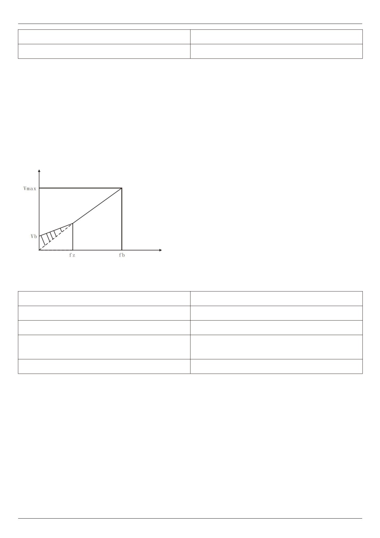
Torque boost torque cutoff frequency: under this frequency, the torque boost torque is valid. If it exceeds this set
frequency, the torque boost will fail. See figure 5 - 04 for details.
Output voltage
Vb: manual torque lifting diagram (lifting amount is shaded part)
fz: cut-off frequency of torque lifting
Vmax: maximum output voltage
FB: basic operating frequency
Output frequency
Figure 5 - 04 schematic diagram of manual torque boost
(The lifting amount is the shaded part)
F3 - 03 V/F frequency value f1
0.00Hz~F3-05 [0.00Hz]
F3 - 04 V/F voltage v1
0.0%~100.0% [0.0]
F3 - 05 V/F frequency value F2
F3-03~F3-07 [0.00Hz]
F3 - 05 ~ rated frequency of motor ( f1 - 04 )
F3 - 07 V/F frequency value F3
[0.00Hz]
F3 - 08 V/F voltage v3
0.0%~100.0% [0.0]
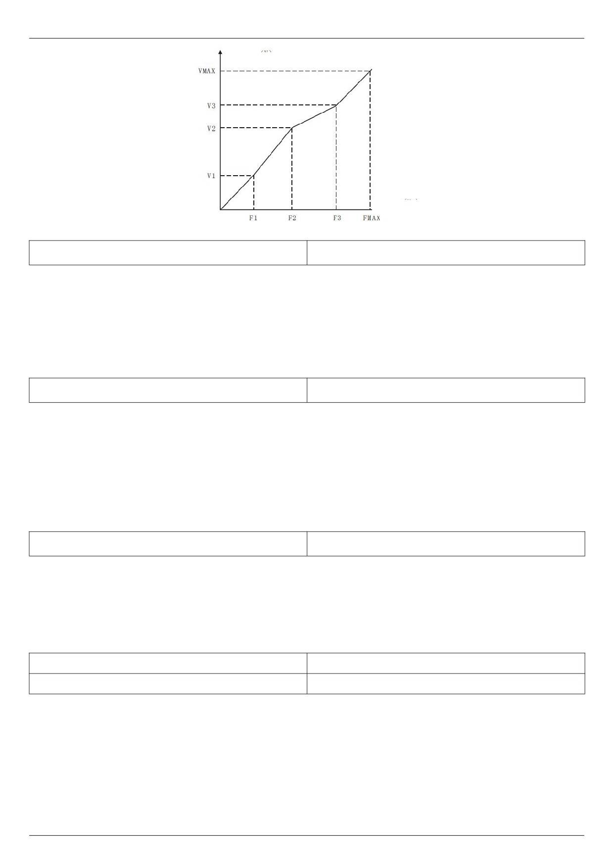
1. The curve of multi-point V/F shall be set according to the load characteristics of the motor. When setting, it is
necessary to confirm that the following conditions are established: v1 < v2 < v3, f1 < F2 < F3.
2. Figure 5 - 05 is a schematic diagram of setting multi-point VF curve.
Too high voltage setting at low frequencies may cause the motor to overheat or even burn down, and the
frequency inverter may be over-run or over-current protected.
- 71 -
Chapter V Description of parameters
Output voltage (V)
Frequency (Hz)
Figure 5 - 05 multi-point V/F curve setting diagram
F3 - 09 VF slip compensation gain
0%~200.0% [0.0%]
VF slip compensation can compensate the motor speed deviation of asynchronous motor when the load
increases, so that the motor speed can basically remain stable when the load changes.
VF slip compensation gain is set to 100.0 %, which indicates that the compensated slip is the rated slip of the motor
when the motor is under rated load.
When adjusting VF slip compensation gain, it is generally based on the principle that the motor speed is
basically the same as the target speed under the rated load. When the motor speed is different from the target value,
it is necessary to adjust the gain appropriately.
F3 - 10 VF over-excitation gain
0~200 [64]
In the process of frequency inverter deceleration, over-excitation control can suppress the rise of bus voltage
and avoid over-voltage fault. The greater the over-excitation gain, the stronger the suppression effect.
When the frequency inverter is prone to over-voltage alarm during deceleration, it is necessary to increase the
over-excitation gain. However, the over-excitation gain is too large, which easily leads to an increase in the output
current and needs to be weighed in the application.
When the inertia is very small, no voltage rise will occur during motor deceleration, it is recommended to set the
over-excitation gain to 0. It is also recommended to set the over-excitation gain to 0 when there is a braking
resistance.
F3 - 11 VF oscillation suppression gain
0 ~ 100 [model determination]
The gain is chosen to be as small as possible on the premise of validly suppressing oscillation so as not to
adversely affect VF operation. Please select the gain of 0 when the motor does not oscillate. Only when the motor is
obviously oscillating can the gain be appropriately increased. The greater the gain, the more obvious the suppression
of oscillation is.
When using the function of suppressing oscillation, it is required that the rated current and no-load current
parameters of the motor are accurate, otherwise VF oscillation suppression effect is not good.
F3 - 13 VF separated voltage source
0~8 [0]
F3 - 14 VF separated voltage digital setting
0~Rated voltage of motor [0]
VF separation is generally used in induction heating, frequency inverter power supply, torque motor control and
other occasions.
When VF separation control is selected, the output voltage can be set through function code F3 - 14, or it can
come from analog quantity, multi - Segments instruction, PLC, PID or communication given. When non-digital setting
is used, each set 100 % corresponds to the rated voltage of the motor, and when the percentage set by the analog
output is negative, the set absolute value is taken as the valid setting value.
- 72 -
Chapter V Description of parameters
0: the digital setting (F3 - 14) Voltage is set directly by F3 - 14.
1: AI1
2: AI2
3: AI3
The voltage is determined by the analog input terminal.
4. Pulse pulse setting (XI5)
Voltage is given by terminal pulse.
Pulse given signal specification: voltage range 9V~30V, frequency range 0kHz~100kHz.
5. Multiple instructions
When the voltage source is a multi-segment instruction, F5 group and FC group parameters should be set to
determine the correspondence between a given signal and a given voltage. The FC group parameter multi-segment
command gives 100.0 %, which is the percentage relative to the rated voltage of the motor.
6. When the simple PLC
Voltage source is a simple PLC, FC group parameters need to be set to determine the given output voltage.
7. PID
The output voltage is generated according to the PID closed loop. Please refer to FA group PID for details.
8. Communication given
The voltage is given by the upper computer through communication.
VF separation voltage source selection is similar to frequency source selection; see F0 - 03 main frequency
source selection introductions. Of which, 100.0 % of the corresponding setting for each type of selection refers to the
rated voltage of the motor (taking the absolute value of the corresponding setting value)
F3 - 15 VF separation voltage acceleration time
0.0S~1000.0S [0.0S]
F3 - 16 VF separation voltage deceleration time
0.0S~1000.0S [0.0S]
The voltage acceleration time for VF separation refers to the time required for the output voltage to accelerate
from 0 to the rated voltage of the motor, as shown in T1 in figure 5 - 06.
The voltage deceleration time for VF separation refers to the time required for the output voltage to decelerate
from the rated voltage of the motor to 0, as shown in figure 5 - 06.
Output voltage
Rated voltage of motor
Target voltage
Time
Actual acceleration time
Actual deceleration time
Sets the acceleration time
Sets the deceleration time
Figure 5 - 06 V/F separation diagram
F3 - 17 VF Shutdown mode for separations
0~1 [0]
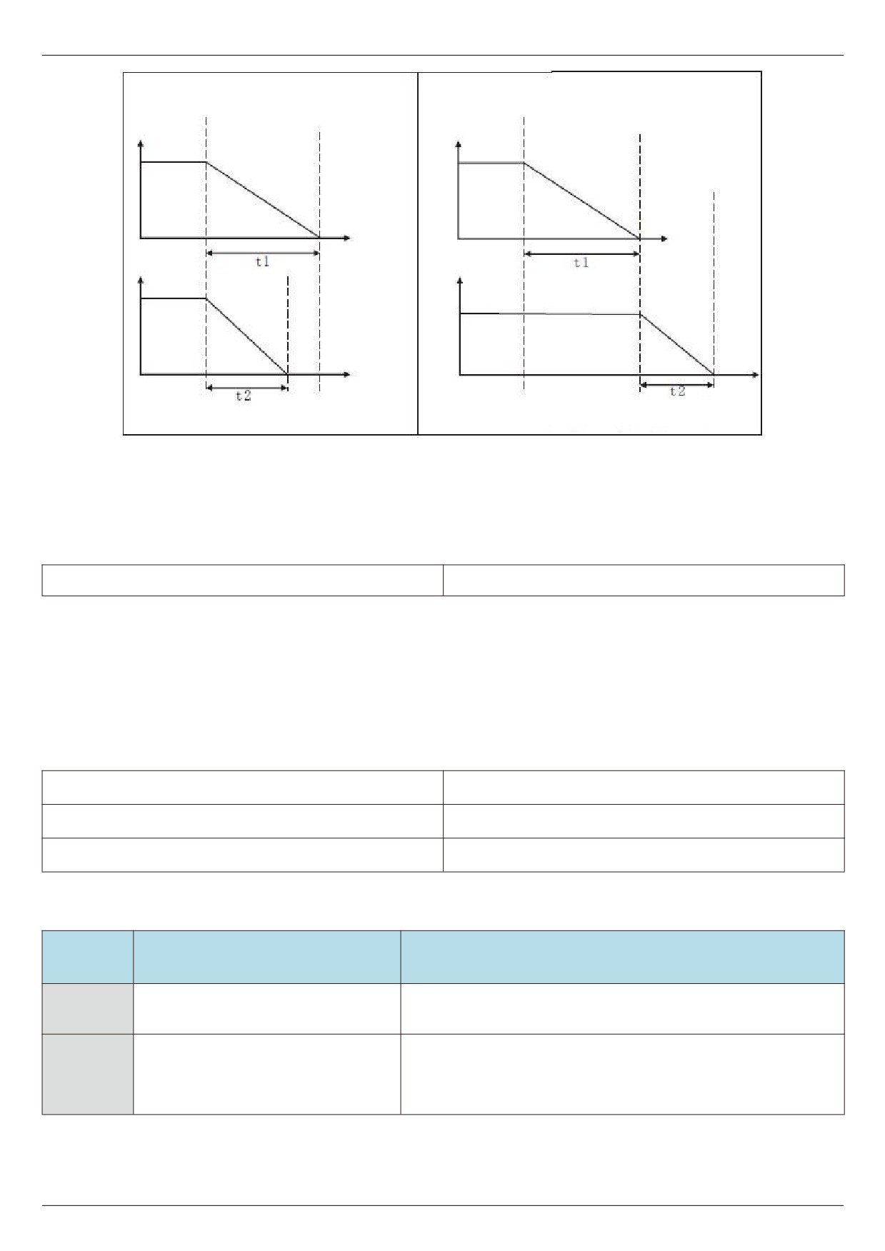
0: frequency and voltage independently reduced to 0.
1: the voltage is reduced to zero before the frequency is reduced.
- 73 -
Chapter V Description of parameters
F3 - 17 = 0 V/F independent deceleration mode
F3 - 17 = 1 first step-down and then step-down mode
Output voltage
Time
Output frequency
Time
T2 t1 is that actual time require to reduce the voltage to
T2 t1 is that actual time require to reduce the voltage to zero
zero
T2 is that actual time require to reduce the frequency to zero
T2 is that actual time require to reduce the frequency to
zero
Figure 5 - 07 V/F separation shutdown process diagram
F4 Group output terminals
F4 - 00 FM terminal output mode selection
0~1 [0]
The FM terminal is a programmable multiplex terminal, which can be used as a high-speed pulse output terminal
(FMP) or as a switch output terminal (FMR) with open collector.
0: high-speed pulse output terminal.
When outputting FMP as pulse, the highest frequency of the output pulse is 100 kHz. See F4 - 06 for FMP
related functions instruction.
1: Open collector output terminal.
When switching output is used, the output function is set by F4 - 01 function code.
F4-01 FM Open collector output terminal
0~42 [0]
F4-02 relay output function selection (T/A-T/B-T/C)
0~42 [2]
F4-04 DO1 open collector output terminal
0~42 [0]
The function of the multi-function output terminal is explained as follows:
Setting
Functionalities
Description
value
0
No output
The output terminal has no function
Indicates that the frequency inverter is running and has an
1
The frequency inverter is in operation
output frequency (which can be zero). At this time, the on signal
is output.
- 74 -
Chapter V Description of parameters
Setting
Functionalities
Description
value
When the frequency inverter fails and the fault stops, an on
2
Fault output ( fault shutdown )
signal is output.
Frequency level detection FDT1
Please refer to the descriptions of function codes F4 - 24 and
3
output
F4 - 25.
4
Frequency arrival
Please refer to the description of function code F4 - 28.
When the frequency inverter is running and the output
Zero speed operation ( no output
5
frequency is 0, the on signal is output. This signal is OFF when
during shutdown )
the frequency inverter is in shutdown state.
Before the motor overload protection action, judge according to
the threshold of overload pre - alarm, and output an on signal
6
Motor overload pre - alarm
after exceeding the pre-alarm threshold. Refer to function code
F9 - 00 ~ F9 - 02 for motor overload parameter setting.
frequency inverter overload pre -
Output on signal 10s before frequency inverter overload
7
alarm
protection occurs.
When the count value reaches the value set by F8 - 31, an on
8
Set the count value to reach
signal is output.
When the count value reaches the value set by F8 - 32, an on
9
Specified count value arrives
signal is output. Refer to FB group function description for
counting function
When the detected actual length exceeds the length set by F8 -
10
Length arrival
28, an on signal is output.
When the simple PLC runs through a cycle, a pulse signal with
11
PLC cycle completed
a width of 250ms is output.
When the accumulated running time of the frequency inverter
12
Accumulated operating time arrives
exceeds the time set by F8 - 01, an ON signal is output.
When the set frequency exceeds the upper limit frequency or
the lower limit frequency and the output frequency of the
13
Frequency limit
frequency changer also reaches the upper limit frequency or
the lower limit frequency, an ON signal is output.
In the speed control mode, when the output torque reaches the
14
Torque limitation
torque limit, the frequency inverter is in stall protection state
and outputs an ON signal at the same time.
When the power supply of the main circuit and the control
circuit of the frequency inverter has stabilized and the
15
Operational readiness
frequency inverter has not detected any fault information, and
the frequency inverter is in an operable state, an ON signal is
output.
When the value of analog input AI1 is greater than the input
16
AI1>AI2
value of AI2, an ON signal is input.
When the operating frequency reaches the upper limit
17
Upper frequency arrival
frequency, an ON signal is input.
When the operating frequency reaches the lower limit
Lower limit frequency reached ( not
18
frequency, an ON signal is input. This signal is OFF when the
input during shutdown )
machine is stopped.
When the frequency inverter is in the under voltage state, an
19
Under voltage state output
ON signal is input.
20
Communication settings
Please refer to the communication protocol.
- 75 -
Chapter V Description of parameters
Setting
Functionalities
Description
value
21
Reserve
Reserve
22
Reserve
Reserve
Zero speed operation in 2 ( also input
When the output frequency of the frequency inverter is 0, the
23
during shutdown)
on signal is output. This signal is also in shutdown state.
When the frequency inverter's accumulated power-on time (U0
24
Cumulative power-on time arrives
- 71) exceeds the time set by F8 - 00, the frequency inverter
outputs an on signal.
Frequency level detection FD T2
Please refer to the descriptions of function codes F4 - 26 and
25
output
F4 - 27.
Please refer to the descriptions of function codes F4 - 29 and
26
Frequency 1 reaches output
F4 - 30.
Please refer to the descriptions of function codes F4 - 31 and
27
Frequency 2 reaches output
F4 - 32.
Please refer to the descriptions of function codes F4 - 33 and
28
Current 1 reaches output
F4 - 34.
Please refer to the descriptions of function codes F4 - 35 and
29
Current 2 reaches output
F4 - 36.
When the timing function selection (F8 - 04) is valid, the on
30
Timed arrival output
signal will be output after the current running time of the
frequency inverter reaches the set timing time.
When the value of analog input AI1 is greater than F4 - 37 (AI1
31
Ai1 input overrun
input protection upper limit) or less than F4 - 38 (AI1 input
protection lower limit), the signal is input.
When the frequency inverter is in the off-load state, an ON
32
Off loading
signal is output.
When the frequency inverter is in reverse operation, an ON
33
In reverse operation
signal is output.
Please refer to the descriptions of function codes F4 - 33 and
34
Zero current state
F4 - 34
When the frequency inverter module radiator temperature ( U0
35
Module temperature reached
- 69 ) reaches the set module temperature reaching value ( F4 -
39 ), an ON signal is output
Please refer to the descriptions of function codes F4 - 42 and
36
Software current overrun
F4 - 43.
When the operating frequency reaches the lower limit
Lower limit frequency reached
37
frequency, an ON signal is output. This signal is also ON during
( shutdown also output )
shutdown.
When the frequency inverter fails and the processing mode of
38
Alarm output
the failure is continuous operation, the frequency inverter gives
an alarm output.
When the starting operation time of the frequency inverter
39
The running time has arrived
exceeds the time set by F8 - 07, the on signal is output.
40
Fault output
Under voltage does not output.
41
AI1 is lower than lower limit output
When the value of AI1 is lower than F4 - 37, output
42
AI1 above upper limit output
When AI1 value is higher than F4 - 38, output
43
AI2 output below lower limit
When AI2 value is lower than F4 - 37, output
44
AI2 above upper limit output
When AI2 value is higher than F4 - 38, output
F4-06 FM output function selection ( pulse output terminal )
0~16 [0]
F4-07 AO1 output function selection
0~16 [0]
F4-08 AO2 output function selection
0~16 [1]
- 76 -
Chapter V Description of parameters
The FMP terminal output pulse frequency ranges from 0.01 kHz to F4 - 09 (FMP output the maximum frequency),
and F4 - 09 can be set between 0.01 kHz and 100.00 kHz.
The analog outputs AO1 and AO2 range from 0V to 10V, or 0 mA to 20 mA.
The calibration relationship between the range of pulse output or analog output and corresponding functions is
shown in the following table:
Setting
Functionalities
Description
value
0
Running frequency
0 ~ maximum output frequency
1
Set frequency
0 ~ maximum output frequency
2
Output current
0 ~ 2 times rated current of motor
3
Output torque ( absolute value )
0 ~ 2 times rated torque of motor
4
Output power
0 ~ 2 times rated power
5
Output voltage
0 ~ 1.2 times rated voltage of frequency inverter
6
PULSE pulse input
0.01kHz~100.00kHz
7
AI1
0V~10V
8
AI2
0V~10V(or 0~20mA)
9
AI3
0V~10V
10
Length
0 ~ maximum set length
11
count value
0 ~ maximum count value
12
Communication settings
0.0%
- 100.0%
Rotational speed corresponding to 0 ~ maximum output
13
Motor rotational speed
frequency
14
Output current
0.0A~1000.0A
15
Output voltage
When 0.0v to 1000.0v
16
Output torque ( actual value )
- 2x motor rated torque ~ 2x motor rated torque
F4 - 09 FMP output maximum frequency
0.01kHz~100.00kHz [50.00Khz]
F4 - 10 A01 zero offset coefficient
-100.0%~+100.0% [0.0%]
F4 - 11 A01 gain
-10.00~+10.00 [1.00]
F4 - 12 A02 zero offset coefficient
-100.0%~+100.0% [0.0%]
F4 - 13 A02 gain
-10.00~+10.00 [1.00]
- 77 -
Chapter V Description of parameters
The above function codes are generally used to correct the zero offset of the analog output and the deviation of
the output amplitude. It can also be used to customize the required AO output curve.
If the zero offset is represented by “b", the gain is represented by k, the actual output is represented by y, and
the standard output is represented by x, the actual output is: Y = kX + b * 10V.
Among them, the zero offset coefficient of AO1 and AO2 is 100 % corresponding to 10v (or 20mA), and the
standard output refers to the output of 0V - 10V (or 0mA - 20mA) corresponding to the amount indicated by the
analog output without zero offset and gain correction.
For example, if the analog output content is operating frequency, it is expected to output 8v at frequency 0 and
3v at maximum frequency, then the gain should be set to " - 0.50" and the zero offset should be set to " 80 %".
F4-17 FMR output delay time
0.0s~3600.0s [0.0S]
F4-18 relay1 output delay time
0.0s~3600.0s [0.0S]
F4-20 D01 output delay time
0.0s~3600.0s [0.0S]
Set the output terminals FMR, relays 1, D01 to delay the change from the state to the actual output.
F4 - 22 selection of valid state of output terminal
00000~11111 [00000]
BIT0:FMR positive and negative logic
definition
BIT1: relay 1 positive and negative logic
definition
BIT3: D01 positive and negative logic
definition
Figure 5 - 08
Defines the output logic of the output terminals FMR, relay 1, D01. 0: positive logic, the digital quantity output
terminal and the corresponding common terminal are connected in a valid state and disconnected in an invalid state;
1: reverse logic, the connection between the digital quantity output terminal and the corresponding common
terminal is invalid, and the disconnection is valid.
F4-24 frequency detection value ( FD t1 )
0.00 Hz ~ maximum frequency [ 50.00 Hz ]
F4-25 frequency detection lag value ( FD t1 )
0.0 % ~ 100.0 % ( FD t1 level ) [ 5.0 % ]
F4-26 frequency detection value ( FD T2 )
0.00 Hz ~ maximum frequency [ 50.00 Hz ]
F4-27 frequency detection lag value ( FD T2 )
0.0 % ~ 100.0 % ( FDT2 level ) [ 5.0 % ]
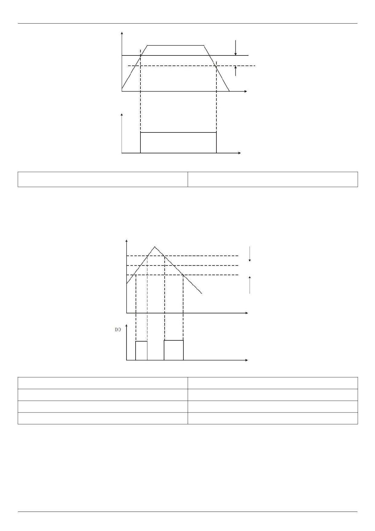
When the operating frequency is higher than the frequency detection value, the multi-function output ( No. 03
FDT1, No. 25 FDT2 ) D0 of the frequency inverter outputs on signal, while when the frequency is lower than the
detection value by a certain frequency value, the D0 output on signal is cancelled.
The above parameters are used to set the detection value of the output frequency and the hysteresis value of
the release of the output action. Wherein F4 - 25 / F4 - 27 is the percentage of lag frequency relative to the frequency
detection value F4 - 24 / F4 - 26. Figs. 5 - 09 show the intent of the FDT function.
- 78 -
Chapter V Description of parameters
Output voltage
FDT lag
Time
Detected
signal
Figure 5 - 09 FDT level diagram
F4 - 28 frequencies reaches detection width
0.00 ~ 100 % (maximum frequency) [0.0 %]
When the operating frequency of the frequency inverter is within a certain range of the target frequency, the
multi-function (04) D0 of the frequency inverter outputs an on signal.
This parameter is used to set the detection range of frequency arrival and this parameter is a percentage of the
maximum frequency. Figure 5 - 10 is a schematic diagram of frequency arrival.
Output voltage
Setup frequency
Detection width
Figure 5 - 10 schematic diagram of frequency arrival detection amplitude
F4-29 random arrival frequency detection value 1
0.00 Hz ~ maximum frequency [ 50.00 Hz ]
F4-30 random arrival frequency detection width 1
0.0%~100.0% [0.0%]
F4-31 random arrival frequency detection value 2
0.00 Hz ~ maximum frequency [ 50.00 Hz ]
F4-32 random arrival frequency detection width 2
0.0%~100.0% [0.0%]
When the output frequency of the frequency inverter is within the positive and negative detection range of any
frequency detection value, the multi-function DO (No. 26 and No. 27) outputs on signal
HV480 provides two groups of random arrival frequency detection parameters, setting frequency values and
frequency detection ranges respectively. Figure 5 - 11 is a schematic diagram of this function.
- 79 -
Chapter V Description of parameters
F4-33 arbitrarily reaching current 1
0.0 % ~ 300.0 % ( rated current of motor ) [ 100.0 % ]
F4-34 the width of current 1 is arbitrarily reach
0.0 % ~ 300.0 % ( rated current of motor ) [ 0.0% ]
F4-35 arbitrarily reaching current 2
0.0 % ~ 300.0 % ( rated current of motor ) [ 100.0% ]
F4-36 the width of current 2 is arbitrarily reach
0.0 % ~ 300.0 % ( rated current of motor ) [ 0.0% ]
When the output current of the frequency inverter is set within the positive and negative detection width of any
arriving current, the multi-function DO (No. 28 and No. 29) of the frequency inverter outputs on signal.
HV480 provides two groups of random arrival currents and detection width parameters. The detection principle
is similar to F4 - 29 ~ F4 - 32.
F4 - 37 AI1 input voltage protection value lower
0.00V~F4-38 [3.1V]
limi-
F4
38 upper limit of AI1 input voltage
F4-37~10.00V [6.8V]
protection value
When the analog input value of AI1 is greater than F4 - 38, or AI1 input value is less than F4 - 37, the
multi-function D0 (31) of the frequency changer outputs an “AI1 input overrun" ON signal to indicate whether the
input voltage of AI1 is within the set range.
F4 - 39 module temperatures reached
0 ~ 100 [75°C]
When the frequency inverter radiator temperature reaches the temperature, the multi-function DO of the
frequency inverter outputs the “module temperature reaches" ON message
F4 - 40 zero current detection level
0.0 % ~ 300.0 % ( rated current of motor ) [ 5.0% ]
F4 - 41 zero current detection delay time
0.00s~600.00s [0.10s]
When the output current of the frequency inverter is less than or equal to the zero current detection level and the
duration exceeds the zero current detection delay time, the frequency inverter multifunction ( No. 34 ) DO outputs ON
signal.
0.0 % ( no detection );
F4 - 42 output current overrun value
0.1% ~ 300.0 % ( rated current of motor ) [ 200.0% ]
F4 - 43 output current overrun detection delay
0.00s~600.00s [0.00s]
time
When the output current of the frequency inverter is greater than or exceeds the limit detection point and the
duration exceeds the software over current point detection delay, the frequency inverter multifunction (No.
36) DO
outputs on signal.
F5 Group input terminals
F5 - 00 X 1 terminal function selection
0~60 [1]
F5 - 01 X 2 terminal function selection
0~60 [2]
F5 - 02 X 3 terminal function selection
0~60 [9]
F5 - 03 X 4 terminal function selection
0~60 [12]
F5 - 04 X 5 terminal function selection
0~60 [13]
F5 - 05 X 6 terminal function selection
0~60 [14]
F5 - 06 X 7 terminals function selection
0 ~ 60 [8]
- 80 -
Chapter V Description of parameters
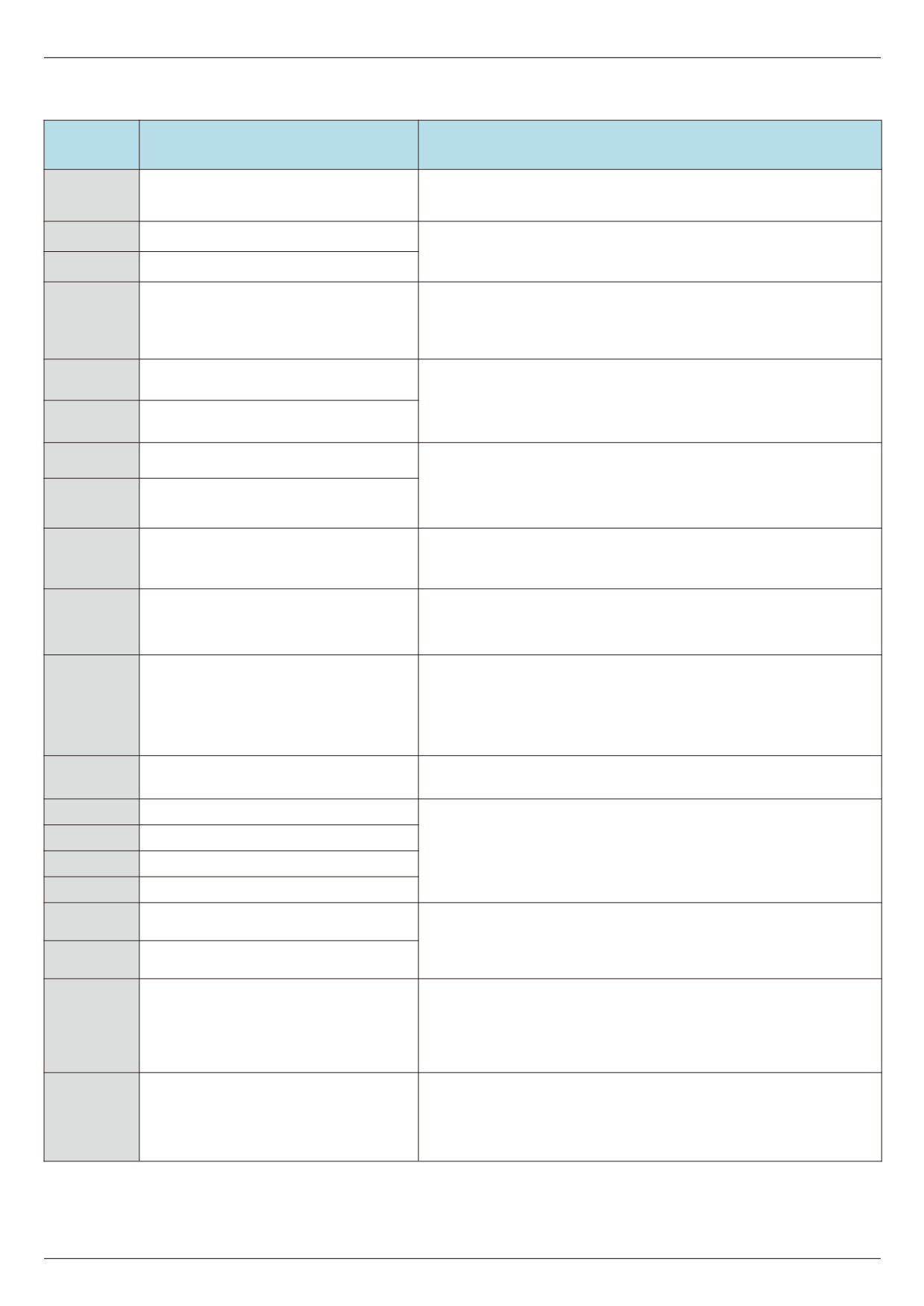
These parameters are used to set the functions of the digital multi-function input terminals and the functions that
can be selected are shown in the following table:
Setting
Functionalities
Description
value
The unused terminals can be set to “no function" to prevent
0
Nonfunctional
mis-operation.
1
Forward run ( FWD )
The forward rotation and reverse rotation of the frequency
inverter are controlled through external terminals.
2
Reverse run (REV)
Through this terminal, it is determined that the frequency
inverter operation mode is a three-wire control mode. Please
3
Three - wire operation control
refer to the description of function code F5 - 11 (“terminal
command method”) for details.
FJOG is JOG forward rotation, RJOG is JOG reverse rotation.
4
Forward JOG (FJOG)
Refer to the function code for JOG operation frequency and
JOG acceleration / deceleration time description of F6 - 13, F6
5
Reverse JOG (RJOG)
- 14, F6 - 15.
6
Terminal UP
The increment and decrement instructions of the frequency are
modified when the frequency is given by the external terminal.
When the frequency source is set to digital setting, the setting
7
Terminal DOWN
frequency of the section can be adjusted up and down.
The frequency inverter blocks the output. At this time, the stop
8
Free parking
process of the motor is not controlled by the frequency
changer.
The function of using terminals to reset faults. Same function
9
Fault reset(RESET)
as reset key on keyboard. This function can be used to reset
the remote fault barrier.
The frequency inverter decelerates and stops, but all operating
parameters are memorized. Such as PLC parameters, swing
10
Suspension of operation
frequency parameters and PID parameters. After this terminal
signal disappears, the frequency inverter returns to the
operating state before parking.
When the signal is sent to the frequency inverter, the frequency
11
External fault normally open input
inverter reports the failure ETF.
12
Multi-segment command terminal 1
13
Multi-segment command terminal 2
The speed of 16 segments can be realized through 16 States
of the four terminals. See attached table 1 for details.
14
Multi-segment command terminal 3
15
Multi-segment command terminal 4
Acceleration and deceleration time
16
Through the four States of the two terminals, the choice
selection terminal 1
between the four acceleration and deceleration times can be
Acceleration and deceleration time
17
realized, see table 2 for details.
selection terminal 2
Used to switch and select different frequency sources.
According to the setting of the frequency source selection
18
Frequency source switching
function code (F0 - 32); this terminal is used to switch between
two frequency sources when switching between two frequency
sources is set as the frequency source.
When the frequency is given as a digital frequency, this
UP/DOWN setting cleared ( terminal,
terminal can clear the frequency value changed by the terminal
19
keyboard )
UP/DOWN or the keyboard UP/DOWN to restore the given
frequency to the value set in F0 - 09.
- 81 -
Chapter V Description of parameters
Setting
Functionalities
Description
value
When the command source is set to terminal control (F0 - 02 =
1), this terminal can switch between terminal control and
Control command switching terminal
keyboard control.
20
1
When the command source is set to communication control (F0
- 02 = 2), this terminal can switch between communication
control and keyboard control.
Ensure that the frequency inverter is not affected by external
Acceleration and deceleration
21
signals (except shutdown command) and maintain the current
prohibition
output frequency.
The PID is temporarily disabled; the frequency inverter
22
PID pause
maintains the current output frequency and no longer performs
PID adjustment of the frequency source.
The PLC is suspended during the execution process. When the
23
PLC status reset
PLC runs again, the frequency inverter can be restored to the
initial state of the simple PLC through this terminal.
The frequency inverter outputs at the center frequency. The
24
The pendulum frequency suspended
frequency swing function is suspended.
25
Counter input
Input terminal of counting pulse.
26
Counter reset
The counter status is cleared.
27
Length count input
Input terminal for length count.
28
Length reset
Length zero clearing
It is forbidden for the frequency inverter to carry out torque
29
Torque control prohibited
control, and the frequency inverter enters the speed control
mode.
PULSE(Pulse) frequency input
30
X5 functions as a pulse input terminal.
( valid only for X5 )
31
Reserve
Reserve
When this terminal is active, the frequency inverter switches
32
Immediate DC braking
directly to the DC braking state
When the normally closed signal of an external fault is sent to
33
External fault normally closed input
the frequency inverter, the frequency inverter reports the fault
ETF and stops the operation.
If this function is set to active, when the frequency changes, the
34
Frequency modification prohibition
frequency inverter will not respond to the frequency change
until the terminal status is active.
The direction of PID action is
When this terminal is active, the direction of PID action is
35
reversed
opposite to the direction set by FA - 03
When the keyboard is controlled, this terminal can be used to
36
External parking terminal 1
stop the frequency inverter, which is equivalent to the function
of the STOP key on the keyboard.
Used for switching between terminal control and
Control command switching terminal
communication control. If the source is selected as terminal
37
2
control, the system will switch to communication control when
the terminal is active; on the contrary, it is also the opposite.
When this terminal is valid, the integral adjustment function of
38
PID integral suspended
the PID is suspended, but the proportional adjustment and
differential adjustment functions of the PID are still valid.
Frequency source X switches to
If the terminal is valid, the frequency source X is replaced by a
39
preset frequency
preset frequency ( F0 - 09 )
Frequency source Y switches to
This terminal is valid, then the frequency source Y is replaced
40
preset frequency
by a preset frequency ( F0 - 09 )
- 82 -
Chapter V Description of parameters
Setting
Functionalities
Description
value
2 sets of motor parameters can be switched through the 2
41
Motor selection terminal 1
states of terminals, see table 3 for details.
42
Reserve
Reserve
When the PID parameter switching condition is X terminal (FA -
18 = 1), when the terminal is invalid, the PID parameters are FA
43
PID parameter switching
- 05 ~ FA - 07; When the terminal is valid, FA - 15 ~ FA - 17 will
be used.
44
User - defined fault 1
When user-defined faults 1 and 2 are valid, the frequency
inverter alarms UEF1 and UEF2 respectively.
45
User - defined fault 2
Before the motor overload protection action, judge according to
the threshold of overload pre - alarm, and output an on signal
46
Motor overload pre - alarm
after exceeding the pre-alarm threshold. Refer to function code
F9 - 00 ~ F9 - 02 for motor overload parameter setting.
When the terminal is valid, the frequency inverter stops at the
fastest speed, and the current is at the upper limit set during
Speed control / torque control
47
the stop. This function is used to meet the requirement that the
switching
frequency inverter needs to be shut down as soon as possible
when the system is in an emergency.
Under any control mode (panel control, terminal control, and
communication control), this terminal can be used to slow down
48
External parking terminal 2
and stop the frequency inverter. The deceleration time at this
time is fixed at deceleration time 4.
When this terminal is active, the frequency inverter will first
49
Deceleration DC brake
slow down to the stop DC brake starting frequency and then
switch to the DC brake state.
When this terminal is valid, the timing time of this operation of
the frequency inverter is cleared. This function needs to be
50
This run time is cleared
used in conjunction with the timing operation (F8 - 04) and the
arrival of this operation time (F8 - 07).
For switching between two-wire and three-wire control. If F5 -
51
Two - wire / three-wire switching
11 is two-wire type 1, switch to three-wire type 1 when the
terminal function is valid. And so on.
This terminal is valid, and frequency inverter reversal is
52
Prohibition of reversal
prohibited. Same function as F0 - 04.
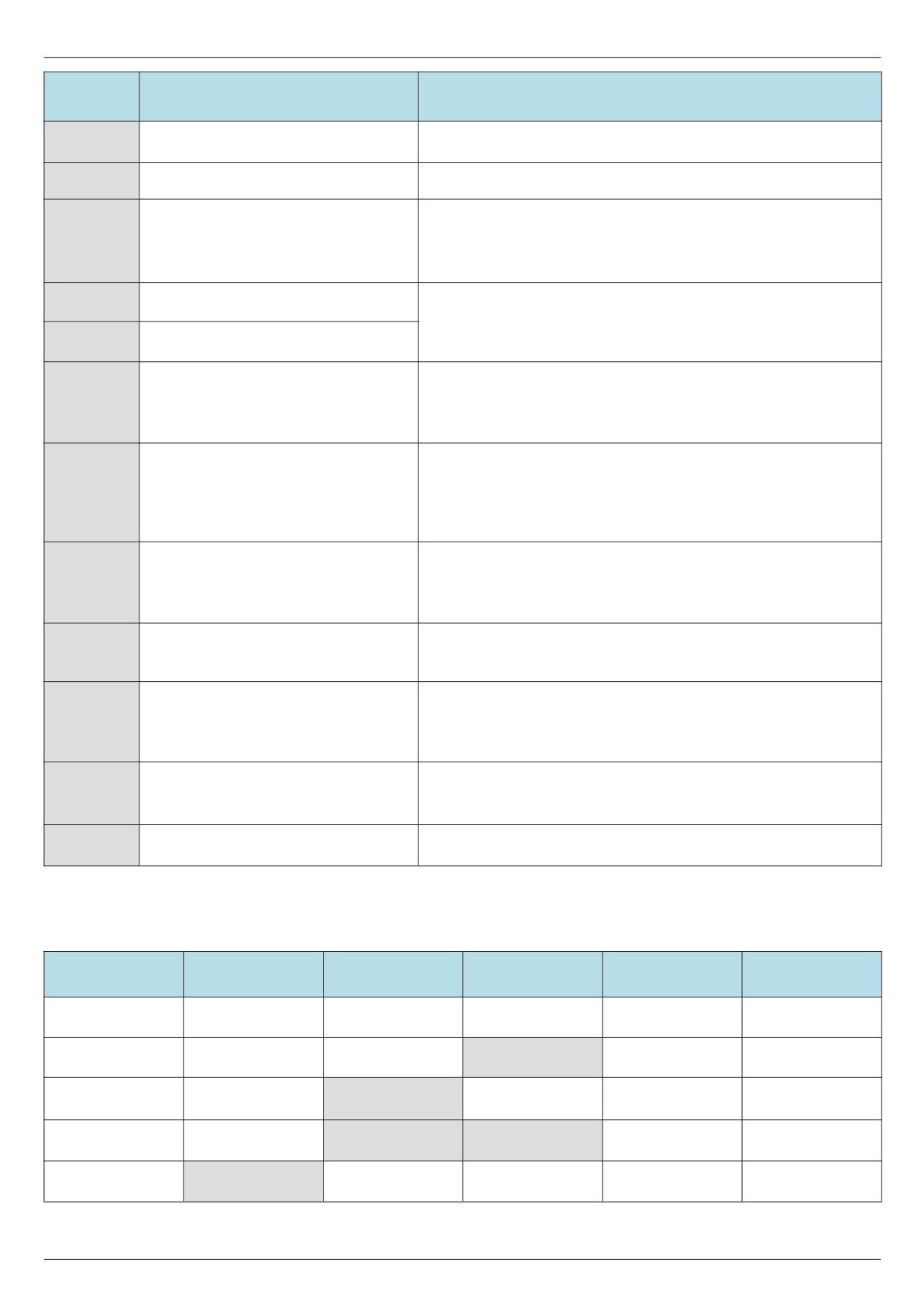
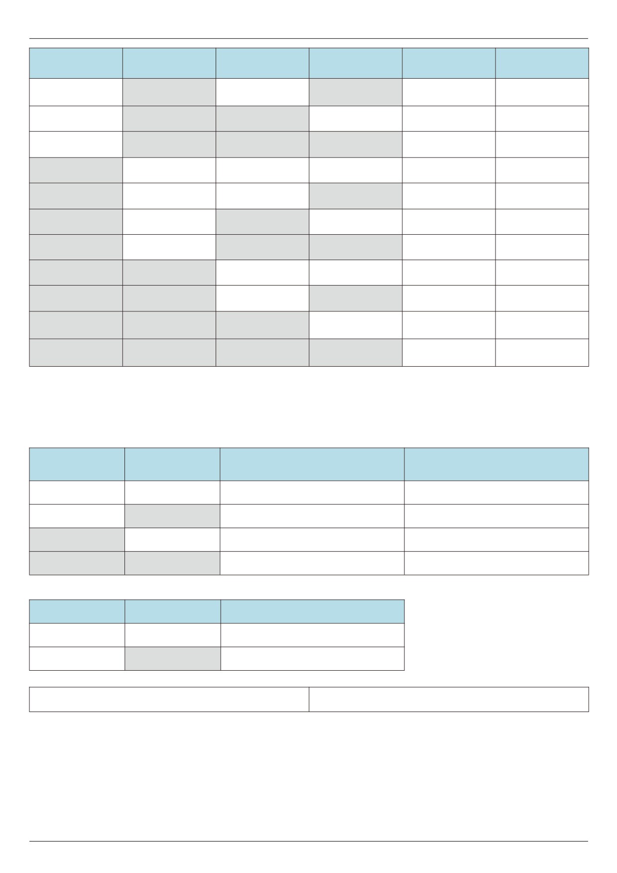
Four multi-segment command terminals can be combined into 16 States, each of which corresponds to 16
command settings. Specific as shown in table 1:
Attached table 1 multi-paragraph instruction function description
Corresponding
K4
K3
K2
K1
Command setting
parameter
Multi - segment
OFF
OFF
OFF
OFF
FC-00
instruction 0
Multi - segment
OFF
OFF
OFF
ON
FC-01
instruction 1
Multi - segment
OFF
OFF
ON
OFF
FC-02
instruction 2
Multi - segment
OFF
OFF
ON
ON
FC-03
instruction 3
Multi - segment
OFF
ON
OFF
OFF
FC-04
instruction 4
- 83 -
Chapter V Description of parameters
Corresponding
K4
K3
K2
K1
Command setting
parameter
Multi - segment
OFF
ON
OFF
ON
FC-05
instruction 5
Multi - segment
OFF
ON
ON
OFF
FC-06
instruction 6
Multi - segment
OFF
ON
ON
ON
FC-07
instruction 7
Multi - segment
ON
OFF
OFF
OFF
FC-08
instruction 8
Multi - segment
ON
OFF
OFF
ON
FC-09
instruction 9
Multi - segment
ON
OFF
ON
OFF
FC-10
instruction 10
Multi - segment
ON
OFF
ON
ON
FC-11
instruction 11
Multi - segment
ON
ON
OFF
OFF
FC-12
instruction 12
Multi - segment
ON
ON
OFF
ON
FC-13
instruction 13
Multi - segment
ON
ON
ON
OFF
FC-14
instruction 14
Multi - segment
ON
ON
ON
ON
FC-15
instruction 15
When the frequency source is selected as multi-segment speed, 100.0
% of the function codes FC - 00 ~ FC -
15
correspond to the maximum frequency F0 - 16. In addition to being a multi-stage speed function, multi-stage
instructions can also be used as a given source of PID or as a voltage source for VF separation control, etc. to meet
the need of switching between different given values.
Table 2 description of terminal function for acceleration and deceleration time selection
Selection of acceleration or
Terminal 2
Terminal 1
Corresponding parameter
deceleration time
OFF
OFF
Acceleration time 1
F0-10, F0-11
OFF
ON
Acceleration time 2
F6-17,F6-18
ON
OFF
Acceleration time 3
F6-19,F6-20
ON
ON
Acceleration time 4
F6-21,F6-22
Attached table 3 motor selection terminal function description
Terminal 2
Terminal 1
Motor selection
OFF
OFF
Motor 1
OFF
ON
Motor 2
F5 - 10 X input terminal filtering time
0.000s~1.000s [0.010s]
Set software filtering time for X terminal status. If the input terminal is easily interfered and causes misoperation in
use, this parameter can be increased to enhance the anti-interference ability.
However, the increase in the filtering time will cause the response of the X terminal to slow down.
- 84 -
Chapter V Description of parameters
F5 - 11 terminal command mode
0~3 [0]
This parameter defines four different ways to control the operation of the frequency inverter through external
terminals.
Note: for convenience of explanation, the X1, X2 and X3 terminals among the X1 - X7 multifunction input
terminals are randomly selected as external terminals. That is, the functions of X1, X2 and X3 terminals are
selected by setting the values of F5 - 00 to F5 - 02. See the setting range of F5 - 00 to F5 - 06 for detailed
function definition.
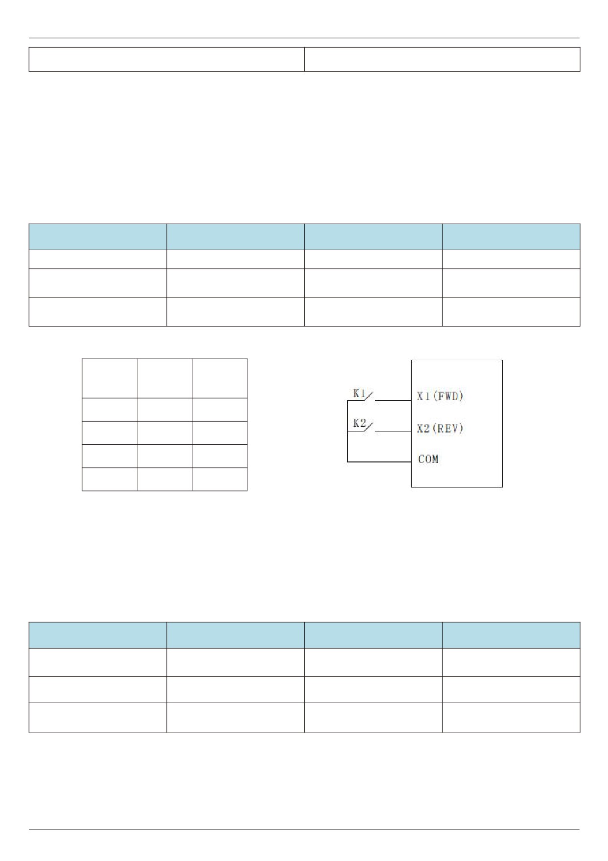
0: two-wire mode 1: this mode is the most commonly used two-wire mode. The forward and reverse rotation of
the motor is determined by terminals x1 and x2.
The function code is set as follows:
Function code
Name
Setting value
Functional description
F5-11
Terminal command mode
0
Two - wire type 1
X1 terminal function
F5-00
1
Forward run ( FWD )
selection
X2 terminal function
F5-01
2
Reverse run (REV)
selection
Operating
K1
K2
instructions
1
0
Forward
0
1
Reversal
1
1
Stop
0
0
Stop
Figure 5 - 12 two-wire modes 1
As shown in the above figure, in this control mode, k1 is closed and the frequency inverter is running forward. K2
closes and reverses, k1 and k2 close or open at the same time, and the frequency inverter stops running.
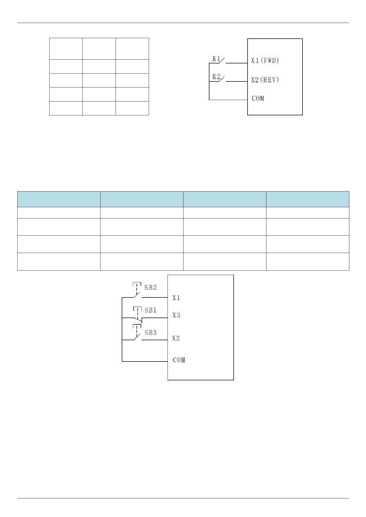
1: two-wire mode 2: with this mode, the x1 terminal function is the operation enable terminal, while the x2 terminal
function determines the direction of operation.
The function code is set as follows:
Function code
Name
Setting value
Functional description
F5-11
Terminal command mode
1
Two - wire type 2
X1 terminal function
F5-00
1
Operation enable
selection
X2 terminal function
Positive and negative
F5-01
2
selection
direction of operation
- 85 -
Chapter V Description of parameters
Operating
K1
K2
instructions
1
0
Forward
1
1
Reversal
0
1
Stop
0
0
Stop
Figure 5 - 12 two-wire modes 2
As shown in the above figure, in this control mode, k2 opens the frequency inverter for forward rotation and k2
closes the frequency inverter for reverse rotation in the k1 closed state. K1 is disconnected and the frequency
inverter stops running.
2: Three-wire control mode 1: this mode X3 is an enable terminal, and the directions are controlled by X1 and X2
respectively.
The function code is set as follows:
Function code
Name
Setting value
Functional description
F5-11
Terminal command mode
2
Three wire type 1
X1 terminal function
F5-00
1
Forward run ( FWD )
selection
X2 terminal function
F5-01
2
Reverse run (REV)
selection
X3 terminal function
Three - wire operation
F5-02
3
selection
control
Figure 5 - 14 three-wire control modes 1
As shown in the above figure, the control mode is in the closed state of SB1 button, press SB2 button to rotate
the frequency inverter forward, press SB3 button to rotate the frequency inverter reversely, and the sb1 button opens
and the frequency inverter stops at the moment. During normal start-up and operation, it is necessary to keep the
SB1 button closed. The commands of SB2 and SB3 buttons will take effect at the closing action edge and the
operating state of the frequency inverter will be subject to the last key action of the three buttons.
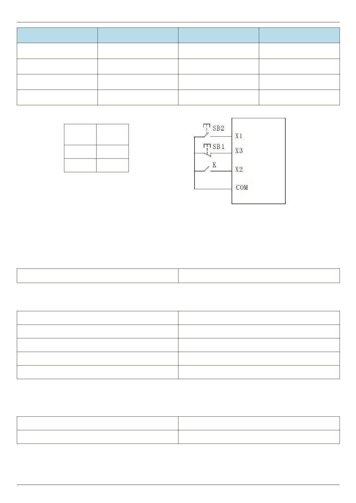
3:3 - wire control mode 2:X3 in this mode is the enable terminal, the operation command is given by X1, and the
direction is given by X1 the status of X2 is determined.
The function code is set as follows
- 86 -
Chapter V Description of parameters
Function code
Name
Setting value
Functional description
F5-11
Terminal command mode
3
Three wire type 2
X1 terminal function
F5-00
1
Operation enable
selection
X2 terminal function
Positive and negative
F5-01
2
selection
direction of operation
X3 terminal function
Three - wire operation
F5-02
3
selection
control
Direction of
K
Operational
movement
0
Forward
Stop
1
Reversal
Reversal
Figure 5 - 15 three-wire control modes 2
As shown in the figure above, the control mode is under the closed state of SB1 button, press the SB2 button
converter to run, K turns off the inverter and K closes the inverter. SB1 button turns off and the frequency inverter
stops immediately. During normal start-up and operation, it is necessary to keep the SB1 button closed, and the SB2
button command will take effect at the edge of the closing action.
F5 - 12 terminal UP/DOWN change rate
0.01Hz/s~65.535Hz/s [1.00Hz/s]
When setting terminal UP/DOWN to adjust the set frequency, the speed of frequency changes, that is, the
amount of frequency change per second.
F5 - 13 PULSE minimum input
0.00kHz~F5-15 [0.00HZ]
F5 - 14 PULSE minimum input corresponding settings
-100.0%~100.0% [0.00HZ]
F5 - 15 PULSE maximum input
F5-13~50.00KHZ [50.00KHZ]
F5 - 16 PULSE maximum input corresponding settings
-100.0%~100.0% [100.0%]
F5 - 17 PULSE filter time
0.00s~10.00s [0.01s]
This set of function codes is used to set the relationship between X5 pulse frequency and corresponding
settings.
The pulse frequency can only be input to the frequency inverter through X5 channel.
F5 - 18 X1 delay time
0.0s~3600.0s [0.00S]
F5 - 19 X2 delay time
0.0s~3600.0s [0.00S]
- 87 -
Chapter V Description of parameters
F5 - 20 X3 delay time
0.0s~3600.0s [0.00S]
Used to set the delay time for the change of X terminal state by the frequency inverter at present, only X1, X2,
X3 have the function of setting the delay time.
F5 - 21 X terminal active mode selection 1
00000~11111 [00000]
Bit: x1 terminal logic set to
0: positive logic
1. Inverse logic
10 bits: X2 terminal valid state setting (0 ~ 1, ditto)
100 bits: X3 terminal valid state setting (0 ~ 1, ditto)
1000 bits: X4 terminal valid state setting (0 ~ 1, ditto)
10,000 bits: X5 terminal valid state setting (0 ~ 1, ditto)
When positive logic is selected, the corresponding X terminal is valid when connected to com, and
disconnection is invalid.
If it is selected as anti-logic valid, the corresponding X terminal will not be valid if it is connected to com, and the
disconnection will be valid.
F5 - 22 X terminal active mode selection 2
00000~11111 [00000]
Bit: X6 terminal logic set to 0: positive logic
1: inverse logic
10 bits: x7 terminal active state setting (0 ~ 1, same as above)
When positive logic is selected, the corresponding X terminal is valid when connected to com, and
disconnection is invalid.
If it is selected as anti-logic valid, the corresponding X terminal will not be valid if it is connected to com, and the
disconnection will be valid.
F5 - 24 AI curve 1 min input
0.00V~F5-26 [0.00V]
F5 - 25 AI curve 1 minimum input corresponding settings
-100.0%~100.0% [0.0%]
F5 - 26 AI curve 1 maximum input
F5-24~10.00V [10.00V]
F5 - 27 AI curve 1 maximum input corresponding settings
-100.0%~100.0% [100.0%]
F5 - 28 AI1 filtering time
0.00s~10.00s [0.10s]
The above function code is used to set the relationship between the analog input voltage and the set value it
represents.
When the voltage of analog input is greater than the set “maximum input" (F5 - 26), the analog voltage is calculated
according to “maximum input". Similarly, when the analog input voltage is less than the set " minimum input" ( F5 -
24 ), it is calculated as the minimum input or 0.0 % based on the setting of " AI is lower than the minimum input
setting selection" ( F5 - 40 ).
When the analog input is a current input, 1ma current is equivalent to 0.5v voltage.
AI1 input filtering time is used to set the software filtering time of AI1. When the analog quantity in the field is
easily interfered, please increase the filtering time to stabilize the detected analog quantity. However, the larger the
filtering time is, the slower the response speed to the analog quantity detection will be. How to set it needs to be
weighed according to the actual application situation
In different applications, the meaning of the nominal value corresponding to 100.0 % set by simulation is
different. Please refer to the description of each application section for details.
The following illustrations show two typical settings:
- 88 -