HV480 Series Frequency Inverter. User Manual (Jun 2021 V0.2 version) - page 2
Chapter IV Functional parameters
Function
Factory
Communica
Name
Setting range
code
value
tion address
0: no operation
1: simple static self - tuning
F1-29
Parameter self - tuning
0
F11DH
2: rotational self - tuning
3. advanced static self - tuning
F2 group of first motor vector control parameters
F2-00
ASR_P1
1~100
30
F200H
F2-01
ASR_I1
0.01s~10.00s
0.50s
F201H
Gain switching frequency
F2-02
0.00~F2-05
5.00Hz
F202H
of ASR 1
F2-03
ASR_P2
1~100
20
F203H
F2-04
ASR_I2
0.01s~10.00s
1.00s
F204H
Gain switching frequency
F2-05
F2 - 02 ~ maximum frequency
10.00Hz
F205H
of ASR 2
Vector controlled slip
F2-06
50% - 200%
100%
F206H
gain
Velocity loop filtering
F2-07
0.000~1.000s
0.050s
F207H
time
0: function code F2 - 10 setting
1: AI1
2: AI2
3: AI3
Torque upper limit source
4: X5 pulse
F2-09
under speed control
0
F209H
5: communication given
mode
6: MIN(AI1,AI2)
7: MAX(AI1,AI2)
The full scale of the 1 - 7 option corresponds to
F2 - 10
Numerical setting of
upper limit of torque
F2-10
0.0%
- 200.0%
150.0%
F20AH
under speed control
mode
Selection of weak
0: not enabled
F2-18
magnetic mode in vector
1: deceleration only enabled
0
F212H
mode
2. constant speed and deceleration enable
Over modulation enable
0: not enabled
F2-19
0
F213H
selection
1: enable
Over modulation
F2-20
100: 110%
100
F214H
coefficient
Weak magnetic moment
F2-21
50: 200%
100
F215H
coefficient
- 29 -
Chapter IV Functional parameters
Function
Factory
Communica
Name
Setting range
code
value
tion address
F3 group V/F control parameters
0: straight line V/F
1: multi-segment V/F( F3 - 03 ~ F3 -
08
)
2: square V/F
3: 1.2 Exponentiation V/F
4: 1.4 Exponentiation V/F
F3-00
V/F curve setting
0
F300H
6: 1.6 Exponentiation V/F
8: 1.8 Exponentiation V/F
9: reservations
10: VF complete separation mode
11: VF semi-separation mode
Model
0.0 %: ( automatic torque boost )
F3-01
Torque increase
determina
F301H
0.1%~30.0%
tion
Torque boost cutoff
F3-02
0.00Hz ~ maximum frequency
50.00Hz
F302H
frequency
F3-03
V/F frequency point F0
0.00Hz~F3-05
0.00Hz
F303H
F3-04
V/F voltage point V0
0.0%~100.0%
0.0%
F304H
F3-05
V/F frequency point F1
F3-03~F3-07
0.00Hz
F305H
F3-06
V/F voltage point V1
0.0%~100.0%
0.0%
F306H
F3-07
V/F frequency point F2
F3 - 05 ~ rated frequency of motor ( F1 -
04
)
0.00Hz
F307H
F3-08
V/F voltage point V2
0.0%~100.0%
0.0%
F308H
V/F slip compensation
F3-09
0.0%~200.0%
0.0%
F309H
gain
F3-10
V/F over-excitation gain
0~200
64
F30AH
Model
V/F oscillation
F3-11
0~100
determina
F30BH
suppression gain
tion
Oscillation suppression
F3-12
0~4
3
F30CH
gain mode
0: numerical setting ( F3 - 14 )
1: AI1
2: AI2
3: AI3
Voltage selection for V/F
4: PULSE pulse setting ( X5 )
F3-13
0
F30DH
separation
5: multi-segment instruction
6: simple PLC
7: PID
8: communication given note: 100.0
%
corresponding motor rated voltage
V/F separated voltage
F3-14
0V ~ rated voltage of motor
0V
F30EH
number word setting
0.0s~1000.0s
V/F separation voltage
F3-15
Note: indicates the time when 0v changes to the
0.0s
F30FH
acceleration time
rated voltage of the motor
- 30 -
Chapter IV Functional parameters
Function
Factory
Communica
Name
Setting range
code
value
tion address
0.0s~1000.0s
V/F separation voltage
F3-16
Note: indicates the time when 0v changes to the
0.0s
F310H
deceleration time
rated voltage of the motor
0: frequency / voltage independently reduced to
V/F separation shutdown
0
F3-17
0
F311H
option
1: the frequency decreases again after the
voltage decreases to 0
- 31 -
Chapter IV Functional parameters
Function
Factory
Communica
Name
Setting range
code
value
tion address
F4 group output terminals
FM terminal output mode
0: pulse output
F4-00
0
F400H
selection
1. switch output
0: no output
1: the frequency inverter is running
2: fault output ( fault for free shutdown )
3: frequency level detection FD t1 output
4: frequency arrival
5: zero speed operation ( no output during
FM switch output power
F4-01
shutdown )
0
F401H
selection
6: motor overload pre - alarm
7: frequency inverter overload pre - alarm
8: set the count value to reach
9: specified count value arrives
10: length arrives
11: PLC cycle completed
12: accumulated operating time arrives
13: frequency limit
14: torque limit
15: operational readiness
16: AI1>AI2
Selection of power
17: upper limit frequency reached
function of control panel
18: lower limit frequency reached ( operation
F4-02
2
F402H
relay
related )
(T/A-T/B-T/C)
19: under voltage state output
20: communication settings
21: positioning completed ( reserved )
22: positioning approach ( reserved )
23: zero speed operation in 2 ( output when
shutdown )
24: cumulative power-on time arrives
25: frequency level detection FD T2 output
26: frequency 1 reaches output
27: frequency 2 reaches output
28: current 1 reaches output
29: current 2 reaches output
30: arrive at output regularly
31: AI1 input overrun
32: falling load
33: reverse operation
34: zero current state
35: module temperature reached
36: output current exceeds limit
DO1 output function
37: lower limit frequency reached ( shutdown
F4-04
1
F404H
selection
also output )
38: alarm output ( all faults )
39: motor over temperature pre - alarm
40: the running time has arrived
41: fault output ( fault for free shutdown
And under-voltage does not output )
42: AI1 is lower than lower limit output, lower
limit F4 - 37
43: AI1 above upper limit output, upper limit F4
-
38
44: AI2 is lower than lower limit output, lower
limit F4 - 37
45: AI2 above upper limit output, upper limit F4
-
38
- 32 -
Chapter IV Functional parameters
Function
Factory
Communica
Name
Setting range
code
value
tion address
0: operating frequency
FM pulse output function
F4-06
1: set frequency
0
F406H
selection
2: Output current
3: output torque ( absolute value of torque )
4: output power
5: Output voltage
AO1 output function
6: PULSE input ( 100.0 % corresponding
F4-07
0
F407H
selection
100.0kHz)
7: AI1
8: AI2
9: AI3
10: length
11: remember values
12: communication settings
13: motor speed
AO2 output function
F4-08
14: output current ( 100.0 % corresponding
1
F408H
selection
1000.0A)
15: output voltage ( 100.0 % corresponding
1000.0V)
16: output torque ( actual torque value )
FM pulse output
F4-09
0.01kHz~100.00kHz
50.00kHz
F409H
maximum frequency
AO1 zero offset
F4-10
-100.0%~+100.0%
0.0%
F40AH
coefficient
F4-11
AO1 gain
-10.00~+10.00
1.00
F40BH
AO2 zero offset
F4-12
-100.0%~+100.0%
0.0%
F40CH
coefficient
F4-13
AO2 gain
-10.00~+10.00
1.00
F40DH
Delay time of FM switch
F4-17
0.0s~3600.0s
0.0s
F411H
output
F4-18
Relay 1 output delay time
0.0s~3600.0s
0.0s
F412H
F4-19
Relay 2 output delay time
0.0s~3600.0s
0.0s
F413H
F4-20
DO1 output delay time
0.0s~3600.0s
0.0s
F014H
F4-21
DO2 output delay time
0.0s~3600.0s
0.0s
F015H
0: positive logic
1. reverse logic
Bit: FM
DO output terminal active
F4-22
10 bits: relay 1
00000
F416H
state selection
100 bits: relay 2
1000 bits: DO1
10,000 bits: DO2
Frequency detection
F4-24
0.00Hz ~ maximum frequency
50.00Hz
F418H
value (FDT1)
Frequency detection lag
F4-25
0.0 % ~ 100.0 % ( FDT1 level )
5.0%
F419H
value (FDT1)
- 33 -
Chapter IV Functional parameters
Function
Factory
Communica
Name
Setting range
code
value
tion address
Frequency detection
F4-26
0.00Hz ~ maximum frequency
50.00Hz
F41AH
value ( FDT2 )
Frequency detection lag
F4-27
0.0 % ~ 100.0 % ( FDT2 level )
5.0%
F41BH
value ( FDT2 )
Frequency reaches
F4-28
0.0 % ~ 100.0 % ( maximum frequency )
0.0%
F41CH
detection width
Random arrival
F4-29
0.00Hz ~ maximum frequency
50.00Hz
F41DH
frequency check value 1
Random arrival
F4-30
0.0 % ~ 100.0 % ( maximum frequency )
0.0%
F41EH
frequency detects width 1
Random arrival
F4-31
0.00Hz ~ maximum frequency
50.00Hz
F41FH
frequency check value 2
Random arrival
F4-32
0.0 % ~ 100.0 % ( maximum frequency)
0.0%
F420H
frequency detects width 2
Arbitrarily reaching
F4-33
0.0 % ~ 300.0 % ( rated current of motor )
100.0%
F421H
current 1
The width of current 1 is
F4-34
0.0 % ~ 300.0 % ( rated current of motor )
0.0%
F422H
arbitrarily reach
Arbitrarily reaching
F4-35
0.0 % ~ 300.0 % ( rated current of motor )
100.0%
F423H
current 2
The width of current 2 is
F4-36
0.0 % ~ 300.0 % ( rated current of motor )
0.0%
F424H
arbitrarily reach
AI1 input voltage
F4-37
protection value lower
0.00V~F4-38
3.10V
F425H
limit
AI1 upper limit of input
F4-38
F4-37~10.00V °C
6.80V
F426H
voltage protection value
Module temperature
F4-39
0°C~100°C
75°C
F427H
reached
Zero current detection
0.0% ~ 300.0%
F4-40
5.0%
F428H
level
100.0 % corresponding motor rated current
Zero current detection
F4-41
0.01s~600.00s
0.10s
F429H
delay time
Output current overrun
0.0 % ( no detection )
F4-42
200.0%
F42AH
value
0.1 % ~ 300.0 % ( rated current of motor )
Output current overrun
F4-43
0.00s~600.00s
0.00s
F42BH
detection delay time
F5 group input terminals
0: no function
X1 input terminal function
F5-00
1: forward run FWD or run command
1
F500H
selection
2: reverse operation REV or reverse operation
direction ( note: when set to 1 and 2, it should be
used in conjunction with F5 - 11. for details,
please refer to the description of function code
parameters )
X2 input terminal function
F5-01
3: three-wire operation control
2
F501H
selection
4: Forward jog(FJOG
5: reverse jog (RJOG)
6: terminal UP
- 34 -
Chapter IV Functional parameters
Function
Factory
Communica
Name
Setting range
code
value
tion address
7: terminal DOWN
8: free parking
9: fault reset (RESET)
10: suspension of operation
X3 input terminal function
F5-02
9
F502H
11: external fault normally open input
selection
12: multi-segment command terminal 1
13: multi-segment command terminal 2
14: multi-segment command terminal 3
15: multi-segment command terminal 4
16: acceleration and deceleration time selection
terminal 1
17: acceleration and deceleration time selection
X4 input terminal function
terminal 2
F5-03
12
F503H
selection
18: frequency source switching
19: UP / DOWN setting cleared ( terminal
keyboard )
20: control command switching terminal 1
21: prohibition of acceleration and deceleration
22: PID pause
23: PLC status reset
X5 input terminal function
F5-04
24: frequency swing suspended
13
F504H
selection
25: counter input
26: counter reset
27: length count input
28: length reset
29: torque control prohibited
30: PULSE frequency input ( valid only for X5
)
X6 input terminal function
31: reservations
F5-05
14
F505H
selection
32: direct current brake immediately
33: external fault normally closed input
34: frequency modification enabled
35: the direction of PID action is reversed
36: external parking terminal 1
37: control command switching terminal 2
38: PID integral suspended
39: frequency source X switches to preset
frequency
40: frequency source Y and preset frequency
switch
41: motor selection terminal 1
42: reservations
43: PID parameter switching
X7 input terminal function
44: user-defined failure 1
F5-06
8
F506H
selection
45: user-defined failure 2
46: speed control / torque control switching
47: Emergency stop button
48: External parking terminal 2
49: deceleration DC brake
50: this run time is cleared
51: 2 - wire / 3 - wire switch
53: zero speed function
54: Frequency source switching 2
55: frequency source switch to multi-segment
speed
F5-10
X terminal filtering time
0.000s~1.000s
0.010s
F50AH
0: 2 - wire type 1
1: 2 - wire type 2
F5-11
Terminal command mode
0
F50BH
2: 3 - wire type 1
3: 3 - wire type 2
Terminal UP / DOWN
F5-12
0.001Hz/s~65.535Hz/s
1.00Hz/s
F50CH
change rate
- 35 -
Chapter IV Functional parameters
Function
Factory
Communica
Name
Setting range
code
value
tion address
F5-13
PULSE minimum input
0.00kHz~F5-15
0.00kHz
F50DH
PULSE minimum input
F5-14
-100.0%~100.0%
0.0%
F50EH
correspondence setting
F5-15
PULSE maximum input
F5-13~100.00kHz
50.00kHz
F50FH
PULSE maximum input
F5-16
-100.0%~100.0%
100.0%
F510H
setting
F5-17
PULSE filtering time
0.00s~10.00s
0.10s
F511H
F5-18
X1 delay time
0.0s~3600.0s
0.0s
F512H
F5-19
X2 delay time
0.0s~3600.0s
0.0s
F513H
F5-20
X3 delay time
0.0s~3600.0s
0.0s
F514H
0: active high
1: low level valid
Bit: X1
F5-21
X terminal valid logic 1
10 bits: X2
00000
F515H
10 bits: X3
1000 bits: X4
10,000 bits: X5
0: active high
1: low level valid
F5-22
X terminal valid logic2
00000
F516H
Bit: X6
10 bits: X7
F5-24
AI curve 1 minimum input
0.00V~F5-26
0.00V
F518H
AI curve 1 minimum input
F5-25
-100.0%~+100.0%
0.0%
F519H
corresponding settings
AI curve 1 maximum
F5-26
F5-24~+10.00V
10.00V
F51AH
input
AI curve 1 maximum
F5-27
input corresponding
-100.0%~+100.0%
100.0%
F51BH
setting
F5-28
AI1 filtering time
0.00s~10.00s
0.10s
F51CH
F5-29
AI curve 2 minimum input
0.00V~F5-31
0.00V
F51DH
AI curve 2 minimum input
F5-30
-100.0%~+100.0%
0.0%
F51EH
corresponding settings
AI curve 2 maximum
F5-31
F5-29~+10.00V
10.00V
F51FH
input
AI curve 2 maximum
F5-32
input corresponding
-100.0%~+100.0%
100.0%
F520H
setting
F5-33
AI2 filtering time
0.00s~10.00s
0.10s
F521H
F5-34
AI curve 3 minimum input
-10.00V~F5-36
-10.00V
F522H
- 36 -
Chapter IV Functional parameters
Function
Factory
Communica
Name
Setting range
code
value
tion address
AI curve 3 minimum input
F5-35
-100.0%~+100.0%
-100.0%
F523H
corresponding settings
AI curve 3 maximum
F5-36
F5-34~+10.00V
10.00V
F524H
input
AI curve 3 maximum
F5-37
input corresponding
-100.0%~+100.0%
100.0%
F525H
setting
F5-38
AI3 filtering time
0.00s~10.00s
0.10s
F526H
Bit: AI1 curve selection
1: curve 1 ( 2 points, see F5 - 24 ~ F5 - 28 )
2: curve 2 ( 2 points, see F5 - 29 ~ F5 - 33 )
3: curve 3 ( 2 points, see F5 - 34 ~ F5 - 38 )
F5-39
AI curve selection
321
F527H
4: curve 4 ( 4 points, see F5 - 41 ~ F5 - 48 )
5: curve 5 ( 4 points, see F5 - 49 ~ F5 - 56 )
10 bits: AI2 curve selection, same as above
100 bits: AI3 curve selection, same as above
Bit: AI1 lower than minimum input setting
selection
0: corresponding minimum input setting
AI is lower than the
1:0.0%
F5-40
minimum input setting
0
F528H
10 bits: AI2 is lower than the minimum input
selection
setting selection, same as above
100 bits: AI3 is lower than the minimum input
setting selection, same as above
F5-41
AI curve 4 minimum input
-10.00V~F5-43
0.00V
F529H
AI curve 4 minimum input
F5-42
-100.0%~+100.0%
0.0%
F52AH
corresponding settings
AI curve 4 inflection point
F5-43
F5-41~F5-45
3.00V
F52BH
1 input
AI curve 4 inflection point
F5-44
1 input corresponding
-100.0%~+100.0%
30.0%
F52CH
settings
AI curve 4 inflection point
F5-45
F5-43~F5-47
6.00V
F52DH
2 input
AI curve 4 inflection point
F5-46
2 input corresponding
-100.0%~+100.0%
60.0%
F52EH
settings
AI curve 4 maximum
F5-47
F5-45~+10.00V
10.00V
F52FH
input
AI curve 4 maximum
F5-48
input corresponding
-100.0%~+100.0%
100.0%
F530H
setting
F5-49
AI curve 5 minimum input
-10.00V~F5-51
-10.00V
F531H
AI curve 5 minimum input
F5-50
-100.0%~+100.0%
-100.0%
F532H
corresponding settings
AI curve 5 inflection point
F5-51
F5-49~F5-53
-3.00V
F533H
1 input
AI curve 5 inflection point
F5-52
1 input corresponding
-100.0%~+100.0%
-30.0%
F534H
settings
AI curve 5 inflection point
F5-53
F5-51~F5-55
3.00V
F535H
2 input
AI curve 5 inflection point
F5-54
2 input corresponding
-100.0%~+100.0%
30.0%
F536H
settings
- 37 -
Chapter IV Functional parameters
Function
Factory
Communica
Name
Setting range
code
value
tion address
AI curve 5 maximum
F5-55
F5-53~+10.00V
10.00V
F537H
input
AI curve 5 maximum
F5-56
input corresponding
-100.0%~+100.0%
100.0%
F538H
setting
F5-65
AI1 sets jumping point
-100.0%~100.0%
0.0%
F541H
F5-66
AI1 sets jump amplitude
0.0%~100.0%
0.5%
F542H
F5-67
AI2 sets jumping point
-100.0%~100.0%
0.0%
F543H
F5-68
AI2 sets jump amplitude
0.0%~100.0%
0.5%
F544H
F5-69
AI3 sets jumping point
-100.0%~100.0%
0.0%
F545H
F5-70
AI3 sets jump amplitude
0.0%~100.0%
0.5%
F546H
F5-71
Reserved
Reserved
--
--
F5-72
Reserved
Reserved
--
--
F6 group start-stop control
0: direct startup
F6-00
Starting mode
1: speed tracking restart
0
F600H
2: pre-excitation start - up
0: starting from shutdown frequency
F6-01
Speed tracking mode
1: starting from zero speed
0
F601H
2: starting from the maximum frequency
F6-02
Speed tracking speed
1~100
20
F602H
F6-03
Starting frequency
0.00Hz~10.00Hz
0.00Hz
F603H
F6-04
Start frequency hold time
0.0s~100.0s
0.0s
F604H
Start DC brake current /
F6-05
0%~100%
0%
F605H
pre-excitation current
Dc brake start time / pre -
F6-06
0.0s~100.0s0.
0s
F606H
excitation time
Stop DC brake starting
F6-07
0.00Hz ~ maximum frequency
0.00Hz
F607H
frequency
Waiting time for
F6-08
shutdown, DC braking,
0.0s~100.0s
0.0s
F608H
etc
F6-09
Stop DC brake current
0% - 100%
0%
F609H
F6-10
Stop DC braking time
0.0s~100.0s
0.0s
F60AH
F6-11
Brake usage rate
0%~100%
100%
F60BH
F6-13
JOG frequency
0.00Hz ~ maximum frequency
2.00Hz
F60DH
F6-14
JOG acceleration time
0.0s~6500.0s
20.0s
F60EH
F6-15
JOG deceleration time
0.0s~6500.0s
20.0s
F60FH
Terminal JOG takes
0: invalid
F6-16
0
F610H
precedence
1: valid
Model
F6-17
Acceleration time 2
0.0s~6500.0s
determina
F611H
tion
- 38 -
Chapter IV Functional parameters
Function
Factory
Communica
Name
Setting range
code
value
tion address
Model
F6-18
Deceleration time 2
0s~6500.0s
determina
F612H
tion
Model
F6-19
Acceleration time 3
0s~6500.0s
determina
F613H
tion
Model
F6-20
Deceleration time 3
0s~6500.0s
determina
F614H
tion
Model
F6-21
Acceleration time 4
0s~6500.0s
determina
F615H
tion
Model
F6-22
Deceleration time 4
determina
F616H
tion
Acceleration and
0: linear acceleration and deceleration
F6-23
0
F617H
deceleration mode
1: S curve acceleration and deceleration
Proportion of time at start
F6-24
0.0%~(100.0%-F6-25)
30.0%
F618H
of S curve
Proportion of time at end
F6-25
0.0%~(100.0%-F6-24)
30.0%
F619H
of S curve
Acceleration time 1 and
F6-26
acceleration time 2
0.00Hz ~ maximum frequency
0.00Hz
F61AH
switching frequency point
Deceleration time 1 and
F6-27
deceleration time 2
0.00Hz ~ maximum frequency
0.00Hz
F61BH
switching frequency point
F7 group torque control parameters
Speed / torque control
0: Speed control
F7-00
0
F700H
mode selection
1: torque control
0: number setting 1 ( F7 - 03 )
1: AI1
2: AI2
3: AI3
Torque setting and
4: PULSE pulse
F7-01
source selection under
0
F701H
5: communication given
torque control mode
6: MIN (AI1,AI2)
7: MAX (AI1,AI2)
( full scale of option 1 - 7, corresponding to F7
-
03 digital setting )
Small torque stop
F7-02
-50.0% ~ 50.0%
0.0%
F702H
compensation
Torque number word
F7-03
setting in torque control
-200.0% ~ 200.0%
150.0%
F703H
mode
Torque control speed
0: set by F7 - 05 and F7 - 06
F7-04
0
F704H
limit source
1: set by F0 - 03 frequency source.
Torque control forward
F7-05
0.00Hz ~ maximum frequency
50.00Hz
F705H
speed limit
Torque control reverse
F7-06
0.00Hz ~ maximum frequency
50.00Hz
F706H
speed limit
F7-07
Torque rise filtering time
0.00s~650.00s
0.00s
F707H
F7-08
Torque drop filtering time
0.00s~650.00s
0.00s
F708H
Torque control frequency
F7-09
0.00s~6500.0s
20.0s
F709H
rise time
Torque control frequency
F7-10
0.00s~6500.0s
20.0s
F70AH
drop time
Coefficient of friction
F7-11
0.0~100.0%
0.0%
F70BH
compensation
Friction compensation
F7-10
0.00s~100.0s
3.0s
F70CH
time
- 39 -
Chapter IV Functional parameters
Function
Factory
Communica
Name
Setting range
code
value
tion address
F8 group auxiliary function
Set the cumulative
F8-00
0h~65000h
0h
F800H
power-up time
Set the cumulative run
F8-01
0h~65000h
0h
F801H
time
0: invalid
F8-04
Timing function selection
0
F804H
1: valid
0: F8 - 06 settings
1: AI1
F8-05
Timing run time selection
0
F805H
2: AI2
3: AI3 analog input range corresponds to F8
-
06
F8-06
Timing run time
0.0Min~6500.0Min
0.0Min
F806H
This run is set at the
F8-07
0.0~6500.0 minutes
0.0Min
F807H
arrival time
F8-08
Hopping frequency 1
0.00Hz ~ maximum frequency
0.00Hz
F808H
F8-09
Hopping frequency 2
0.00Hz ~ maximum frequency
0.00Hz
F809H
F8-10
Hopping frequency 3
0.00Hz ~ maximum frequency
0.00Hz
F80AH
F8-11
Hopping frequency 4
0.00Hz ~ maximum frequency
0.00Hz
F80BH
Amplitude of hopping
F8-12
0.00Hz ~ maximum frequency
0.01Hz
F80CH
frequency
Whether the jump
frequency valid during
0: invalid
F8-13
0
F80DH
acceleration and
1: valid
deceleration
F8-14
Wakeup frequency
( F8 - 16 ) -the maximum frequency ( F0
-
16
)
0.00Hz
F80EH
F8-15
Wake - up and delay time
0.0s~6500.0s
0.0s
F80FH
F8-16
Sleep frequency
0.00Hz ~ wakeup frequency ( F8 - 14 )
0.00Hz
F810H
F8-17
Sleep delay time
0.0s~6500.0s
0.0s
F811H
Output power correction
F8-18
0.00%
- 200.0%
100.0%
F812H
factor
Selection of
0: invalid
F8-19
instantaneous outage
1: deceleration
0
F813H
action
2: slow down and shut down
Momentary stop action
F8-20
suspends judgment of
80.0%~100.0%
90.0%
F814H
cutoff voltage
Judging time of
F8-21
instantaneous power
0.00s~100.00s
0.50s
F815H
failure voltage rising
- 40 -
Chapter IV Functional parameters
Function
Factory
Communica
Name
Setting range
code
value
tion address
Instantaneous power
F8-22
failure action judges OFF
60.0 % ~ 100.0 % ( standard bus voltage )
80.0%
F816H
voltage
Pendulum frequency
0: relative to center frequency
F8-23
0
F817H
setting mode
1: relative to maximum frequency
F8-24
Swing amplitude
0.0% ~ 100.0%
0.0%
F818H
Amplitude of sudden
F8-25
0.0% ~ 50.0%
0.0%
F819H
jump frequency
F8-26
Frequency swing period
0.1s~3000.0s
10.0s
F81AH
Rise time of triangular
F8-27
wave of pendulum
0.1% ~ 100.0%
50.0%
F81BH
frequency
F8-28
Set length
0m~65535m
1000m
F81CH
F8-29
Actual length
0m~65535m
0m
F81DH
Number of pulses per
F8-30
0.1~6553.5
100.0
F81EH
meter
F8-31
Set the count value
1~65535
1000
F81FH
F8-32
Specify count value
1~65535
1000
F820H
F9 group failure and protection
Motor overload protection
0: prohibited
F9-00
1
F900H
selection
1: allowed
Motor overload protection
F9-01
0.20~10.00
1.00
F901H
gain
Motor overload early
F9-02
50% ~ 100%
80%
F902H
warning coefficient
F9-03
Over voltage stall gain
0~100
0
F903H
Over voltage stall
F9-04
120% ~ 150%
130%
F904H
protection voltage
F9-05
Over - loss rate gain
0~100
20
F905H
Over current protection
F9-06
100% ~ 200%
150%
F906H
current
Selection of short circuit
0: invalid
F9-07
protection between
1
F907H
1: valid
power-on and ground
Does the under voltage
0: auto reset
F9-08
0
F908H
fault reset automatically
1: not automatically reset
Number of automatic
F9-09
0~20
0
F909H
fault resets
Fault DO action selection
0: no action
F9-10
during automatic fault
0
F90AH
1: action
reset period
Time between automatic
F9-11
0.1s~100.0s
1.0s
F90BH
fault reset
Bit: input phase loss protection selection
Input phase missing \
10 bits: contactor pull-in protection selection
F9-12
contactor suction
11
F90CH
0: prohibited
protection selection
1: allowed
Output phase - missing
0: prohibited
F9-13
1
F90DH
protection selection
1: allowed
- 41 -
Chapter IV Functional parameters
Function
Factory
Communica
Name
Setting range
code
value
tion address
Bit: motor overload ( OL2 )
0: free parking
1: shut down according to shutdown method
Fault protection action
2. continue running
F9-14
00000
F90EH
option 1
10 bits: input phase missing ( IPL )
100 bits: output phase missing (OPL)
1000 bits: external fault ( ETF )
10,000 bits: communication abnormality (COF)
Bit:
0: free parking
10 bits: abnormal reading and writing of function
Fault protection action
code (E2F)
F9-15
00000
F90FH
option 2
0: free parking
1: shut down according to shutdown method
100 bits: reserved
10,000 bits: running time arrival (rtAF)
Bit: user-defined fault 1 ( UEF1 )
0: free parking
1: shut down according to shutdown method
2: continue running
10 bits: user-defined fault 2 ( UEF2 )
0: free parking
1: shut down according to shutdown method
2: continue to run
100 bits: power on time (UTF)
0: free parking
1: shut down according to the shutdown party
Fault protection action
2: continue to run
F9-16
00000
F910H
option 3
1000 bits: OFF load(LIF)
0: free parking
1: slow down and stop
2: Jump to 7 % of the rated frequency of the
motor to continue running directly, and
automatically return when the load is not OFF
loaded
10,000 bits: when running PID feedback loss
(PIDF)
0: free parking
1: shut down according to shutdown method
2: continue running
Bit: excessive speed deviation ( DEU )
0: free parking
Fault protection action
1: shut down according to shutdown method
F9-17
00000
F911H
option 4
2: continue to run for
10 bits: motor over speed ( OSF )
100 bits: initial position error ( poF )
0: run at current operating frequency
Continue operating
1: run at the set frequency
F9-21
frequency selection in
2: run at the upper limit frequency
0
F915H
case of failure
3: the following limited frequency operation
4: run at abnormal standby frequency
Abnormal standby
0.0 %~100.0 % ( 100.0 % corresponding to the
F9-22
100.0%
F916H
frequency
maximum frequency F0 - 16 )
0: none
F9-23
Motor sensor type
1: PT100
0
F917H
2: PT1000
Motor overheating
F9-24
0°C~200°C
110
F918H
threshold
Motor overheating
F9-25
0°C~200°C
90
F919H
warning threshold
- 42 -
Chapter IV Functional parameters
Function
Factory
Communica
Name
Setting range
code
value
tion address
Off - load protection
0: invalid
F9-26
0
F91AH
option
1: valid
F9-27
Load shedding test level
0.0~100.0%
10.0%
F91BH
F9-28
Off loading test time
0.0~60.0s
1.0s
F91CH
Over - speed detection
F9-30
0.0 % ~ 50.0 % (the maximum frequency )
20.0%
F91EH
value
0.0s: not tested
F9-31
Over - speed test time
1.0s
F91FH
0.1~60.0s
Excessive speed
F9-32
0.0 % ~ 50.0 % (the maximum frequency )
20.0%
F920H
deviation test value
Excessive speed
0.0s: not tested
F9-33
5.0s
F921H
deviation inspection time
0.1~60.0s
FA group PID function
0: FA - 01 settings
1: AI1
2: AI2
FA-00
PID given source
3: AI3
0
FA00H
4: PULSE pulse setting ( X5 )
5: communication given
6: multi-segment instruction given
FA-01
PID value given
0.0%
- 100.0%
50.0%
FA01H
0: AI1
1: AI2
2: AI3
3: AI1-AI2
FA-02
PID feedback source
4: PULSE pulse setting ( X5
)
0
FA02H
5: communication given
6: AI1+AI2
7: MAX (|AI1|, |AI2|)
8: MIN (|AI1|, |AI2|)
0: positive effect
FA-03
PID direction of action
0
FA03H
1: reaction
PID given feedback
FA-04
10~65535
1000
FA04H
range
FA-05
Proportional gain Kp
0.0~100.0
20.0
FA05H
FA-06
Integration time Ti
0.01s~10.00s
2.00s
FA06H
FA-07
Differential time Td
0.000s~10.000s
0.000s
FA07H
PID inversion cutoff
FA-08
0.00 ~ maximum frequency
0.00Hz
FA08H
frequency
FA-09
PID deviation limit
0.0%~100.0%
0.0%
FA09H
FA-10
PID differential limiting
0.00%~100.00%
0.10%
FA0AH
FA-11
PID given change time
0.00~650.00s
0.00s
FA0BH
PID feedback filtering
FA-12
0.00~60.00s
0.00s
FA0CH
time
FA-13
PID output filtering time
0.00~60.00s
0.00s
FA0DH
FA-15
Proportional gain Kp
20.0
FA0FH
- 43 -
Chapter IV Functional parameters
Function
Factory
Communica
Name
Setting range
code
value
tion address
FA-16
Integration time Ti
0.01s~10.00s
2.00s
FA10H
FA-17
Differential time Td
0.000s~10.000s
0.000s
FA11H
0: do not switch
1: switch through X terminal
PID parameter switching
FA-18
2: switch automatically according to deviation
0
FA12H
condition
3: automatically switch according to operating
frequency
Deviation of PID
FA-19
0.0%~FA-20
20.0%
FA13H
parameter switching
PID parameter switching
FA-20
FA-19~100.0%
80.0%
FA14H
offset 2
FA-21
Initial PID value
0.0%~100.0%
0.0%
FA15H
Initial PID value holding
FA-22
0.00~650.00s
0.00s
FA16H
time
Positive maximum of two
FA-23
0.00%~100.00%
1.00%
FA17H
output deviations
Maximum reverse output
FA-24
0.00%~100.00%
1.00%
FA18H
deviation for two times
Bit: integral separation
0: invalid
1: valid
FA-25
PID integral attribute
00
FA19H
10 bits: stop integrating after output to limit value
0: continue integrating
1: stop points
PID feedback missing
0.0 %: loss of feedback without judgment
FA-26
0.0%
FA1AH
test value
0.1%
- 100.0%
PID feedback loss
FA-27
0.0s~20.0s
0.0s
FA1BH
detection time
0: stop without calculation
FA-28
PID shutdown operation
0
FA1CH
1: calculation during shutdown
0: do not wake up under pressure
FA-29
Stress wake-up option
0
FA1DH
1: wake up under pressure
Percentage of wake-up
FA-30
50%~1000%
80.0%
FA1EH
pressure
Pressure wake-up delay
FA-31
0.0~6000.0s
1.0
FA1FH
time
Percentage of dormant
FA-32
0: 100.0%
100.0%
FA20H
pressure
Pressure sleep delay
FA-33
0.0~6000.0s
60.0S
FA21H
time
FB group second group motor parameters
Model
Rated power of
FB-01
0.1kW~6553.5kW
determina
FB01H
asynchronous motor
tion
Model
FB-02
Rated voltage of motor
1V~2000V
determina
FB02H
tion
- 44 -
Chapter IV Functional parameters
Function
Factory
Communica
Name
Setting range
code
value
tion address
0.01A ~ 655.35A ( frequency inverter power ≤
Model
FB-03
Rated current of motor
55kW ) 0.1A ~ 6553.5A ( frequency inverter
determina
FB03H
work rate > 55kW )
tion
Model
FB-04
Rated frequency of motor
0.01Hz ~ maximum frequency
determina
FB04H
tion
Model
FB-05
Rated speed of motor
1rpm~65535rpm
determina
FB05H
tion
0.001~65.535
Model
Stator resistance of
FB-06
( frequency inverter power ≤ 55kW) 0.0001 ~
determina
FB06H
asynchronous motor
6.5535
( frequency inverter power > 55kW )
tion
0.001~65.535
Model
Rotor resistance of
FB-07
( frequency inverter power ≤ 55kW) 0.0001 ~
determina
FB07H
asynchronous motor
6.5535
( frequency inverter power > 55kW )
tion
0.01 mH ~ 655.35 mH( frequency inverter power
Model
Induction motor leakage
FB-08
≤ 55kW) 0.001 mH ~ 65.535 mH ( frequency
determina
FB08H
reactance
inverter power > 55kW )
tion
Mutual inductance
0.1 mH ~ 6553.5 mH( frequency inverter power
Model
FB-09
reactance of
≤ 55kW) 0.01 mH ~ 655.35 mH ( frequency
determina
FB09H
asynchronous motor
inverter power > 55kW )
tion
0.01A~FB-
Model
Asynchronous motor
FB-10
03(frequency inverter power ≤ 55kW)0.1A~FB
determina
FB0AH
no-load current
- 03
( frequency inverter power > 55kW )
tion
0: no operation
FB-29
Tuning selection
1: asynchronous machine static tuning
0
FB1DH
2. asynchronous machine fully tuned
Velocity loop proportional
FB-38
1~100
30
FB26H
gain KP1
Speed loop integral gain
FB-39
0.01s~10.0s
0.50s
FB27H
KI1
FB-40
Switching frequency 1
0.00~FB-43
5.00Hz
FB28H
Velocity loop proportional
FB-41
1~100
20
FB29H
gain KP2
Speed loop integral gain
FB-42
0.01s~10.00s
1.00s
FB2AH
KI2
FB-43
Switching frequency 2
FB-40~maximum frequency
10.00Hz
FB2BH
FB-44
Vector controlled slip gain
50%~200%
100%
FB2CH
FB-45
SVC torque filter constant
00~31
0.000s
FB2DH
- 45 -
Chapter IV Functional parameters
Function
Factory
Communica
Name
Setting range
code
value
tion address
0: FB - 48 settings
1: AI1
2: AI2
Torque upper limit source
3: AI3
FB-47
under speed control
4: PULSE pulse
0
FB2FH
mode
5: communication given
6: MIN (AI1,AI2)
7: MAX (AI1,AI2)1-
Full scale of option 7, corresponding to FB -
Numerical setting of
upper limit of torque
FB-48
0.0%~200.0%
150.0%
FB30H
under speed control
mode
Excitation regulation
FB-51
0~60000
2000
FB33H
proportional gain
Excitation regulation
FB-52
0~60000
1300
FB34H
integral gain
Torque adjusting
FB-53
0~60000
2000
FB35H
proportional gain
Torque adjusting integral
FB-54
0~60000
1300
FB36H
gain
Bit: integral separation
Integral property of
FB-55
0: invalid
0
FB37H
velocity loop
1: valid
0: no PG open loop vector control 1
Second motor control
FB-61
1: no PG open loop vector control 2
0
FB3DH
mode
2: V/F control
0: same as 1st motor
Selection between
1: acceleration and deceleration time
1
FB-62
acceleration and
2: acceleration and deceleration time
2
0
FB3EH
deceleration of 2nd motor
3: acceleration and deceleration time
3
4: acceleration and deceleration time
4
Model
Second motor torque
0.0 %: automatic torque increase
FB-63
determina
FB3FH
boost
0.1%~30.0%
tion
Model
Second motor oscillation
FB-65
0~100
determina
FB41H
suppression gain
tion
FC group multi-segment instruction, simple PLC
Multi - segment
FC-00
-100.0%~100.0%
0.0%
FC00H
instruction 0
Multi - segment
FC-01
-100.0%~100.0%
0.0%
FC01H
instruction 1
Multi - segment
FC-02
-100.0%~100.0%
0.0%
FC02H
instruction 2
Multi - segment
FC-03
-100.0%~100.0%
0.0%
FC03H
instruction 3
Multi - segment
FC-04
-100.0%~100.0%
0.0%
FC04H
instruction 4
Multi - segment
FC-05
-100.0%~100.0%
0.0%
FC05H
instruction 5
Multi - segment
FC-06
-100.0%~100.0%
0.0%
FC06H
instruction 6
Multi - segment
FC-07
-100.0%~100.0%
0.0%
FC07H
instruction 7
- 46 -
Chapter IV Functional parameters
Function
Factory
Communica
Name
Setting range
code
value
tion address
Multi - segment
FC-08
-100.0%~100.0%
0.0%
FC08H
instruction 8
Multi - segment
FC-09
-100.0%~100.0%
0.0%
FC09H
instruction 9
Multi - segment
FC-10
-100.0%~100.0%
0.0%
FC0AH
instruction 10
Multi - segment
FC-11
-100.0%~100.0%
0.0%
FC0BH
instruction 11
Multi - segment
FC-12
-100.0%~100.0%
0.0%
FC0CH
instruction 12
Multi - segment
FC-13
-100.0%~100.0%
0.0%
FC0DH
instruction 13
Multi - segment
FC-14
-100.0%~100.0%
0.0%
FC0EH
instruction 14
Multi - segment
FC-15
-100.0%~100.0%
0.0%
FC0FH
instruction 15
0: stop after single operation
Simple PLC operation
FC-16
1: maintain final value at end of single run
0
FC10H
mode
2: keep circulating
Bit: power failure memory option
0: no memory when power fails
Simple PLC power failure
1: memory when power fails
FC-17
00
FC11H
memory option
10 bits: stop memory option
0 for shutdown memory
1: stop memory
Simple PLC section 0
FC-18
0.0s(h)~6500.0s(h)
0.0s(h)
FC12H
shipping time
Selection of acceleration
FC-19
and deceleration time for
0~3
0
FC13H
simple PLC section 0
Simple PLC section 1
FC-20
0.0s(h)~6500.0s(h)
0.0s(h)
FC14H
shipping time
Selection of acceleration
FC-21
and deceleration time for
0~3
0
FC15H
simple PLC section 1
Simple PLC section 2
FC-22
0.0s(h)~6500.0s(h)
0.0s(h)
FC16H
shipping time
Selection of acceleration
FC-23
and deceleration time for
0~3
0
FC17H
simple PLC section 2
Simple PLC section 3
FC-24
0.0s(h)~6500.0s(h)
0.0s(h)
FC18H
shipping time
Selection of acceleration
FC-25
and deceleration time for
0~3
0
FC19H
simple PLC section 3
Simple PLC section 4
FC-26
0.0s(h)~6500.0s(h)
0.0s(h)
FC1AH
shipping time
Selection of acceleration
FC-27
and deceleration time for
0~3
0
FC1BH
simple PLC section 4
Simple PLC section 5
FC-28
0.0s(h)~6500.0s(h)
0.0s(h)
FC1CH
shipping time
Selection of acceleration
FC-29
and deceleration time for
0~3
0
FC1DH
simple PLC section 5
- 47 -
Chapter IV Functional parameters
Function
Factory
Communica
Name
Setting range
code
value
tion address
Simple PLC section 6
FC-30
0.0s(h)~6500.0s(h)
0.0s(h)
FC1EH
shipping time
Selection of acceleration
FC-31
and deceleration time for
0~3
0
FC1FH
simple PLC section 6
Simple PLC section 7
FC-32
0.0s(h)~6500.0s(h)
0.0s(h)
FC20H
shipping time
Selection of acceleration
FC-33
and deceleration time for
0~3
0
FC21H
simple PLC section 7
Simple PLC section 8
FC-34
0.0s(h)~6500.0s(h)
0.0s(h)
FC22H
shipping time
Selection of acceleration
FC-35
and deceleration time for
0~3
0
FC23H
simple PLC section 8
Simple PLC section 9
FC-36
0.0s(h)~6500.0s(h)
0.0s(h)
FC24H
shipping time
Selection of acceleration
FC-37
and deceleration time for
0~3
0
FC25H
simple PLC section 9
Simple PLC section 10
FC-38
0.0s(h)~6500.0s(h)
0.0s(h)
FC26H
shipping time
Selection of acceleration
FC-39
and deceleration time for
0~3
0
FC27H
simple PLC section 10
Simple PLC section 11
FC-40
0.0s(h)~6500.0s(h)
0.0s(h)
FC28H
shipping time
Selection of acceleration
FC-41
and deceleration time for
0~3
0
FC29H
simple PLC section 11
Simple PLC section 12
FC-42
0.0s(h)~6500.0s(h)
0.0s(h)
FC2AH
shipping time
Selection of acceleration
FC-43
and deceleration time for
0~3
0
FC2BH
simple PLC section 12
Simple PLC section 13
FC-44
0.0s(h)~6500.0s(h)
0.0s(h)
FC2CH
shipping time
Selection of acceleration
FC-45
and deceleration time for
0~3
0
FC2DH
simple PLC section 13
Simple PLC section 14
FC-46
0.0s(h)~6500.0s(h)
0.0s(h)
FC2EH
shipping time
Selection of acceleration
FC-47
and deceleration time for
0~3
0
FC2FH
simple PLC section 14
Simple PLC section 15
FC-48
0.0s(h)~6500.0s(h)
0.0s(h)
FC30H
shipping time
Selection of acceleration
FC-49
and deceleration time for
0~3
0
FC31H
simple PLC section 15
0: S ( seconds )
FC-50
Simple PLC runtime unit
0
FC32H
1: h ( hours )
- 48 -
Chapter IV Functional parameters
Function
Factory
Communica
Name
Setting range
code
value
tion address
0: given function code FC - 00
1: AI1
2: AI2
Given mode of
3: AI3
FC-51
multi-segment instruction
0
FC33H
4: PULSE pulse
0
5: PID
6: preset frequency ( F0 -09 ) given, UP / DOWN
can be modified
FD group communication parameters
Communication protocol
FD-00
0: MODBUS protocol
0
FD00H
selection
Bit: MODBUS
0: 300 bps
1: 600BPS
2: 1200BPS
3: 2400BPS
Communication baud
FD-01
4: 4800BPS
0005
FD01H
rate
5: 9600BPS
6: 19200BPS
7: 38400BPS
8: 57600BPS
9: 115200BPS
0: no check ( 8 -N-2 )
1: even check ( 8-E-1 )
FD-02
MODBUS data format
0
FD02H
2: odd check ( 8-O-1 )
3: no check ( 8-N-1 )
0: broadcast address
FD-03
Local address
1
FD03H
1~247
MODBUS response
FD-04
0~20ms
2
FD04H
delay
0.0: invalid
FD-05
Communication timeout
0.0
FD05H
0.1~60.0s
MODBUS
Bit: MODBUS
FD-06
communication data
0: non-standard MODBUS protocol
31
FD06H
format
1: standard MODBUS protocol
Discrimination rate of
0: 0.01A
FD-07
communication read
0
FD07H
1: 0.1A
current
Communication setting
0: percentage of maximum frequency
FD-08
0
FD08H
frequency selection
1: set frequency directly
0: send back frame after receiving data
FD-09
Return data selection
0
FD09H
1: do not send back frames after receiving data
FE group user customized function code
FE-00
User function code 0
F0-00
FE00H
FE-01
User function code 1
F0-00
FE01H
F0-00~FH-xx
FE-02
User function code 2
F0-00
FE02H
P0-00~Px-xx
U0-xx~U0-xx
FE-03
User function code 3
F0-00
FE03H
FE-04
User function code 4
F0-00
FE04H
FE-05
User function code 5
F0-00
FE05H
- 49 -
Chapter IV Functional parameters
Function
Factory
Communica
Name
Setting range
code
value
tion address
FE-06
User function code
6
F0-00
FE06H
FE-07
User function code
7
F0-00
FE07H
FE-08
User function code
8
F0-00
FE08H
FE-09
User function code
9
F0-00
FE09H
FE-10
User function code
10
F0-00
FE0AH
FE-11
User function code
11
F0-00
FE0BH
FE-12
User function code
12
F0-00
FE0CH
FE-13
User function code
13
F0-00
FE0DH
FE-14
User function code
14
F0-00
FE0EH
FE-15
User function code
15
F0-00
FE0FH
FE-16
User function code
16
F0-00
FE10H
FE-17
User function code
17
F0-00
FE11H
FE-18
User function code
18
F0-00
FE12H
FE-19
User function code
19
F0-00
FE13H
FE-20
User function code
20
F0-00
FE14H
FE-21
User function code
21
F0-00
FE15H
FE-22
User function code
22
F0-00
FE16H
FE-23
User function code
23
F0-00
FE17H
FE-24
User function code
24
F0-00
FE18H
FE-25
User function code
25
F0-00
FE19H
FE-26
User function code
26
F0-00
FE1AH
FE-27
User function code
27
F0-00
FE1BH
FE-28
User function code
28
F0-00
FE1CH
FE-29
User function code
29
F0-00
FE1DH
FF group performance optimization parameters
Fast current limiting
0: not enabled
FF-04
1
FF04H
enable
1: enable
Under voltage point
FF-06
60.0%~140.0%
100.0%
FF06H
setting
Model
FF-09
Over voltage point setting
200.0V~2200.0V
determina
FF09H
tion
- 50 -
Chapter IV Functional parameters
Function
Factory
Communica
Name
Setting range
code
value
tion address
Over current suppression
FF-10
50%~200.0%
150%
FF0AH
starting current
Over current suppression
0: not suppressed
FF-11
1
FF0BH
enable
1: inhibition enable
Post stall suppression
FF-12
0~100
20
FF0CH
gain
Over current suppression
FF-13
current compensation
50%~200.0%
50%
FF0DH
coefficient
Over voltage suppression
FF-14
650.0V~800.0V
760V
FF0EH
starting voltage
Over voltage suppression
0: not suppressed
FF-15
1
FF0FH
enable
1: inhibition enable
Over voltage suppression
FF-16
0~100
30
FF10H
frequency gain
Over voltage suppression
FF-17
0~100
30
FF11H
voltage gain
Over voltage suppression
FF-18
maximum rise limit
0~50Hz
5Hz
FF12H
frequency
Slip compensation
FF-19
0.1~10.0
0.5
FF13H
coefficient
Automatic frequency up
0: not enabled
FF-20
0
FF14H
enable
1: enable
Minimum electric torque
FF-21
10~100
50
FF15H
current
Maximum generating
FF-22
10~100
20
FF16H
torque current
Automatic frequency
FF-23
0~100
50
FF17H
increase KP
Automatic frequency
FF-24
0~100
50
FF18H
increase KI
Rotational speed tracking
FF-26
0~1000
500
FF1AH
proportional gain KP
Rotational speed tracking
FF-27
0~1000
800
FF1BH
integral gain KI
Rotational speed tracking
FF-28
30~200
100
FF1CH
target current
Lower limit of rotational
FF-29
10~100
30
FF1DH
speed tracking current
Rotational speed tracking
FF-30
0.5~30s
1.1s
FF1EH
voltage rise time
FF-31
Demagnetization time
0.00~5.00s
1.00s
FF1FH
Starting voltage of brake
FF-32
650~800
690V
FF20H
unit
FF-33
Instantaneous stop gain
0~100
40
FF21H
FF-34
Instant stop gain
0~100
30
FF22H
Deceleration time for
FF-35
0.0~300.0s
5.0
FF23H
momentary stop
0: invalid
Instant stop function
FF-36
1: slow down but do not stop
0
FF24H
selection
2: slow down to stop
Instantaneous stop
FF-37
recovery judgment
80: 100%
85%
FF25H
voltage
Judging time for
instantaneous stop and
FF-38
0.0~100.0s
0.5s
FF26H
non-stop voltage
recovery
Judging time for
FF-39
instantaneous stop and
60%~100%
80%
FF27H
non-stop movement
- 51 -
Chapter IV Functional parameters
Function
Factory
Communica
Name
Setting range
code
value
tion address
E0 group fault record group
0: no fault
1: reservations
2: accelerating over current
3: slow down over current
4: constant speed over current
5. accelerating Over voltage
6: deceleration Over voltage
7: constant speed Over voltage
8: buffer resistance overload
9: under voltage
10: frequency inverter overload
11: motor overload
12: enter missing phase
13: output phase missing
14: module overheating
15: external failure
16: abnormal communication
17: contactor abnormal
18: abnormal current detection
E0-00
First failure type
-
AF00H
19: abnormal motor tuning
20: encoder /PG card exception
21: abnormal reading and writing of parameters
22: abnormal frequency inverter hardware
23: motor short circuit to ground
24: reservations
25: reservations
26: the running time has arrived
27: User - defined fault 1
28: User - defined fault 2
29: Time to power on
30: OFF load
31: loss of PID feedback at runtime
40: fast current limit timeout
41: switch the motor during operation
42: Speed deviation is too large
43: motor over speed
45: motor over temperature
51: incorrect initial position
E0-01
Second failure type
-
AF01H
Third ( most recent )
E0-02
-
AF02H
failure type
Frequency of third ( most
E0-03
-
-
AF03H
recent ) failure
Current at the third ( most
E0-04
-
-
AF04H
recent ) fault
Bus voltage at the third
E0-05
-
AF05H
( most recent ) fault
-
Enter the terminal status
E0-06
for the third ( most
-
-
AF06H
recent ) failure
- 52 -
Chapter IV Functional parameters
Function
Factory
Communica
Name
Setting range
code
value
tion address
Output terminal status at
E0-07
third ( most recent )
-
-
AF07H
failure
frequency inverter status
E0-08
at the third ( most recent )
-
-
AF08H
failure
Power on time for the
E0-09
third ( most recent )
-
-
AF09H
failure
Run time at the third
E0-10
-
-
AF0AH
( most recent ) failure
Frequency at second
E0-13
-
-
AF0DH
failure
E0-14
Current at second failure
-
-
AF0EH
Bus voltage at second
E0-15
-
-
AF0FH
failure
Enter the terminal status
E0-16
-
-
AF10H
during the second failure
Output terminal status at
E0-17
-
-
AF11H
second failure
frequency inverter status
E0-18
-
-
AF12H
at second failure
Power on time for second
E0-19
-
-
AF13H
failure
Run time at second
E0-20
-
-
AF14H
failure
E0-23
Frequency at first failure
-
-
AF17H
E0-24
Current at first failure
-
-
AF18H
E0-25
Bus voltage at first failure
-
-
AF19H
Enter the terminal status
E0-26
when the fault occurs for
-
-
AF1AH
the first time.
Output terminal status at
E0-27
-
-
AF1BH
first failure
frequency inverter status
E0-28
-
-
AF1CH
at first failure
Power on time for first
E0-29
-
-
AF1DH
failure
E0-30
Run time at first failure
-
-
AF1EH
P2
group AIA correction group
Factory
P2-00
AI1 measured voltage 1
-10.00V~10.00V
A200H
correction
Factory
P2-01
AI1 displayed voltage 1
-10.00V~10.00V
A201H
correction
- 53 -
Chapter IV Functional parameters
Function
Factory
Communica
Name
Setting range
code
value
tion address
Factory
P2-02
AI1
measured voltage 2
-10.000V~10.000V
A202H
correction
Factory
P2-03
AI1
displayed voltage 2
-10.000V~10.000V
A203H
correction
Factory
P2-04
AI2
measured voltage 1
-10.000V~10.000V
A204H
correction
Factory
P2-05
AI2
displayed voltage 1
-10.000V~10.000V
A205H
correction
Factory
P2-06
AI2
measured voltage 2
-10.000V~10.000V
A206H
correction
Factory
P2-07
AI2
displayed voltage 2
-10.000V~10.000V
A207H
correction
Factory
P2-08
AI3
measured voltage 1
-10.000V~10.000V
A208H
correction
Factory
P2-09
AI3
displayed voltage 1
-10.000V~10.000V
A209H
correction
Factory
P2-10
AI3
measured voltage 2
-10.000V~10.000V
A20AH
correction
Factory
P2-11
AI3
displayed voltage 2
-10.000V~10.000V
A20BH
correction
- 54 -
Chapter IV Functional parameters
4.2
Summary table of monitoring parameters
Communication
Function code
Name
Minimum unit
address
U0 group basic monitoring parameters
U0-00
Operating frequency ( Hz )
0.01Hz
7000H
U0-01
Set frequency ( Hz )
0.01Hz
7001H
U0-02
Busbar voltage (V)
0.1V
7002H
U0-03
Output voltage (V)
1V
7003H
U0-04
Output current (A)
0.01A
7004H
U0-05
Output power ( kW )
0.1kW
7005H
U0-06
Output torque ( % )
0.1%
7006H
U0-07
X terminal input status
1
7007H
U0-08
Do output state
1
7008H
U0-09
AI1 voltage ( V )
0.01V
7009H
AI2 voltage (V) / current
U0-10
0.01V/0.01mA
700AH
(mA)
U0-11
AI3 voltage (V)
0.01V
700BH
U0-12
count value
1
700CH
U0-13
Length value
1
700DH
U0-14
Load speed display
1
700EH
U0-15
PID setting
1
700FH
U0-16
PID feedback
1
7010H
U0-17
PLC stage
1
7011H
PULSE input pulse
U0-18
0.01kHz
7012H
frequency (Hz)
U0-19
Feedback speed (Hz)
0.01Hz
7013H
U0-20
Remaining operating time
0.1Min
7014H
U0-21
AI1 pre-correction voltage
0.001V
7015H
AI2 voltage before
U0-22
0.001V/0.01mA
7016H
correction (V) / current (mA)
AI3 voltage before
U0-23
0.001V
7017H
correction
U0-24
Linear velocity
1m/Min
7018H
U0-25
Current power-on time
1Min
7019H
U0-26
Current run time
0.1Min
701AH
PULSE input pulse
U0-27
1Hz
701BH
frequency
U0-28
communication set value
0.01%
701CH
- 55 -
Chapter IV Functional parameters
Communication
Function code
Name
Minimum unit
address
U0-30
Main frequency X display
0.01Hz
701EH
Secondary frequency Y
U0-31
0.01Hz
701FH
display
View any memory address
U0-32
1
7020H
values
U0-34
Motor temperature value
1°C
7022H
U0-35
Target torque ( % )
0.1%
7023H
U0-37
Power factor angle
0.1°
7025H
U0-39
VF separates target voltage
1V
7027H
VF separates output
U0-40
1V
7028H
voltage
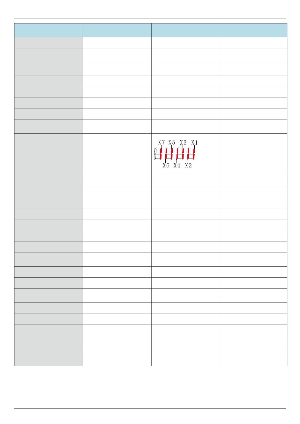
Bright is valid
U0-41
X input status visual display
7029H
Out is invalid
DO input status visual
U0-42
1
702AH
display
U0-45
Fault message
1
702DH
U0-59
Set frequency ( % )
0.01%
703BH
U0-60
Operating frequency ( % )
0.01%
703CH
U0-61
frequency inverter status
1
703DH
U0-62
Current fault code
1
703EH
U0-65
Upper torque limit
0.1%
7041H
frequency inverter module
U0-69
0°C~120°C
7045H
radiator temperature
U0-70
Accumulated operating time
0h~65535h
7046H
U0-71
Cumulative power-on time
0~65535 hours
7047H
Cumulative power
U0-72
0 ~ 65535 degrees
7048H
consumption
U0-73
Product Number
-
7049H
U0-74
Software version number
-
704AH
Rated power of frequency
U0-76
0.1KW
704CH
converter
frequency inverter G/P type
U0-77
1
704DH
machine
Rated voltage of frequency
U0-78
1V
704EH
inverter
- 56 -
Chapter V Description of parameters
Chapter V Description of parameters
In this chapter:
FX-XX
YYYYYY
N1~N2
[D]
(function cod )
(function code name)
(function code range )
(default)
F0 Group basic function group
F0 - 00 menu display selection
0~11 [11]
00: only f group parameters are displayed.
01: display f group and u group parameters.
11: display parameters of group f, group p, and group u.
F0 - 01 motor control mode selection
0~2 [2]
0: no PG open loop vector control 1
Refers to open-loop vector control, which is suitable for common high-performance control occasions. And a
frequency inverter can only drive one electric machine. Such as machine tools, centrifuges, wire drawing machines,
injection molding machines, etc.
1: no PG open loop vector control 2
2: V/F control
It is suitable for occasions where the load requirement is not high, or one frequency inverter drives multiple
motors, such as negative load of fans and pumps. For occasions where one frequency inverter drags multiple motors
Tips:
The motor parameter identification process must be carried out when selecting the vector control mode. Only
accurate motor parameters can give rise to the advantages of vector control. Better performance can be obtained by
adjusting the speed regulator parameter F2 group of function codes.
F0 - 02 Command given way
0~2 [0]
0: operation panel command channel (“LOCAL/REMOT” light goes out);
The run command is controlled by the RUN, STOP/RES keys on the operation panel.
1: terminal command channel (“LOCAL/REMOT” light on);
The multifunctional input terminals FWD, REV, JOGF, JOGR, etc. control the operation command.
2: the communication command channel (“LOCAL/REMOT" light flashes)
Operation command is given by the upper computer through communication.
Write the control command through address 0×2000. See appendix A for the definition of the control command.
- 57 -
Chapter V Description of parameters
F0 - 03 Main frequency source X selection
0~9 [1]
0: Digital setting (no memory when power fails)
The initial value of the set frequency is F0 - 09 " preset frequency". The setting frequency value of the frequency
inverter can be changed through the knob of the keyboard (or up and down of the multi-function input terminal).
When the frequency inverter is powered down and powered on again, the set frequency value returns to F0 - 09
" digital set preset frequency" value.
1: digital setting (power failure memory)
The initial value of the set frequency is F0 - 09 " preset frequency". The setting frequency value of the frequency
inverter can be changed through the knob of the keyboard (or up and down of the multi-function input terminal).When
the frequency inverter is powered down and powered up again, the set frequency is the set frequency at the time of
the last power down, and is memorized through the knob or the correction amount of terminals up and down.
It should be noted that F0 - 26 is “digital set frequency stop memory selection" and F0 - 26 is used to select
whether the frequency correction is memorized or cleared when the frequency inverter is stopped. F0 - 26 is related
to shutdown, not to power-down memory. Attention should be paid in application.
2: AI1
3: AI2
4: AI3
Where:
AI1 is a 0v - 10v voltage type input
AI2 can be a 0v - 10v voltage input or a 4ma - 20ma current input. The j8 jumper on the control panel selects
AI3 can be a 0v - 10v voltage input
The input voltage values of AI1, AI2, and AI3 correspond to the target frequency and can be freely selected by
the user.
HV480 provides 5 groups of correspondence curves, and F5 group function codes are set.
AI is given as frequency, and the voltage / current input corresponds to 100.0 % set, which is the percentage ratio of
F0 - 16 relative to the maximum frequency.
5. Pulse given (X5)
Frequency is given through terminal X5 high speed pulse.
Pulse given signal specification: voltage range 9V~30V, frequency range 0kHz~100kHz. Pulse given can only be
input from the multifunctionality input terminal X5.
The relationship between the X5 terminal input pulse frequency and the corresponding setting is set through
F5-13~F5-17. The corresponding relationship is a linear correspondence of 2 bits. The 100.0 % set corresponding
to the pulse input refers to the percentage of the relative maximum frequency F0 - 16.
6. When selecting a multi-segment instruction
Operation mode for a multi-segment instruction, different combinations of States of the Xi terminal need to be
input through a digital quantity. The corresponding the different set frequency value. HV480 can be provided with 4
multi-segment command terminals (terminal functions 12 - 15). The 16 States of 4 terminals can correspond to any
16 " multi-segment commands" through FC group function codes. The
“multi-segment commands" are the
percentage of the relative maximum frequency F0 - 16.
When digital quantity input X terminal is used as multi-segment command terminal function, corresponding
settings need to be made in F5 group. Please refer to F5 group related function parameter description for details.
7. When the simple PLC
Frequency source is a simple PLC, the operation frequency source of the frequency converter can be switched
between 1 to 16 arbitrary frequency commands. The holding time of 1~16 frequency commands and the respective
acceleration and deceleration time can also be set by the user. For details, please refer to FC group's relevant
instructions.
- 58 -