HV590L Series Frequency Inverter. User Manual (Version: 3.1.14) - page 4
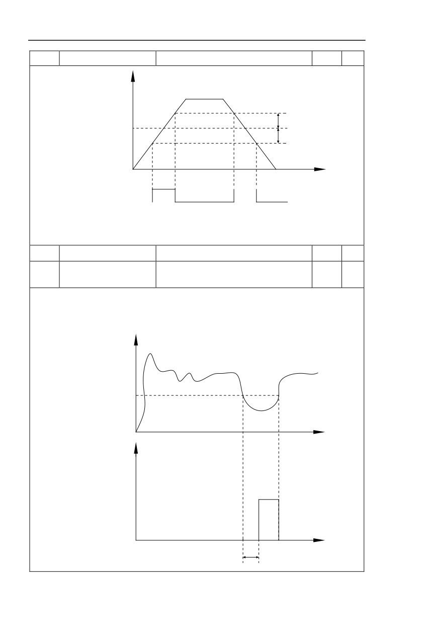
detection range2
Running frequency
Frequency detection range
Random frequency arrival
Frequency detection range
t
ON
ON
Random frequency arrival
detection signal or relay
OFF
OFF
OFF
Fig.5-20 Random frequency arrival detection schematic diagram
When inverter output frequency is within the positive & negative detection range of random frequency
arrival detection value , multi-funtion terminalDO output ON signal.
P8.34
Zero-current detection level
0.0%~300.0%(Motor rated current)
5.0%
☆
Zero-current detection delay
P8.35
0.00s~600.00s
0.10s
☆
time
When inverter output current is less than or equals to zero-current detection level, and the lasting
time exceeds zero-current detection delay time,inverter multi-function terminal DO output DO signal.
Fig.5-21 is schematic diagram of zero-current detection.
Output current
P8.34
t
Zero current
detection signal
ON
t
P8.35
96
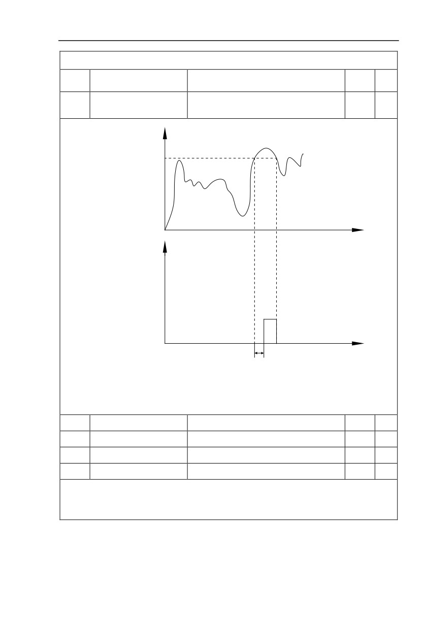
Fig.5-21 Zero-current detection schematic diagram
0.0%(No detection)
P8.36
Output current overlimit value
200.0%
☆
0.1%~300.0%(Motor rated current)
Output current overlimit
P8.37
0.00s~600.00s
0.00s
☆
detection delay time
Output current
P8.36
t
Output current overlimit
detection signal
ON
t
P8.37
Fig.5-22 Output current overlimit detection schematic diagram
When inverter output current is larger than output current overlimit value(P8.36) ,and lasting time
exceeds the software overlimit detection delay time ,inverter multi-function terminalDO output ON signal,
fig.5-22 is schematic diagram of output current overlimit detection.
P8.38
Random currentarrival 1
0.0%~300.0%(Motor rated current)
100.0%
☆
P8.39
Random current arrival range1
0.0%~300.0%(Motor rated current)
0.0%
☆
P8.40
Random currentarrival 2
0.0%~300.0%(Motor rated current)
100.0%
☆
P8.41
Random currentarrival range2
0.0%~300.0%(Motor rated current)
0.0%
☆
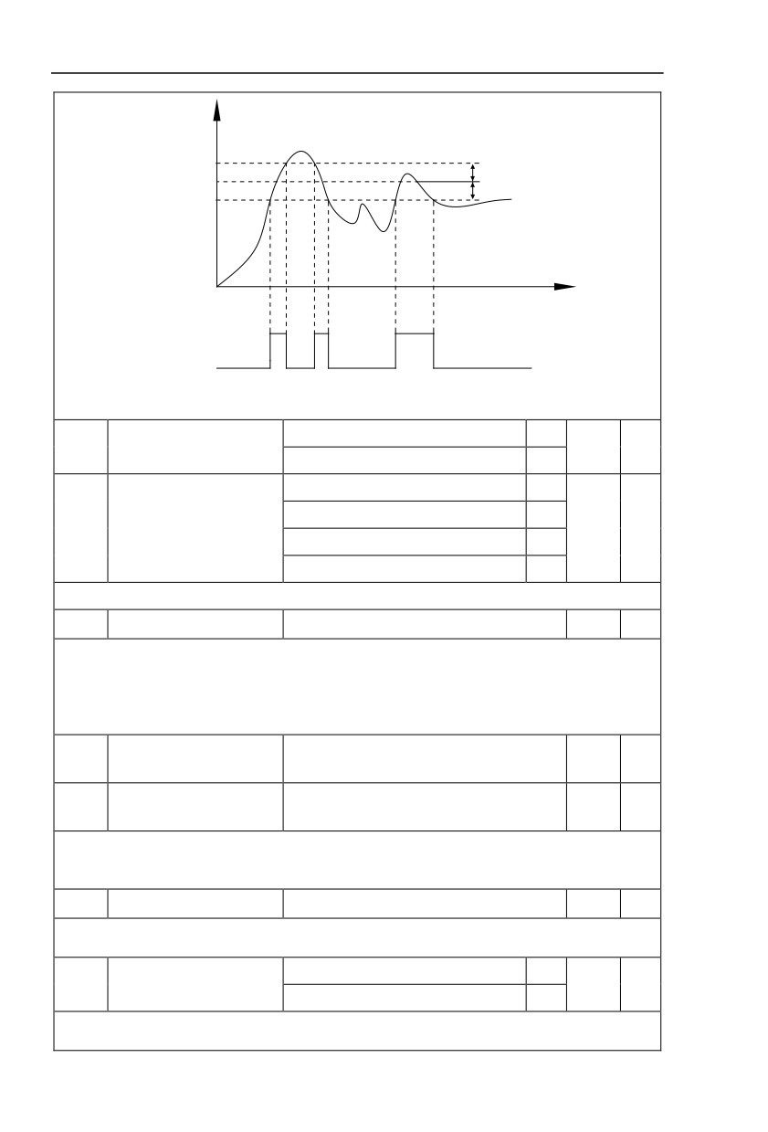
When inverter output current is within the positive & negative detection range of random arrival current
value , multi-funtion terminalDO output ON signal.
HV590L offers two groups of random current arrival range detection parameters ,as shown in fig. 5-23.
97
Output current
Random current arrival range
Random current arrival
Random current arrival range
t
ON
ON
ON
Random current arrival
detection signal or relay
OFF
OFF
OFF
Fig.5-23Random current arrival detection schematic diagram
Invalid
0
P8.42
Timing function selection
0
☆
Valid
1
P8.44 setup
0
AI1
1
P8.43
Running time timing selection
0
☆
AI2
2
AI3(Potentiometer)
3
Analog input range 100% corresponds to P8.44.
P8.44
Timing running time
0.0Min~6500.0Min
0.0Min
☆
This parameter group is used to time inverter running time.
When P8.42 is valid, inverter starts timing. Inverter would automatically stop after reaching the timing
setup , multi-function terminalDO output ON signal.
Each time inverter startup from 0 start the timing, timing surplus running time could be viewed through
U0.20. Timing of the operation time is set through P8.43, P8.44, unit minute.
AI1 input voltage protection
P8.45
0.00V~P8.46
3.10V
☆
value lower limit
AI1 input voltage protection
☆
P8.46
P8.45~10.00V
6.80V
value upper limit
When analog input AI1 is greater than the set of P8.46 or less than that of P8.47, inverter multi-
functionDO output ON signal of “AI1 input overrun” , which indicating if AI1 input voltage is within the setup
range.
P8.47
Module temperature arrival
0.00℃~100℃
75℃
☆
Inverter multi-function terminal DO outputs “module temperature arrival” ON signal when inverter
radiator temperature arrived the set value of P8.47.
Cooling fan runs at motor operation
0
P8.48
Cooling fan control
0
☆
Cooling fan runs after power-on
1
It is used to select cooling fan action mode.
P8.48=0:Cooling fan operates when inverter in running status or radiator temperature over 40℃ in
98
inverter stop status.the fan does not operater when inverter in stopping status and adiator temperature
below 40℃
P8.48=1:Cooling fan is always running after power-on.
Sleep frequency(P8.51) ~maximum frequency
P8.49
Wakeup frequency
0.00Hz
☆
(P0.10)
P8.50
Wakeup delay time
0.0s~6500.0s
0.0s
☆
P8.51
Sleep frequency
0.00Hz~wake-up frequency(P8.49)
0.00Hz
☆
P8.52
Sleep delay time
0.0s~6500.0s
0.0s
☆
This group of function codes are used to realize sleep and wake up function.
During operation:when set frequency is less than or equals to sleep frequency(P8.51), inverter would
step into sleep state and stop after sleep delay time(P8.52).
If inverter is in sleep state and current running command is valid, when set frequency is no less than
P8.49 wake-up frequency, inverter will start to run after P8.50 wake-up delay time.
Generally, please set wake-up frequency no less than sleep frequency. Sleep function and wake-up
function are valid when both wake-up frequency and sleep frequency are set to 0.00 Hz.
When enabling sleep function(frequency source :PID) , PID calculation selection in sleep state is
influenced by function code PA.28(PA.28=1).
P8.53
The running time arrival
0.0Min~6500.0Min
0.0Min
☆
When the running time reached the P8.53 set value, inverter multi-function DO output “Then running
time arrival” ON signal.
5.11 Overload and protection:P9.00-P9.70
Description/
FactoryChange
Code
Setting Range
Keyboard Display
Setting
Limit
Invalid
0
Motoroverload protection
P9.00
1
☆
selection
Valid
1
Motor overload protection
P9.01
0.20~10.00
1.00
☆
gain
P9.00=0: Without motor overload protection function. It is recommended to install a thermal relay
between the motor and the inverter.
P9.00=1: The inverter has overload protection function for the motor according to motor overload
protection inverse time limit curve.
Motor overload protection inverse time limit curve: 220%×(P9.01)× motor rated current,it will report
motor overload fault after it lasts for one minute. When the operating current of the motor reaches the
current of 150%×(P9.01)times the rated current of the motor, it will report motor overload after it lasts 60
minutes.
Users can set value of P9.01 according to the motor actual overload ability.If the parameter is set too
big, it may cause danger of motor overheating damage without inverter fault report.
Motor overload pre-alarm
P9.02
50%~100%
80%
☆
coefficient
This function is used before motor overload fault by giving pre-alarm signal through multi-function
terminalDO.This pre-alarm coefficient is used to determine the warning timing before motor overload
protection. The higher the value,the shorter the warning timing will be.
When the inverter output current is accumulated more than the product of inverse time limit curve with
P9.02,multi-function terminalDO output “Motor overload pre-alarm”ON signal.
99
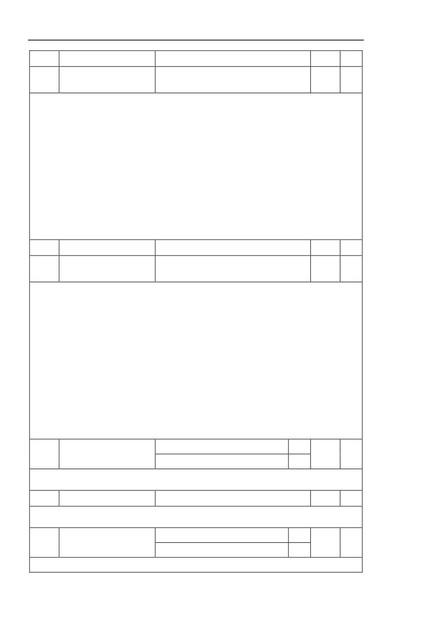
P9.03
Over-voltage stall gain
0(no over-voltage stall)~100
0
☆
Over-voltage stall protection
P9.04
120%~150%(3 phase)
130%
☆
voltage
Over voltagestall : When the output voltageof the inverter reaches setup of over voltage stall
protection voltage (P9.04), if the inverter is running with acceleration speed, it will stop acceleration. When
the inverter is running with constant speed, it will reduce the output frequency. When the inverter is running
with deceleration speed, it will stop deceleration and the operating frequency will not recover normally till
the current is less than the current stall protection current (P9.04).
Over voltage stall protectionvoltage: It selects the protection point for over current stall function.
When the value is exceeded, the inverter starts to execute the over voltage stall protection function. This
value is relative to the percentage of rated voltageof the motor.
Overvoltage stall gain: It adjusts the inverter’s capacity in suppressing the voltage stall. The bigger
the value is, the stronger the capacity is. For the load with small inertia, the value should be small.
Otherwise, the dynamic response of the system would be slow. For the load with large inertia, the value
should be large. Otherwise, the suppressing result will be poor, and over voltage fault may be caused.
When the voltage stall gain is set to 0, the inverter starts to execute the over voltage stall protection
function.
P9.05
Over current stall gain
0~100
20
☆
Over current stall protection
P9.06
100%~200%
170%
☆
current
Over current stall: When the output current of the inverter reaches setup of over current stall
protection current (P9.06), if the inverter is running with acceleration speed, it will stop acceleration. When
the inverter is running with constant speed, it will reduce the output frequency. When the inverter is running
with deceleration speed, it will stop deceleration and the operating frequency will not recover normally till
the current is less than the current stall protection current (P9.06).
Over current stall protection current: It selects the protection point for over current stall function.
When the value is exceeded, the inverter starts to execute the over current stall protection function. This
value is relative to the percentage of rated current of the motor.
Over current stall gain: It adjusts the inverter’s capacity in suppressing the over current stall. The
bigger the value is, the stronger the capacity is. the stronger the capacity is. For the load with small inertia,
the value should be small. Otherwise, the dynamic response of the system would be slow. For the load with
large inertia, the value should be large. Otherwise, the suppressing result will be poor, and over currentfault
may be caused.
When the current stall gain is set to 0, the inverter starts to execute the over voltage stall protection
function.
Ground short circuit protection
Invalid
0
P9.07
1
☆
upon power-on
Valid
1
It determines whether the motor has ground short circuit fault upon power-on. If this function is valid,
the inverter UVW end will output voltage within the period of time after power-on.
P9.09
Fault auto reset times
0~20
0
☆
When the inverter selects fault auto reset, it is used to set the times of auto reset. If this value is
exceeded, the inverter will perform fault protection.
Fault auto reset FAULTDO
No action
0
P9.10
0
☆
selection
Action
1
If inverter has been set of fault auto reset function , P9.10 is used to set if FAULT DO actions or not
100
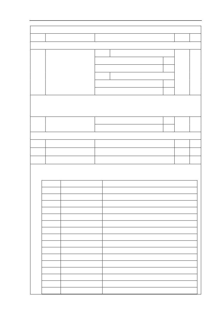
during fault auto reset time.
P9.11
Fault auto reset interval
0.1s~100.0s
1.0s
☆
The waiting time of the inverter from the fault alarm to auto reset.
1bit
Input phase lack protection selection
Forbidden
0
Allowed
1
Input phase lack protection
P9.12
11
☆
selection
10bit
Contactor attracting protection
Forbidden
0
Allowed
1
1bit:It is used to choose whether to protect input phase loss.
10bit:Contactor attracting protection
HV590L series inverter above 132kW (type G) has input phase fault protection function.For the
inverter below 132kW (type P), the input phase fault protection function is invalid at any setup.
Invalid
0
Output phase lack protection
P9.13
1
☆
selection
valid
1
It is used to choose whether to protect output open-phase.
P9.14
The first fault type
0~99
-
●
P9.15
The second fault type
0~99
-
●
P9.16
The latest fault type
0~99
-
●
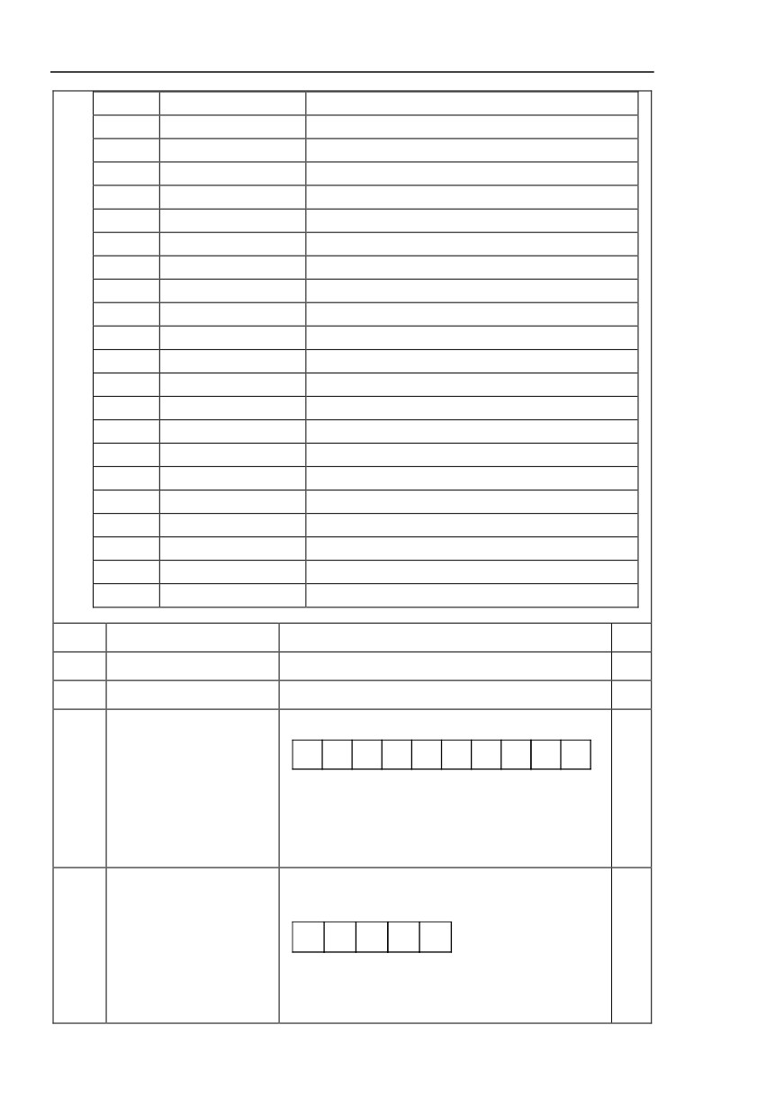
It records the latest 3 fault types for the inverter: 0 means no fault and 1 to 99 correspond to refer to
Chapter 6 for the details.
Table of fault type :
No.
Fault display
Fault type
0
Reserved
No fault
1
1=Err01
Reserved
2
2= Err02
Acceleration over current
3
3= Err03
Deceleration over current
4
4=Err04
Constant speed over current
5
5=Err05
Acceleration over voltage
6
6= Err06
Deceleration over voltage
7
7=Err07
Constant speed over voltage
8
8=Err08
Control power supply fault
9
9=Err09
Undervoltage fault
10
10=Err10
Inverter overload
11
11= Err11
Motor overload
12
12= Err12
Input phase lack
13
13= Err13
Output phase lack
14
14= Err14
Module overheating
15
15= Err15
External equipment fault
101
16
16= Err16
Communication fault
17
17=Err17
Contactor fault
18
18= Err18
Current inspection fault
19
19= Err19
Motor tuning fault
20
20= Err20
Encoder /PG card fault
21
21= Err21
EEPROM read & write fault
22
22= Err22
Inverter hardware fault
23
23= Err23
Short circuit to ground fault
24
Reserved
Reserved
25
Reserved
Reserved
26
26= Err26
Total running time arrival fault
27
27= Err27
User-defined fault 1
28
28=Err28
User-defined fault 2
29
29=Err29
Total power-on time arrival fault
30
30= Err30
Load off fault
31
31= Err31
PID feedback loss during operation fault
40
40= Err40
Each wave current limiting fault
41
41=Err41
Motor switching fault
42
42= Err42
Excessive speed deviation fault
43
43= Err43
Motor overspeed fault
45
45=Err45
Motor overtemperature fault
51
51= Err51
Initial position fault
P9.17
Third fault frequency
The latest fault frequency
●
P9.18
Third fault current
The latest fault current
●
P9.19
Third fault bus voltage
The latest fault bus voltage
●
The latest fault digital input terminal status, order as below:
BIT9
BIT8
BIT7
BIT6
BIT5
BIT4
BIT3
BIT2
BIT1
BIT0
DI0
DI9
DI8
DI7
DI6
DI5
DI4
DI3
DI2
DI1
P9.20
Third fault input terminal
●
When input terminal status is ON, it’s corresponding
binary digit is 1. OFF corresponds to 0. All DI status are
converted to decimal display.
The latest fault digital output terminal status, order as
below :
BIT4
BIT3
BIT2
BIT1
BIT0
P9.21
Third fault output terminal
●
DO2 DO1 REL2 REL1 FMP
When output terminal status is ON, it’s corresponding
binary digit is 1. OFF corresponds to 0. All status are
102
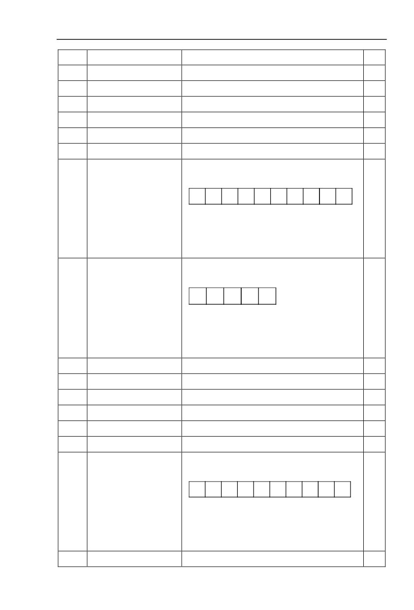
converted to decimal display.
P9.22
Third fault inverter state
Reserved
●
P9.23
Third fault power-on time
The latest fault power-on time
●
P9.24
Third fault running time
The latest fault running time
●
P9.27
Second fault frequency
The latest fault frequency
●
P9.28
Second fault current
The latest fault current
●
P9.29
Second fault bus voltage
The latest fault bus voltage
●
The latest fault digital input terminal status, order as
below :
BIT9
BIT8
BIT7
BIT6
BIT5
BIT4
BIT3
BIT2
BIT1
BIT0
P9.30
Second fault input terminal
DI0
DI9
DI8
DI7
DI6
DI5
DI4
DI3
DI2
DI1
●
When input terminal status is ON, it’s corresponding
binary digit is 1. OFF corresponds to 0. All DI status are
converted to decimal display.
The latest fault digital input terminal status, order as
below :
BIT4
BIT3
BIT2
BIT1
BIT0
P9.31
Second fault output terminal
DO2
DO1
REL2 REL1 FMP
●
When output terminal status is ON, it’s corresponding
binary digit is 1. OFF corresponds to 0. AllDO status
are converted to decimal display.
P9.32
Second fault inverter state
Reserved
●
P9.33
Second fault power-on time
The latest fault power-on time
●
P9.34
Second fault running time
The latest fault running time
●
P9.37
First fault frequency
The latest fault frequency
●
P9.38
First fault current
The latest fault current
●
P9.39
First fault bus voltage
The latest fault bus voltage
●
The latest fault digital input terminal status, order as
below :
BIT9
BIT8
BIT7
BIT6
BIT5
BIT4
BIT3
BIT2
BIT1
BIT0
P9.40
First fault input terminal
DI0
DI9
DI8
DI7
DI6
DI5
DI4
DI3
DI2
DI1
●
When input terminal status is ON, it’s corresponding
binary digit is 1. OFF corresponds to 0. All DI status are
converted to decimal display.
P9.41
First fault output terminal
The latest fault digital input terminal status, order as
●
103
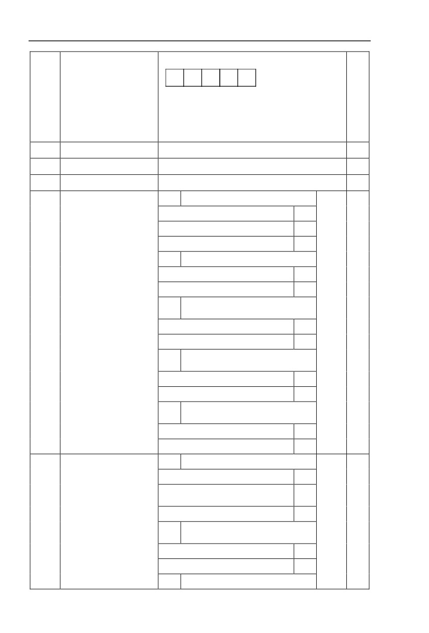
below :
BIT4
BIT3
BIT2
BIT1
BIT0
DO2 DO1 REL2 REL1 FMP
When output terminal status is ON, it’s corresponding
binary digit is 1. OFF corresponds to 0. AllDO status
are converted to decimal display.
P9.42
First fault inverter state
Reserved
●
P9.43
First fault power-on time
The latest fault power-on time
●
P9.44
First fault running time
The latest fault running time
●
1bit
Motor overload(Fault No.11= Err11)
Free stop
0
Stop according to stop mode
1
Keep on running
2
10bit
Input phase lack(Fault No 12=Err12)
Free stop
0
Stop according to stop mode
1
100
Input phase lack(Fault No 13=Err13)
Fault protection action
bit
P9.47
00000
☆
selection 1
Free stop
0
Stop according to stop mode
1
1000
External fault(Fault No.15=Err15)
bit
Free stop
0
Stop according to stop mode
1
10000
Abnormal communication(Fault
bit
No.16=Err16)
Free stop
0
Stop according to stop mode
1
1bit
Encoder fault (Fault No.20=Err20)
Free stop
0
Switch to VF, stop according to stop
1
mode
Fault protection action
Switch to VF, keep on running
2
P9.48
00000
☆
selection 2
Abnormal communication(Fault
10bit
No.21=Err21)
Free stop
0
Stop according to stop mode
1
100bit
Reserved
104
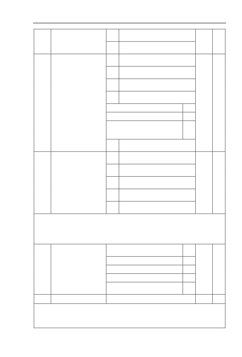
1000
Motor overheating(Fault No.45=
bit
Err45)(Same with P9.47 1 bit)
10000
Runing time arrival(Fault No.26= Err26)
bit
(Same with P9.47 1 bit)
User-defined fault 1(Fault No.27= Err27)
1bit
(Same with P9.47 1 bit)
User-defined fault 2(Fault No.28= Err28)
10bit
(Same with P9.47 1 bit)
Power-on time arrival(Fault No.29= Err29)
100bit
(Same with P9.47 1 bit)
1000
Load off(Fault No.30= Err30)
Fault protection action
bit
P9.49
00000
☆
selection 3
Free stop
0
Stop according to stop mode
1
Decelerate to 7% of motor rated frequency.
Automatically recover to the set frequency if
2
no load off.
10000
PID feedback lost during operation(Fault
bit
No.31= Err31) (Same with P9.47 1 bit)
Excessive speed deviation(Fault No.42=
1bit
Err42) (Same with P9.47 1 bit)
Motor
supervelocity(Fault
No.43=
10bit
Err43)(Same with P9.47 1 bit)
Fault protection action
Initial position fault(Fault No.51= Err51)
P9.50
100bit
00000
☆
selection 4
(Same with P9.47 1 bit)
1000
Reserved
bit
10000
Reserved
bit
If it is set to “free stop”, inverter displays E.****,and stop directly.
If it is set to “stop according to stop mode”, inverter displays A.****, and stop according to the set
stop mode. Inverter displays E.**** after stopped.
If it is set to “keep on running”, inverter displays A.**** and continues running. Running frequency is
set through P9.54.
Operation with the current running
0
frequency
Operation with the set frequency
1
Continued to run when fault
P9.54
Operation with the upper limit frequency
2
0
☆
frequency selection
Operation with the lower limit frequency
3
Operation with the abnormal backup
4
frequency
P9.55
Abnormal backup frequency
60.0%~100.0%
100.0%
☆
When fault occuring during inverter operation , and the fault processing mode set to continuing to
run, inverter would display A** and run with the P9.54 set frequency.
When choosing running frequency as abnormal backup frequency, set value of P9.55 is percentage
of the maximum frequency.
105
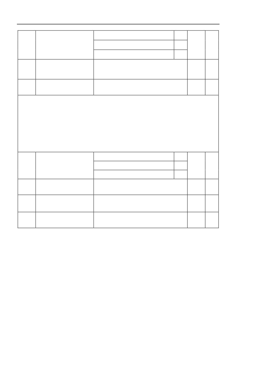
No temperature sensor
0
P9.56
Motor temperature sensor
PT100
1
0
☆
PT1000
2
Motor overheating protection
P9.57
0℃~200℃
110℃
☆
threshold
Motor overheating pre-alarm
P9.58
0℃~200℃
90℃
☆
threshold
Temperature signal of motor temperature sensor should be connected to multi-function I/O expansion
card(optional). Analog input signal AI3 can be used as motor temperature sensor input. Motor temperature
sensor signal is connected to AI3,PGND end.
AI3 analog input end of HV590L supports PT100&PT1000 motor temperature sensors. Correct sensor
type should be set during operation. Motor temperature value is displayed in U0.34.
When motor temperature exceeding the motor overheating protection threshold (P9.57), inverter would
give fault alarm and processing according to the selected protection action mode.
When motor temperature exceeding the motor overheating pre-alarm threshold(P9.58), inverter multi-
function digitalDO would output motor overheating pre-alarm ON signal.
Invalid
0
P9.59
Transient stop selection
Deceleration
1
0
☆
Deceleration to stop
2
Transient stop action pause
P9.60
80.0%~100.0%
90.0%
☆
protection voltage
Transient stop voltage
P9.61
0.00s~100.00s
0.50s
☆
recovery judgment time
Transient stop action
P9.62
60.0%~100.0%(Standard bus voltage)
80.0%
☆
judgment voltage
106
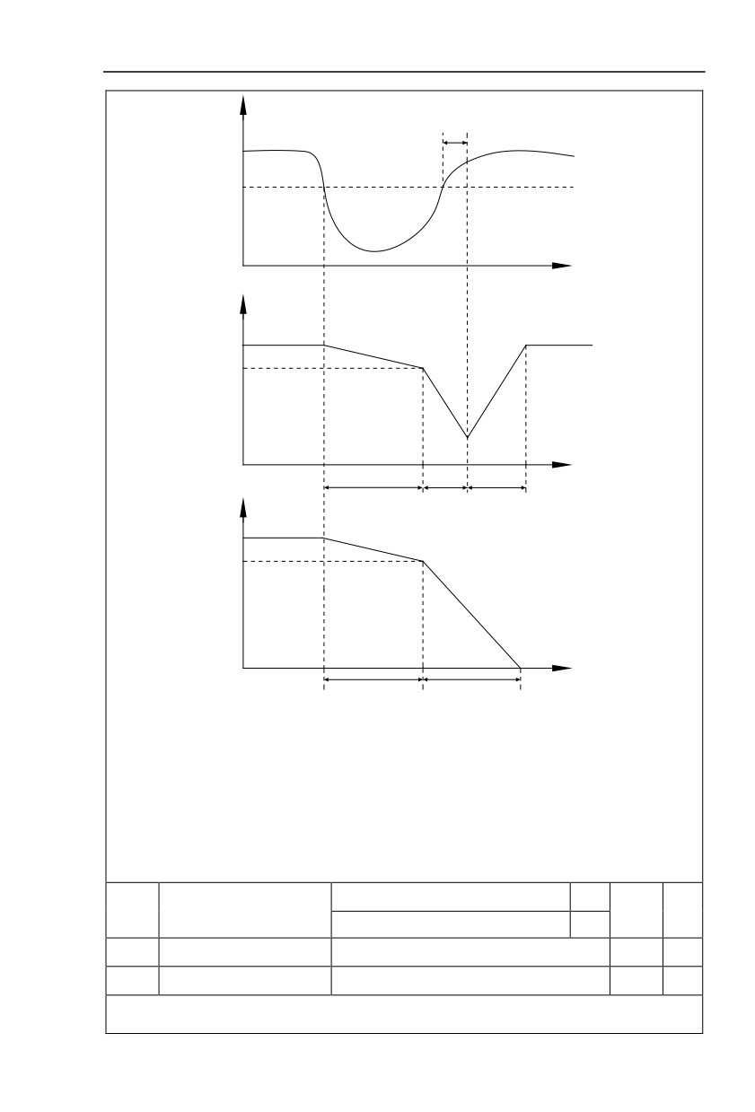
P9.61
Bus voltage
P9.62
t
P9.60
(P9.59=1:Deceleration)
t
Deceleration time3
Recovery acceleration time
Deceleration time4
P9.60
(P9.59=2 : Deceleration to stop)
t
Deceleration time3
Deceleration time4
Fig.5-24 Transient stop action schematic diagram
The function defines when instant outage or voltage suddenly drops, inverter compensating dc bus
voltage decrease by load feedback enery through decreasing output revolving speed, which maintaining
inverter running.
P9.59=1:When instant outage or voltage suddenly drops, inverter decelerates. Inverter normally
accelerates to the set running frequency until bus voltage came to normal. Bus voltage has restored to
normal is based on normal bus voltage duration time. If the time exceeds P9.61 set value , bus voltage is
normal.
P9.59=2:When instant outage or voltage suddenly drops, inverter decelerates to stop.
Invalid
0
P9.63
Load-off protection selection
0
☆
Valid
1
P9.64
Load-off detection level
0.0%~100.0%(Motor rated current)
10.0%
☆
P9.65
Load-off detection time
0.0s~60.0s
1.0s
☆
When the protection function is valid and inverter output current is less than load-off detection level
P9.64(duration time >P9.65), inverter output frequency automatically decreased to 7% of the rated
107
frequency. In the load-off protection period, if the load restored, the inverter automatically restore to the set
running frequency.
P9.67
Over speed detection value
0.0%~50.0%(Maximum frequency)
20.0%
☆
P9.68
Over speed detection time
0.0s~60.0s
1.0s
☆
This function is only valid in speed sensor vector control.
Inverter fault alarm when motor actual revolving speed exceeds the set frequency(excess value >
P9.67 ,duration time >P9.68) .Fault No. 43=Err43.
Excessive speed deviation
P9.69
0.0%~50.0%(Maximum frequency)
20.0%
☆
detection value
Excessive speed deviation
P9.70
0.0s~60.0s
5.0s
☆
detection time
This function is only valid in speed sensor vector control.
Inverter fault alarms when deviation detected between motor actual revolving speed and the set
frequency(deviation>P9.69, duration time>P9.70). Fault No. 42=Err42.
P9.70=0.0s:Excessive speed deviation fault detection is canceled.
5.12 Elevator specifiedfunction group:PL.00-PL.28
For the convenience of customers, we increased the elevator commissioning related
parameters as below:
Description/
Factory
Change
Code
Setting Range
Keyboard Display
Setting
Limit
PL.00
Normal speed(MS command 1)
-100.0%~100.0%
100.0%
☆
PL.01
Leveling speed(MS command 2)
-100.0%~100.0%
11.0%
☆
PL.02
Maintenance speed(MS command 4)
-100.0%~100.0%
40.0%
☆
PL.00 is the Normal speed of the elevater. PL.01 is the Creep speed of the elevater.PL.02 is the
inspection speed of the elevater.
PL.03
Drive run delay On set time
0.00~10.00s
0.20s
☆
This parameter define the delay time between the run command and the drive actually output.
PL.04
Mc contactor delay Off set time
0.00~10.00s
0.20s
☆
The MC contactor de-energise after the desire set time has elapse. This parameter define the delay
time.
If MC is controlled by elevator controller, then PL.03and PL.04 are useless
PL.05
Brake release current threshold
0~200
5.0%
☆
PL.06
Brake release frequency threshold
0~25.0Hz
0.0Hz
☆
PL.07
Brake release delay On set time
0.00~5.00s
0.0s
☆
If the drive output frequency is exceed the frequency threshold defined by PL.06, and output current is
exceed the currentthreshold defined by PL.05, delay the time defined by PL.05, the brake is released.
PL.08
Brake apply frequency threshold
0~25.0Hz
0.5Hz
☆
108
PL.09
Brake apply delay OFF set time
0.00~5.00s
0.2s
☆
When the drive is stopping, if the output frequency is below thefrequency threshold defined by PL.08, delay
the time defined by PL.09, the brake is applied.
PL.10
Startup frequency
0.00Hz~10.00Hz
1Hz
☆
PL.11
Startup frequency active set time
0.0s~100.0s
0.3s
☆
To ensure the torque at the time of startup, proper startup frequency shall be set. In addition, in order
to set up magnetic flux when waiting for the startup of the motor, the startup frequency shall remain for a
certain period of time before accelerating to the setup frequency.
Start frequency PL.10 is not affected by the lower frequency limit.If the frequency reference value
(frequency source) is lower than the startup frequency, the inverter cannot start and will be in standby
status.
In positive&negative switching process, startup frequency retention time Yes not work.Startup
frequency retention time is not included in the acceleration time,but included in the simple PLC running
time.
Example 1:
P0.03=0 means the frequency source is digital reference.
P0.08=2.00Hz means the digital setup frequency is 2.00Hz.
PL.10=5.00Hz means the startup frequency is 5.00Hz.
PL.11=2.0s means that the startup frequency retention time is 2.0s.
In this case, the inverter will be in the standby status and its output frequency is 0Hz.
Example 2:
P0.03=0 means the frequency source is digital reference.
P0.08=10.00Hz means the digital setup frequency is 10.00Hz.
PL.10=5.00Hz means the startup frequency is 5.00Hz.
PL.11=2.0s means that the startup frequency retention time is 2.0s.
In this case, the inverter accelerates to 5.00 Hz and remains for 2 seconds, and then accelerates to
the setup frequency 10Hz.
PL.12
Acceleration time 1
0.00s~65000s
3.0s
☆
PL.13
Deceleration time1
0.00s~65000s
2.0s
☆
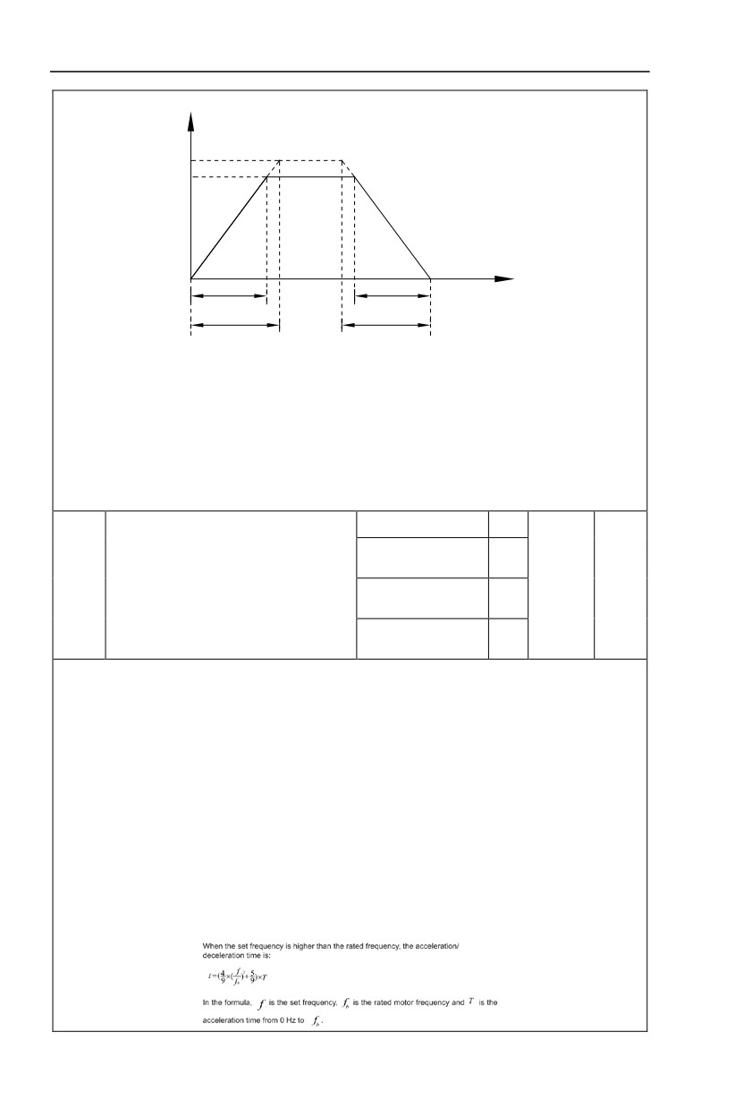
The acceleration time means the time t1 needed for the inverter to accelerate from 0Hz to the
reference frequency(P0.25).
The deceleration time means the time t2 needed for the inverter to decelerate from the reference
frequency (P0.25) to 0Hz.
The descriptionof acceleration and deceleration time are as shown in Figure below:
109
Output frequency
Hz
Acceleraion/deceleration
reference frequency
Setting frequency
t
Actual acceleration time
Actual deceleration time
Setting acceleration time
t1
t2
Setting deceleration time
Acceleration/decelerationtime schematic diagram
HV590L totally offers 4 groups of speed-up/speed-DOWN time for selection,you can shift through
digital input terminal DI,4 groups of them are shown as follows:
GROUP 1:PL.12、PL.13;
GROUP 2:P8.03、P8.04;
GROUP 3:P8.05、P8.06;
GROUP 4:P8.07、P8.08.
Straight acc. /dec.
0
S curve acc. /dec.
☆
1
mode A
PL.14
Acceleration/deceleration mode
3
S curve acc. /dec.
2
mode B
☆
S curve acc. /dec.
3
mode C
It is used to select the frequency change mode during the inverter start and stop process.
0: Straight acceleration/ deceleration
The output frequency increases or decreases along the straight line. HV590L series inverter provides 4
types of acceleration/deceleration time.It can select acceleration/ deceleration time via the multifunctional
digital input terminals.
1:S-curve acceleration/ deceleration mode A
The output frequency increases or decreases along the straight line. S curve is generally used in the
applications where start and stop processes are relatively gentle, such as elevator and conveyor belt.The
acceleration/ deceleration time is consistent with the straight acceleration/ deceleration time.Function
codes of PL.15 and PL.16 can be respectively definedthe time proportion of starting-segment and finishing-
segment for S-curve acceleration/ deceleration.
2: S-curve acceleration/deceleration B
In this curve, the rated motor frequency is always the inflexion point. This mode isusually used in
applications where acceleration/deceleration is required at the speedhigher than the rated frequency.
110
3: S-curve acceleration/deceleration C:
In this curve, the elevator can worked in a best performance during acceleration/deceleration, it’s
special for elevator applicatios and the curve is made according to rich experience and a large number of
trials, it’s been proved in actual working conditions.
PL.15
Time proportion of S-Ramp at acc Start
0.0% to Min[(100%- PL-16)]
80.0%
☆
PL.16
Time proportion of S-Ramp at acc end
0.0% to Min[(100%- PL-15)]
10.0%
☆
Function code of PL.15 and PL.16 can be respectively defined the time proportion between the S-
curve initial-segment and finishing-segment for S-curve acceleration/ deceleration A. They are required to
meet the standard of PL.15+ PL.16≤100.0%.
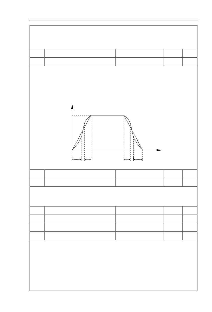
t1 in the Figure below is the parameters defined by PL.15, in this period of time which the changing
slope of output frequency is becoming larger and larger. t2 is defined by parameter PL.16, in this period of
time which the changing slope of output frequency change to zero. The changing slope of output frequency
is fixing within the time of t1 and t2.
Output frequency Hz
Setting frequency f
t
t1
t2
t1
t2
S-curve acceleration/deceleration schematicdiagram A
PL.17
Time proportion of S-Ramp at decel Start
0.0% to Min[(100%- PL-18)]
20.0%
☆
PL.18
Time proportion of S-Ramp at decel end
0.0% to Min[(100%-PL-17)]
30.0%
☆
PL.17 and PL.18 have similar function as PL.15 and PL.16, the different is they’re for decal Start and End.
S curve acc. /dec. mode C is the elevator specialized Acceleration/deceleration mode. It is shown as figure
following.
PL.19
DC injection 2 frequency threshold
0.0Hz~maximum frequency
0.5Hz
☆
PL.20
DC injection 2 delay on set time
0.0s~36.0s
0.0s
☆
PL.21
DC injection 2 level
0%~100%
30.0%
☆
PL.22
DC injection 2 active set time
0.0s~100.0s
0.5s
☆
DC brake initial frequency at stop: During the process of decelerating to stop, when the running
frequency at stop reaches this frequency, it will start the process of DC brake.
DC brake waiting time at stop: Prior to the beginning of DC brake at stop, the inverter will terminate
the output, and then start DC brake after this delay time. It is used to prevent over current fault due to DC
brake which starts at the time of higher velocity.
DC brake current at stop: The DC brake quantity added shall be set according to the percentage
setting of the rated current of the inverter. The higher the brake current is, more powerful the brake effect is.
DC brake time at stop: It refers to the continuous DC brake time. If this DC brake time is set to 0, it
111
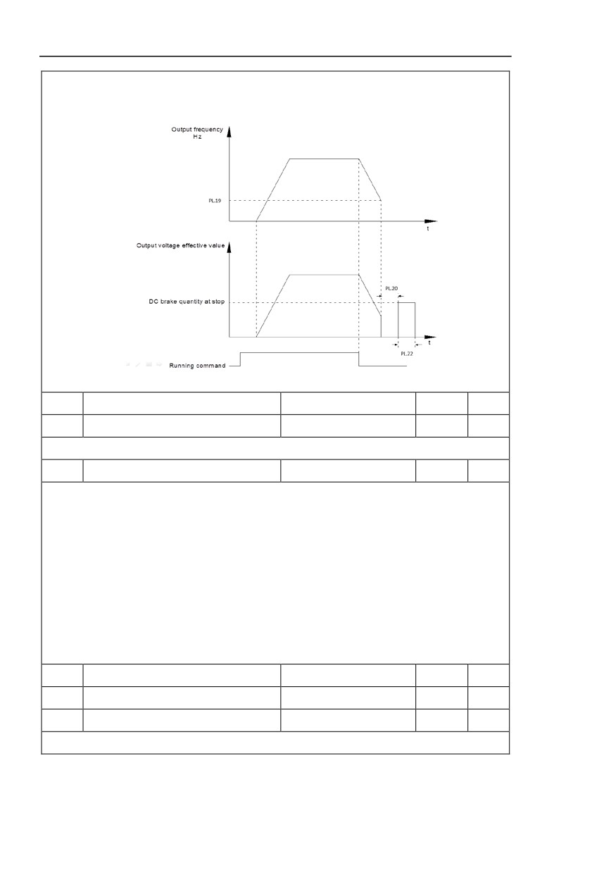
indicates that there is no DC brake process, and the inverter will stop according to the setting process of
decelerating to stop.
The process of DC brake at stop is as shown in Figure below.
DC brake schematicdiagram
PL.23
Time proportion of S-Ramp at stop Start
0.0% to Min[(100%- PL-24)]
20.0
☆
PL.24
Time proportion of S-Ramp at stop end
0.0% to Min[(100%- PL-23)]
30.0
☆
PL.23, PL.24 is for the stop decelerationS mode.
PL.25
Motor overload time adjust
0.01-10.00
1.00
☆
Parameter PL.25 to change the protection time. When the value of PL.25 is 1.00, it is standard
protection time. Increase the value of PL.25, the protection time is shorter.
The protection time of motor is as following:
115% rating motor current
1 hour 20 minutes
125% rating motor current
40 minutes
135% rating motor current
15 minutes
145% rating motor current
5 minutes
155% rating motor current
2 minutes
165% rating motor current
2 minutes
175% rating motor current
2 minutes
PL.26
VF control slip Coef for generation
0.0-200.0
0
☆
PL.27
VC control slip Coef for generation
0-100
100
☆
PL.28
Stop Deceleration time1
0.00s~65000s
2.0
☆
PL.28 is the time from you get the stop command to 0Hz. ( from disable UP or DOWN to 0Hz)
112
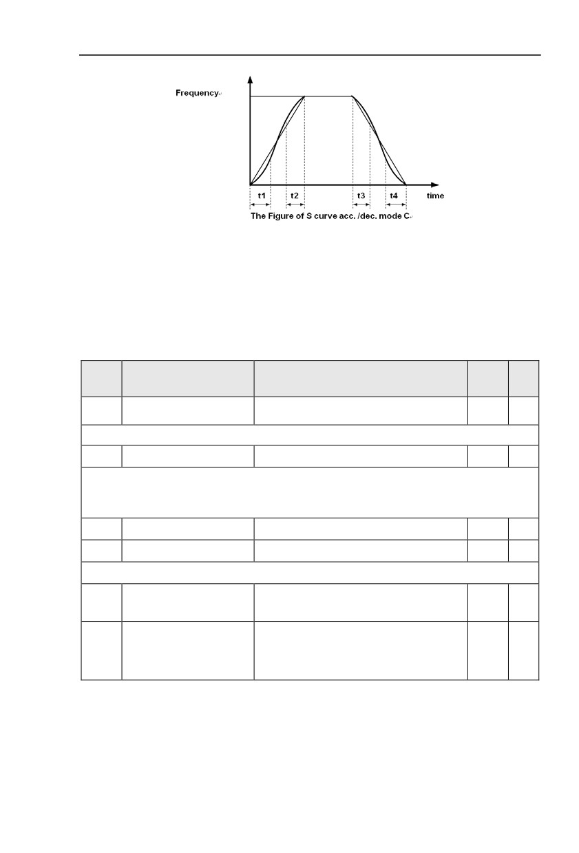
In this figure, t1 is defined by the parameter PL.15, t2 is defined by the parameter PL.16, t3 is defined
by the parameter PL.17, t4 is defined by the parameter PL.18,
5.13 UPS function:Pb.00-Pb.05
This Group defines the parameters of UPS function.
Description/
FactoryChange
Code
Setting Range
Keyboard Display
Setting
Limit
UPS referencefrequency
Pb.00
0.0%~100.0%
10.0
☆
The freqency of UPS mode.
Pb.01
UPS current threshold
0-200
100%
☆
When the elevator is in UPS mode, the drive will be autoresearch light load direction to protect passengers can be
reach levelling floor for safety. If the motor current is less than the UPS current threshold, the current direction is
the light load direction. Otherwise the inverse direction is the light load direction.
Pb.02
UPS Acceleration time
0.00s~65000s
3.0
☆
Pb.03
UPS Deceleration time
0.00s~65000s
3.0
☆
Pb.02, Pb.03 define the acceleration time and deceleration time at UPS mode
0:three phase 380v/415v
Pb.04
UPS phase mode
0
☆
1:single phase 200v/240v
60.0-140.0
UPS single/two phase
When use single phase UPS, under voltage
Pb.05
60.0
☆
undervoltage poiont
point is active by Pb.05. Otherwise under
voltage point is active by A5.06.
113
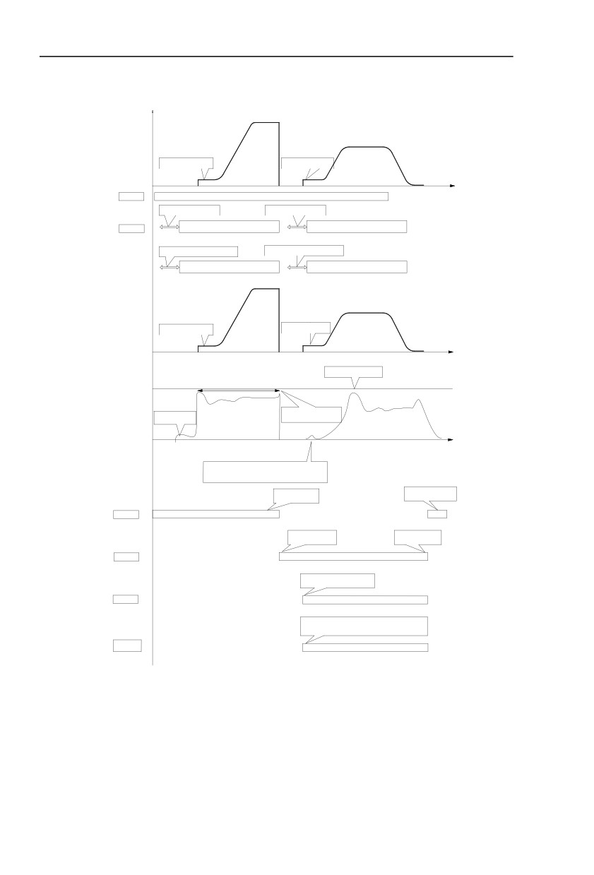
CASE 1 UPS mode Light load search operation for output current of < 100%
Frequency
Reference
50Hz
5Hz
Brake Release Frequency
Brake Release Frequency
Threshold PL.06=0.00Hz
Threshold PL.06=0.00Hz
Time
0
DI1
Forward RunON
OFF
MC reaction time*
MC reaction time*
dependant on the contactor
dependant on the contactor
DI6 IGBT EnableON
OFF
Drive Run Permit Delay ON Set-Time
Drive Run Permit Delay ON Set-Time
PL.03=0.20Sec
PL.03=0.20Sec
IGBT's active ON
OFF
Actual Running
Frequency
50Hz
5Hz
Brake Release Frequency
Brake Release Frequency
Threshold PL.06=0.00Hz
Threshold PL.06=0.00Hz
0
Current threshold in UPS
mode Pb.01
Current
threshold
Pb.01
UPS judge current will be
Brake Release Current
continuing remember
Threshold PL.05=5%
delay 2 seconds at start
Actual Output
OA
Current
Remembered current(U0-12)is higher than UPS threshold
curent(Pb.01);it is the heavy load direction before UPS
power on,so it will be reverse the run direction
AC Power off before
AC Power on during UPS
UPS Power on
Power off
AC Power
ON
OFF
UPS Power on after AC
UPS Power off during
Power off
AC Power on
UPS Power
ON
OFF
UPS Enable signal need be active
when UPS power on
DI7 UPS Enable
ON
OFF
Single phase UPS need be active this signal,it will be
remove input phase loss protection(Pb.04 set 1 or
F4-07 set 52 and be active )
DI8
Single phase
ON
UPS Enable
OFF
Ups Light load direction: UPS mode will be auto research light load direction, and it will be running to nearest light load
direction floor. Which is decided by Pb-01 and U0-12, if U0-12 is lower than Pb-01, it will be continue to keep the run
direction before UPS; otherwise it will be reverse the direction.
For some applications, the status of Single phase UPS Enable needs to be checked before inverter
starts up according to DI8 or F8-68, because it will be removed input phase loss
protection in UPS mode, otherwise it will be trip Err12.
114
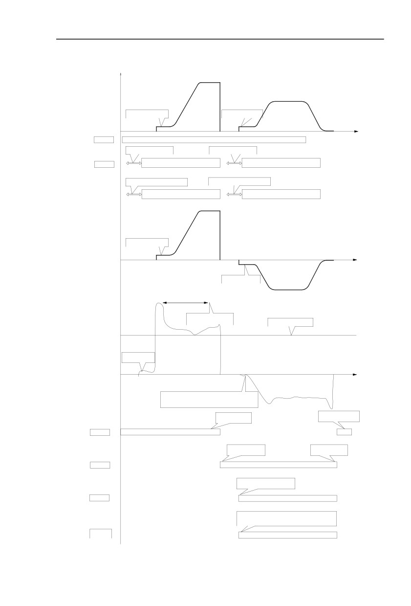
CASE 2 UPS mode Light load search operation for output current of > 100%
Frequency
Reference
50Hz
5Hz
Brake Release Frequency
Brake Release Frequency
Threshold PL.06=0.00Hz
Threshold PL.06=0.00Hz
Time
0
DI1
Forward RunON
OFF
MC reaction time*
MC reaction time*
dependant on the contactor
dependant on the contactor
DI6 IGBT EnableON
OFF
Drive Run Permit Delay ON Set-Time
Drive Run Permit Delay ON Set-Time
PL.03=0.20Sec
PL.03=0.20Sec
IGBT's active
ON
OFF
Actual Running
Frequency
50Hz
5Hz
Brake Release Frequency
Threshold PL.06=0.00Hz
0
Brake Release Frequency
Threshold PL.06=0.00Hz
UPS judge current will be
continuing remember
Current threshold in UPS
delay 2 seconds at start
mode Pb.01
Current
threshold
Pb.01
Brake Release Current
Threshold PL.05=5%
Actual Output
OA
Current
Remembered current(U0-12)is higher than UPS threshold
curent(Pb.01);it is the heavy load direction before UPS
power on,so it will be reverse the run direction
AC Power off before
AC Power on during UPS
UPS Power on
Power off
AC Power
ON
OFF
UPS Power on after AC
UPS Power off during
Power off
AC Power on
UPS Power
ON
OFF
UPS Enable signal need be active
when UPS power on
DI7 UPS Enable
ON
OFF
Single phase UPS need be active this signal,it will be
remove input phase loss protection(Pb.04 set 1 or
F4-07 set 52 and be active )
DI8
Single phase
ON
UPS Enable
OFF
115
5.14 MS speed function&simple PLC function:PC.00-PC.51
MS speed command of HV590L has more abundant function than the usual MS speed
function. It could not only realize MS speed function, but also can be used as VF saparation
voltage source and PID reference source.Therefore, dimension of MS speed command is a
relative value.
Simple PLC function is different from HV590L user programmable function. Simple PLC can
only achieve simple combination of MS speed command, while user programmable function has
more abundant and practical uses. For specifications please refer to A7 group.
Description/
Factory
Change
Code
Setting Range
Keyboard Display
Setting
Limit
PC.00
MS command 0
-100.0%~100.0%
10.0%
☆
PC.01
Reserved
------
--
☆
PC.02
Reserved
------
--
☆
PC.03
MS command 3
-100.0%~100.0%
12.0%
☆
PC.04
Reserved
------
--
☆
PC.05
MS command 5
-100.0%~100.0%
13.0%
☆
PC.06
MS command 6
-100.0%~100.0%
14.0%
☆
PC.07
MS command 7
-100.0%~100.0%
15.0%
☆
☆
PC.08
MS command 8
-100.0%~100.0%
0.0%
PC.09
MS command 9
-100.0%~100.0%
0.0%
☆
PC.10
MS command 10
-100.0%~100.0%
0.0%
☆
☆
PC.11
MS command11
-100.0%~100.0%
0.0%
☆
PC.12
MS command 12
-100.0%~100.0%
0.0%
PC.13
MS command 13
-100.0%~100.0%
0.0%
☆
PC.14
MS command 14
-100.0%~100.0%
0.0%
☆
☆
PC.15
MS command 15
-100.0%~100.0%
0.0%
MS speed command can be used on three occasions:frequency source, VF saparation voltage
source, process PID set source.
Dimension of MS speed command is a relative value ranging from -100.0% to 100.0%. When used as
command source, it’s the percentage of maximum frequency. When used as VF saparation voltage source,
it’s the percentage of motor rated voltage. When used as PID set source, dimension conversion is not
needed during the process.
MS command should be selected according to the different states of multi-function digit DI terminals.
For details please refer to P4 group.
Single running stop
0
PC.16
PLC running mode
Single running end remaining final value
1
0
☆
Continuous circulation
2
Simple PLC command can be used on two occasions:frequency source, VF saparation voltage source.
116
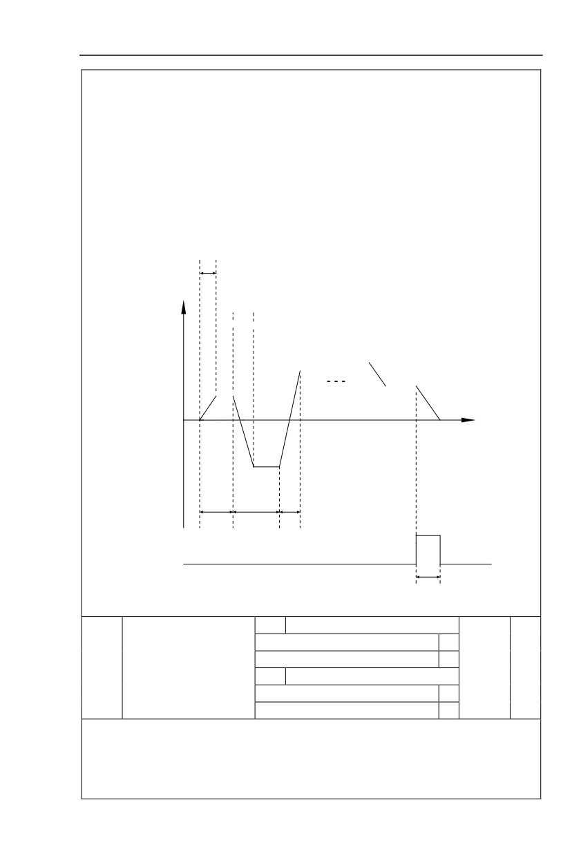
Fig 5-30 is the schematic diagram of simple PLC that used as frequency source. Positive & negative of
PC.00~PC.15 determines the running direction.
PLC has 3 running modes as frequency source(VF saparation voltage source is not provided with the
3 modes):
0: Single running stop
Upon completion of one single cycle of the inverter, it will stop automatically and will not start until
running command is given again.
1:Single running end remaining final value
Upon completion of one single cycle of the inverter, the inverter will remain the running frequency and
direction of last one phase. After the inverter restarted upon stop, it will run from the initial status of PLC.
2: Continuous circulation
Upon completion of one single cycle of the inverter, it will enter next cycle and not stop until stop
command is given.
PC.19
Running direction
PC.21
PC.14
PC.02
PC.15
PC.00
t
PC.01
PC.18
PC.20
PC.23
DO or RELAY output
250ms pulse
Fig.5-30Simple PLC schematic diagram
1bit
Power off memory selection
Power off without memory
0
PLC power off memory
Power off with memory
1
PC.17
00
☆
selection
10bit
Stop memory selection
Stop without memory
0
Stop with memory
1
PLC power off memory refers to memorizing the PLC running stage and running frequency before
power off, and continues to run from the memory stage upon next power-on. If 1bit is set to 0, PLC process
would restart upon power-on.
PLC stop memory refers to the record of PLC running stage and running frequency of the time before.
Next time PLC continues to run from the memory stage. If 10bit is set to 0, PLC process would restart upon
117
power-on.
PC.18
PLC 0segment running time
0.0s(h) ~ 6553.5s(h)
0.0s(h)
☆
PC.19
PLC 0segment acc./dec. time
0~3
0
☆
☆
PC.20
PLC 1segment running time
0.0s(h)~6553.5s(h)
0.0s(h)
PC.21
PLC 1segment acc./dec. time
0~3
0
☆
PC.22
PLC 2segment running time
0.0s(h)~6553.5s(h)
0.0s(h)
☆
☆
PC.23
PLC 2segment acc./dec. time
0~3
0
PC.24
PLC 3segment running time
0.0s(h)~6553.5s(h)
0.0s(h)
☆
PC.25
PLC 3segment acc./dec. time
0~3
0
☆
☆
PC.26
PLC 4segment running time
0.0s(h)~6553.5s(h)
0.0s(h)
☆
PC.27
PLC 4segment acc./dec. time
0~3
0
PC.28
PLC 5 segment running time
0.0s(h)~6553.5s(h)
0.0s(h)
☆
PC.29
PLC 5segment acc./dec. time
0~3
0
☆
☆
PC.30
PLC 6segment running time
0.0s(h)~6553.5s(h)
0.0s(h)
PC.31
PLC 6segment acc./dec. time
0~3
0
☆
PC.32
PLC 7segment running time
0.0s(h)~6553.5s(h)
0.0s(h)
☆
☆
PC.33
PLC 7segment acc./dec. time
0~3
0
PC.34
PLC 8segment running time
0.0s(h)~6553.5s(h)
0.0s(h)
☆
PC.35
PLC 8segment acc./dec. time
0~3
0
☆
☆
PC.36
PLC 9segment running time
0.0s(h)~6553.5s(h)
0.0s(h)
☆
PC.37
PLC 9segment acc./dec. time
0~3
0
PC.38
PLC 10segment running time
0.0s(h)~6553.5s(h)
0.0s(h)
☆
PC.39
PLC 10segment acc./dec.time
0~3
0
☆
☆
PC.40
PLC 11segment running time
0.0s(h)~6553.5s(h)
0.0s(h)
PC.41
PLC 11segment acc./dec. time
0~3
0
☆
PC.42
PLC 12segment running time
0.0s(h)~6553.5s(h)
0.0s(h)
☆
☆
PC.43
PLC 12segment acc./dec. time
0~3
0
PC.44
PLC 13segment running time
0.0s(h)~6553.5s(h)
0.0s(h)
☆
PC.45
PLC 13segment acc./dec. time
0~3
0
☆
☆
PC.46
PLC 14segment running time
0.0s(h)~6553.5s(h)
0.0s(h)
☆
PC.47
PLC 14segment acc./dec. time
0~3
0
PC.48
PLC 15segment running time
0.0s(h)~6553.5s(h)
0.0s(h)
☆
PC.49
PLC 15segment acc./dec. time
0~3
0
☆
118
S(second)
0
PC.50
Running time unit
0
☆
H(hour)
1
Function code PC.00 reference
0
AI1
1
AI2
2
MS command 0 reference
AI3(Potentiometer)
3
PC.51
0
☆
mode
PULSE
4
PID
5
Preset frequency(P0.08) reference,
6
UP/DOWN can be modified
It is used to select the reference channel of MS speed 0.
Besides choosing PC.00, MS command 0 has many other options, which is convenient for switching
between MS command and other set modes.
Both MS command and simple PLC used as frequency source can easily realize switching between
the two frequency sources.
5.15 Communication function group:Pd.00-Pd.06
Please refer to《HV590Lcommunication protocol》
Description/
FactoryChange
Code
Setting Range
Keyboard Display
Setting
Limit
1bit
MODBUS
300BPS
0
600BPS
1
1200BPS
2
2400BPS
3
4800BPS
4
9600BPS
5
19200BPS
6
Pd.00
Baud rate
38400BPS
7
5005
☆
57600BPS
8
115200BPS
9
10bit
Profibus-DP
115200BPS
0
208300BPS
1
256000BPS
2
512000BPS
3
100
Reserved
119
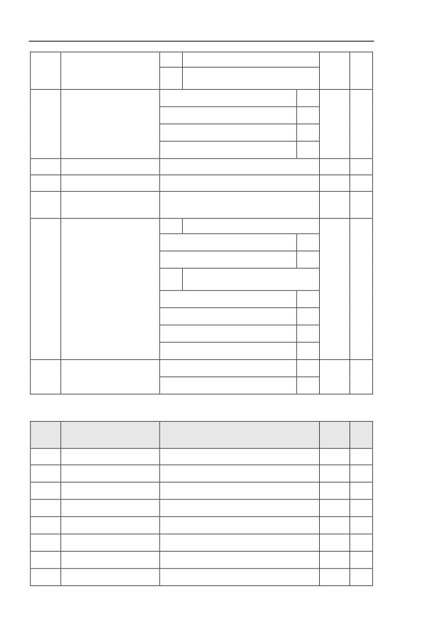
bit
1000
Reserved
bit
Without calibration (8-N-2)
0
Even parity calibration(8-E-1)
1
Pd.01
Data format
0
☆
Uneven parity calibration(8-O-1)
2
8-N-1
3
Pd.02
Local address
1-247, 0 is broadcast address
1
☆
Pd.03
Response delay
0ms-20ms
2
☆
Excessive communication
Pd.04
0.0(invalid), 0.1s-60.0s
0.0
☆
time
1bit
MODBUS
Non-standard MODBUS protocal
0
Standard MODBUS protocal
1
10
Profibus-DP
bit
Pd.05
Data transformat selection
31
☆
PPO1 format
0
PPO2 format
1
PPO3 format
2
PPO5 format
3
0.01A
0
Communication read
Pd.06
0
☆
current resolution
0.1A
1
5.16 User customization function code:PE.00-PE.29
Description/
FactoryChange
Code
Setting Range
Keyboard Display
Setting
Limit
PE.00
User function code 0
P0.00~PP.xx,A0.00~Ax.xx,U0.xx
P0.00
☆
PE.01
User function code 1
P0.00~PP.xx,A0.00~Ax.xx,U0.xx
P0.00
☆
PE.02
User function code 2
P0.00~PP.xx,A0.00~Ax.xx,U0.xx
P0.00
☆
PE.03
User function code 3
P0.00~PP.xx,A0.00~Ax.xx,U0.xx
P0.00
☆
PE.04
User function code 4
P0.00~PP.xx,A0.00~Ax.xx,U0.xx
P0.00
☆
PE.05
User function code 5
P0.00~PP.xx,A0.00~Ax.xx,U0.xx
P0.00
☆
PE.06
User function code 6
P0.00~PP.xx,A0.00~Ax.xx,U0.xx
P0.00
☆
PE.07
User function code 7
P0.00~PP.xx,A0.00~Ax.xx,U0.xx
P0.00
☆
120
PE.08
User function code 8
P0.00~PP.xx,A0.00~Ax.xx,U0.xx
P0.00
☆
PE.09
User function code 9
P0.00~PP.xx,A0.00~Ax.xx,U0.xx
P0.00
☆
PE.10
User function code 10
P0.00~PP.xx,A0.00~Ax.xx,U0.xx
P0.00
☆
PE.11
User function code 11
P0.00~PP.xx,A0.00~Ax.xx,U0.xx
P0.00
☆
PE.12
User function code 12
P0.00~PP.xx,A0.00~Ax.xx,U0.xx
P0.00
☆
PE.13
User function code 13
P0.00~PP.xx,A0.00~Ax.xx,U0.xx
P0.00
☆
PE.14
User function code 14
P0.00~PP.xx,A0.00~Ax.xx,U0.xx
P0.00
☆
PE.15
User function code 15
P0.00~PP.xx,A0.00~Ax.xx,U0.xx
P0.00
☆
PE.16
User function code 16
P0.00~PP.xx,A0.00~Ax.xx,U0.xx
P0.00
☆
PE.17
User function code 17
P0.00~PP.xx,A0.00~Ax.xx,U0.xx
P0.00
☆
PE.18
User function code 18
P0.00~PP.xx,A0.00~Ax.xx,U0.xx
P0.00
☆
PE.19
User function code 19
P0.00~PP.xx,A0.00~Ax.xx,U0.xx
P0.00
☆
PE.20
User function code 20
P0.00~PP.xx,A0.00~Ax.xx,U0.xx
P0.00
☆
PE.21
User function code 21
P0.00~PP.xx,A0.00~Ax.xx,U0.xx
P0.00
☆
PE.22
User function code 22
P0.00~PP.xx,A0.00~Ax.xx,U0.xx
P0.00
☆
PE.23
User function code 23
P0.00~PP.xx,A0.00~Ax.xx,U0.xx
P0.00
☆
PE.24
User function code 24
P0.00~PP.xx,A0.00~Ax.xx,U0.xx
P0.00
☆
PE.25
User function code 25
P0.00~PP.xx,A0.00~Ax.xx,U0.xx
P0.00
☆
PE.26
User function code 26
P0.00~PP.xx,A0.00~Ax.xx,U0.xx
P0.00
☆
PE.27
User function code 27
P0.00~PP.xx,A0.00~Ax.xx,U0.xx
P0.00
☆
PE.28
User function code 28
P0.00~PP.xx,A0.00~Ax.xx,U0.xx
P0.00
☆
PE.29
User function code 29
P0.00~PP.xx,A0.00~Ax.xx,U0.xx
P0.00
☆
This function group is the user customization function code.
Users can put the required parameters (among all HV590L function codes) to the PE group as the
user customization function group.
PE group can offer 30 user customization function codes at most.When PE displays P0.00, it means
user function code is null.
In user customization function mode, display of the function codes is defined through PE.00~PE.31.
Sequence is consistent with the PE function codes, skip P0.00.
5.17 Function code management:PP.00-PP.04
Description/
FactoryChange
Code
Setting Range
Keyboard Display
Setting
Limit
PP.00
User password
0~65535
0
☆
121
The password set function is used to prohibit the unauthorized person from viewing and modifying
the parameters.
When the parameter is set to any non-zero number, the password protection function is enabled. If
no password is needed, change the parameter value to 00000.
After the user password is set and takes effect, when entering the password setting state, if the
user password is incorrect, you cannot view and modify the parameter. You can only view the operation
display parameters and stop displaying parameters.
Please keep your password in mind. If you set the password mistakenly orforget the password,
please contact the manufacturer.
No function
0
Restore to factory default value,motor
1
parameter not included
Clear memory
2
PP.01
Parameter initialization
0
★
Restore factory parameters, Including
3
motor parameters
Backup user current parameter
4
Restore user backup parameter
501
0: No function.
1:Restore to factory default value,motor parameter not included
The inverter restores all the parameters excluding the following parameters of the factory default
values:
Motor parameters, P0.22, fault record information, P7.09, P7.13, P7.14.
2:Clear memory
The inverter clears the fault records , P7.09, P7.13 and P7.14 to zero.
3:Restore factory parameters, Including motor parameters
PP.01=3,The inverter restores all the parameters excluding the following parameters of the factory
default values
4:Backup user current parameter
It is the backup of user current setting parameters, which is convenient for the user to restore the
disordered parameters .
501:Restore user backup parameter
It is used to restore the backup of user parameters, that is, restore the backup parameters whichis
set through PP.01=501.
1bit
U group display selection
No display
0
Display
1
PP.02
Parameter display attribute
11
★
10bit
A group display selection
No display
0
Display
1
Personalized parameter
1bit
Custom parameter display selection
PP.03
00
☆
display selection
No display
0
122
Display
1
10bit
User change parameter display selection
No display
0
Display
1
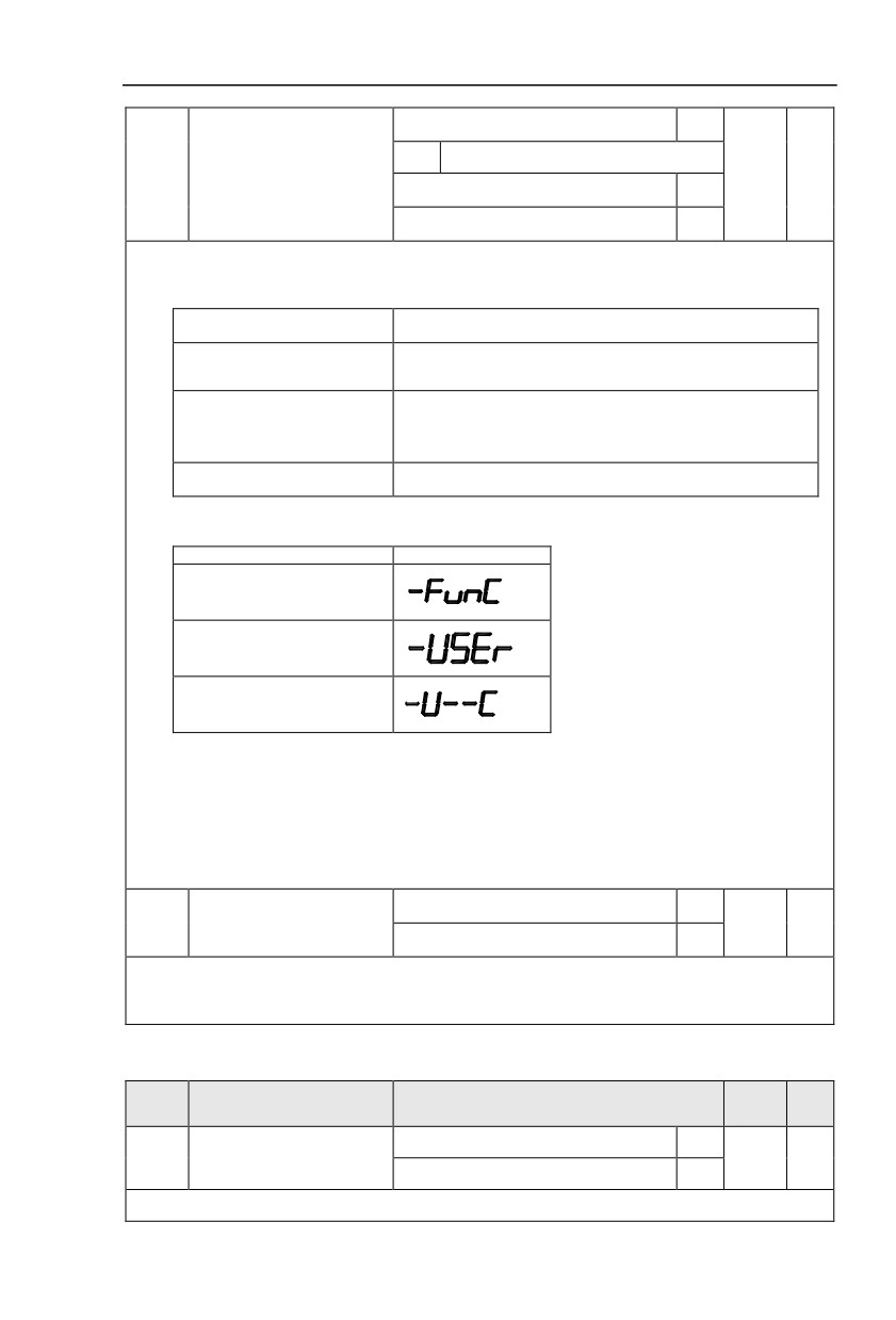
The establishment of parameter display selectionis basically convenient for the users viewing the
different arrangement forms of function parameters according to the actual needs. Three display
methods are offered as below:
Name
Discription
Sequence display inverter function parameters, respectively
Function parameter mode
P0~PF、A0~AF、U0~UF.
User customization display of specified function
User customization parameter
parameters(32 at most). The display parameters is
mode
determined through PE group.
User change parameter mode
Parameters which are different from factory default.
When existing display for PP.03, user could switch into different display mode through QUICK key.
Function parameter display mode as default.
Parameter display mode
Display
Function parameter mode-
FunC
User customization parameter
mode-USEt
User change parameter
mode-U--C
Display codes as below:
HV590L series offers two groups of personalized parameter display mode:user customization
function mode, user change parameter mode.
In user customization parameter mode, sign u is added to the user customization function code as
default.
In user change parameter mode, sign c is added to the user customization function code as
default. E.g:P1.00 is displayed as cP1.00 .
Can be modified
0
Function codes modification
PP.04
0
☆
attribute
Can not be modified
1
This function is used to prevent misoperation of the function parameters.
PP.04=0:All the function codes can be modified.
PP.04=1:All the function codes can only be viewed, but not modified.
5.18 Torque control group: A0.00-A0.08
Description/
FactoryChange
Code
Setting Range
Keyboard Display
Setting
Limit
Speed control
0
Speed/ torque control mode
A0.00
0
★
selection
Torque control
1
A0.00 is used to select inverter control mode:speed control or torque control.
123
Multi-function digit DI terminal of HV590L is equipped with two functions relating torque control:
Torque control banned(Function29), speed control/torque control switching (function 46). The two terminals
should be matched with A0.00 to realize switching between speed control and torque control.
A0.00 set the control mode when speed/torque control switching terminal invalid. If the speed/torque
control switching terminal is valid, control mode is equivalent to the inversion of A0.00 value.
When function 29 is valid, speed control mode is fixed for the inverter .
Digital setup(A0.03)
0
AI1
1
AI2
2
AI3(Potentiometer)
3
Torque setup source selection
A0.01
0
★
in torque control mode
PULSE
4
Commuication setup
5
MIN(AI1,AI2)
6
MAX(AI1,AI2)
7
Torque digital setup in torque
A0.03
-200.0%~200.0%
150%
☆
control mode
A0.01 is used to select torque set source. There are totally 8 kinds of torque set mode.
Torque set is a relative value, which 100% corresponding to inverter rated torque. Set range:
200.0%~200.0%.Maximum torque is 2 times that of inverter rated torque
When the torque is set by selection 1~7, 100% of communication ,analog input, pulse input
corresponding to A0.03.
Torque control forward
A0.05
0.00Hz~Maximum frequency(P0.10)
50.00Hz
☆
maximum frequency
Torque control reverse
A0.06
0.00Hz~Maximum frequency(P0.10)
50.00Hz
☆
maximum frequency
A0.05, A0.06 are used to set forward or reverse maximum running frequency in torque control mode.
In inverter toque control mode, if load torque is less than motor output toque, the motor revolving
speed would speed up. In case of galloping or other accidents of mechanical system , motor maximum
revolving speed must be limited.
A0.07
Torque control acc. time
0.00s~65000s
0.00s
☆
A0.08
Torque control dec. time
0.00s~65000s
0.00s
☆
In torque control mode , rate of speed change of motor and load is decided by the difference
between motor output toque and load torque. Therefore, motor speed may change fast, causing noise
or excessive mechanical stress problems. By setting the torque control acc./dec. time, can make the
motor speed changes smoothly.
A0.07 and A0.08 should be set to 0.00s in situations where torque rapid response is needed.
E.g:Two motors drive the same load, to make sure of load uniform distribution , one is set as host
inverter(speed control mode) and another is the slave one(torque control mode). Actual output torque of
the host inverter is the torque command of the slave, and slave torque is required to quickly follow the
host torque, then torque control acc./dec. time is set to 0.00s for the slave inverter.
5.19 VirtualIO: A1.00-A1.21
124
Description/
FactoryChange
Code
Setting Range
Keyboard Display
Setting
Limit
A1.00
Virtual VDI1 function selection
0~59
0
★
A1.01
Virtual VDI2 function selection
0~59
0
★
A1.02
Virtual VDI3 function selection
0~59
0
★
A1.03
Virtual VDI4 function selection
0~59
0
★
A1.04
Virtual VDI5 function selection
0~59
0
★
Functions of virtual VDI1~VDI5 are equal to DI terminals on control board. VDI1~VDI5 can be used
as multi-function digital input terminals, for details please refer to description of P4.00~P4.09 .
1bit
Virtual VDI1
State of virtual VYx decides whether
0
VDI is effective
Function code A1.06 decide whether
1
VDI is effective
10bit
Virtual VDI2
State of virtual VYx decides whether
0
VDI is effective
Function code A1.06 decides whether
1
VDI is effective
100
Virtual VDI3
bit
State of virtual VDOx decides whether
Virtual VD1 terminal
valid
0
VDI is effective
A1.05
00000
★
state set mode
Function code A1.06 decides whether
1
VDI is effective
1000
Virtual VDI4
bit
State of virtual VDOx decides whether
0
VDI is effective
Function code A1.06 decides whether
1
VDI is effective
10000
Virtual VDI5
bit
State of virtual VDOx decides whether
0
VDI is effective
Function code A1.06 decides whether
1
VDI is effective
1bit
Virtual VDI1
A1.06
Virtual VD1 terminal state
00000
★
Invalid
0
125
Valid
1
10bit
Virtual VDI2
Invalid
0
Valid
1
100bit
Virtual VDI3
Invalid
0
Valid
1
1000
Virtual VDI4
bit
Invalid
0
Valid
1
10000
Virtual VDI5
bit
Invalid
0
Valid
1
State of virtual VDI terminal can be set through 2 setting methods, which is different from common
digit input terminals, and select through A1.05.
When choosing the corresponding VDO state as the decision of VDI state , valid state of VDI is
depending on VDO output as valid or not. VDIx only binding VDOx( x :1~5).
Binary bits of function code A1.06 decide vitual input terminal states respectively.
The following example illustrates the method of using virtual VDI.
E.g1:When choosing VDO state deciding VDI state, to complete “AI1 input exceeding limit,
inverter fault alarm and stop”:
Set VDI1 to “ user-defined fault 1”(A1.00=44);
Set VDO1 (A1.05=xxx0) to decide VDI1 terminal valid state;
Set VDO1 output function to “AI1 excessive input”(A1.11=31);
When AI1 exceeding the upper / lower limit , VDO1 output ON signal, VDI1 input terminal state is
valid, VDI1 receives “ user-defined fault 1”, and inverter fault alarm and stop , fault No. 27= E.USt1.
E.g2:When choosing function code A1.06 deciding VDI state, to complete “ Auto into running
state after power-on ”:
Set VDI1 to “Forward command FWD”(A1.00=1);
Set function code (A1.05=xxx1) to decide VDI1 terminal valid state;
Set VDI1 termianl to valid state(A1.06=xxx1);
Set command source to “Terminal control”(P0.02=1);
Set startup protection selection to invalid state.( P8.18=0);
After inverter power-on and the initialization, VDI1 is detected as valid, the terminal corresponding
to forward running, which is equivalent to inverter receiving a forward running command, and then start
forward running.
A1.07
AI1 as DI function selection
0~59
0
★
126
A1.08
AI2 as DI function selection
0~59
0
★
A1.09
AI3 as DI function selection
0~59
0
★
1bit
AI1
High level valid
0
Low level valid
1
100bit
AI2
High level valid
0
A1.10
AI as DI valid mode selection
000
★
Low level valid
1
1000
AI3(Potentiometer)
bit
High level valid
0
Low level valid
1
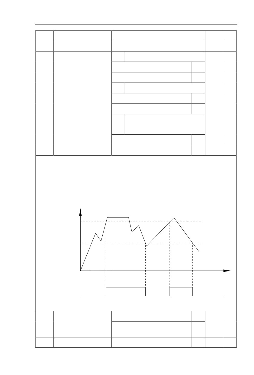
AI is used as DI for this function group. AI input voltage is greater than 7V, corresponding AI terminal
state is high level. AI input voltage is less than 3V, corresponding AI terminal state is low level. 3V~7V for
hysteresis loop .
Whether AI (as DI) high level valid or low level valid is determined through function code A1.10. For
AI(as DI) function settings, they are same with common DI settings, for details please refer to P4 group .
Fig. 5-31 takes AI input voltage as an example, explains the relationship between AI input voltage and
corresponding DI state:
AI input voltage
DC7V
DC3V
t
ON
ON
OFF
AI terminal status
Fig.5-31AI terminal valid state schematic diagram
Short circuit with physics DIx internals
0
A1.11
Virtual VDO1 output function
0
☆
See P5 group for physics DO output
1~40
selection
A1.12
Virtual VDO2 output function
Short circuit with physics DIx internals
0
0
☆
127