HV590L Series Frequency Inverter. User Manual (Version: 3.1.14) - page 2
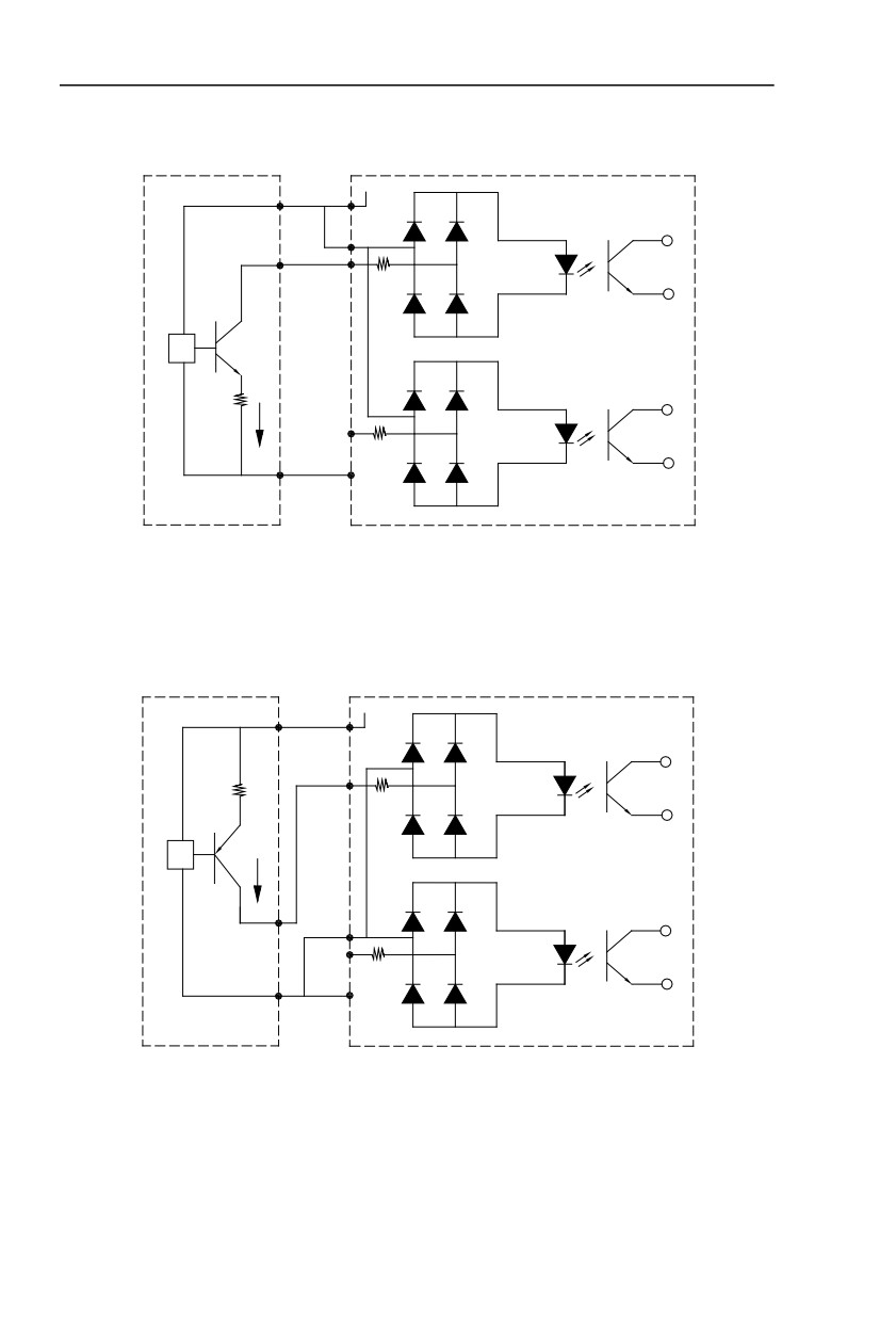
It is recommended to use the contact control mode.
a) DI terminal wiring method (The drain wiring mode)
+24V
+VCC
+24V
SP
Signal
DI1
4.7K
NPN
3.3Ω
DI5
4.7K
0V
COM
External controller
Inverter control board
Fig.2-6.3 Drain wiring mode
This is one of the most commonly used connection mode. If you use an external power
supply, J9 jumper must be removed, and connect the external positive power supply to SP,while
negative power supply to DI port.
b)DI terminal wiring method (The source wiring mode)
+24V
+VCC
+24V
3.3Ω
DI1
4.7K
PNP
Signal
SP
DI5
4.7K
0V
COM
External controller
Inverter control board
Fig. 2-6.4 Source wiring mode
This connection mode must make SP of jumper J9 connect to COM port,and connect +24V
and public terminal of external controller together.If you use an external power supply,jumper J9
must be removed,and connect external negative power supply to SP ,while positive power
supply to DI port.
3) Digital output terminal
32
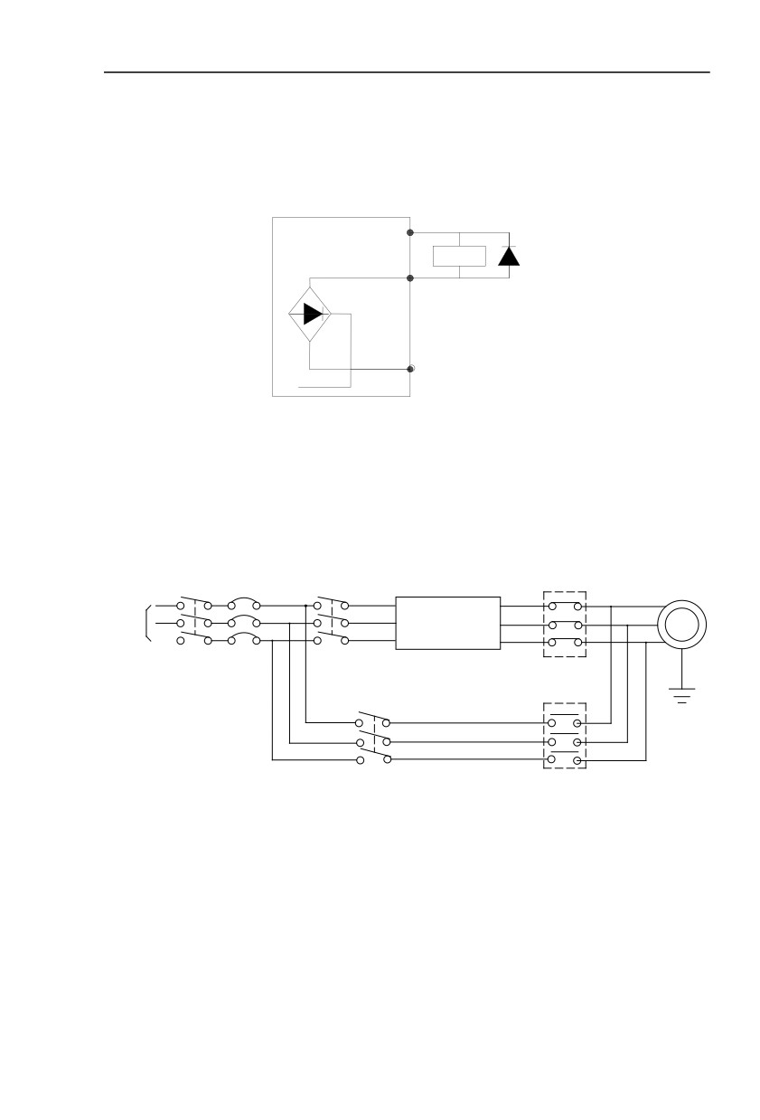
When drive relay is essencial for digital output terminal,you should add absorption diode to
both sides of relay coil.Or +24V dc power supply will be easily damaged.
Caution: The polarity of the absorption diode must be installed correctly according to the
picture below.Or +24V dc power supply will immediately get burnt after digital output terminal
outputs.
+24V
HV590L
Relay
Diode
DO
COM
Fig. 2-6.5 Digtal output terminal wiring diagram
2.7 Standby circuit
Inverter fault or jump may cause great breakdown loss or other accident. To avoid this
happens, please add the standby circuit below to ensure security.
Note:Confirm and test the running characteristic of the standby circuit, make sure that the
industrial phase and the converter phase are in the same direction.
MCC1
R
R
U
S
S
V
M
T
T
Inverter
W
3~
3-phase AC power supply
Interlock AC contactor
MCC2
Fig. 2-7.1
33
Section III. Fittings
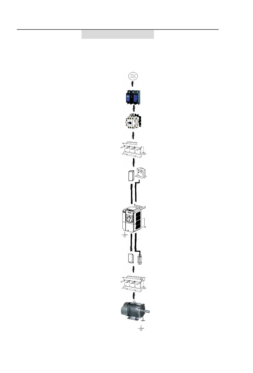
3.1 Connection with peripheral devices
3.1.1 Connection of the Product and Peripheral Devices
Power supply
Circuit breaker or
leakage circuit breaker
Contactor
Input AC reactor
Input noise filter
DC reactor
Inverter
Grounding
Output noise filter
Braking resistor
OutputAC reactor
Motor
Fig.3−1 Connection diagram of the product and peripheral devices
34

3.1.2 Peripheral Electric Parts of HV590L
PartName
InstallationLocation
FunctionDescription
The
front-end
of
Disconnectthepowersupplyincaseof
Circuit breaker
theinputcircuit
downstreamequipment isovercurrent
Power-onandpower-offoftheinverter.Frequent
Between the circuitbreaker
Contactor
power-on/power-off operation(at least once per
andthe inverterinputside
minute) on the inverter should be avoided
Improve the power factor of the input side:
1.Eliminate the high order harmonics of the input
side effectively, and prevent other equipment from
AC input reactor
Inputsideof the inverter
damagingdue to voltage waveform deformation.
2.Eliminate the unbalancedinput current due to
theunbalancedpowerphases.
1.Reduce the external conduction and radiation
interference of the inverter;
2.Reduce the conduction interference flowing from
thepower end to the inverter, thus improving the
anti-interference capacity of the inverter.
3.The common size of 3-phase EMI noise filter is
shown as following: confirm the power supply is
3-phase three lines or 3-phase four lines or single
EMCinputfilter
Input side ofthe inverter
phase. Grounding wire is as short as possible, try
to place the filter near the converter.
Please choose EMI filter when the inverter is used
in residential area, commercial area, science area
as well as situations where higher demand to
prevent radio interference is needed or meeting
CE、UL、CSA standard but existing equipment that
anti-interference ability is not sufficient.
If needing the filter, please connect with the company.
Improve the power factor of the input side:
1.Improvethe overall efficiency and thermal stability
HV590L series can adopt
2.Effectively reduce the influence of high order
DCreactor
external DC reactor
harmonicsat the input side on the inverter and
according to the need.
reduce the external conduction and radiation
interference.
The inverter output side generally has higher
harmonic.When the motor is far from the inverter,
Between the inverter output
since there are many capacitors in the circuit,
side and the
certain harmonics will cause resonance in the circuit
ACoutput reactor
motor,closetothe inverter
and bring in the following results:
1.Degrade the motor insulation performance and
damagethe motor for the long run
2.Generatelarge leakage current and cause frequent
35

inverter protection action
3.In general, if the distance between the inverter
and themotor exceeds 100 meters, output AC
reactor should be installed
Between the inverter output
The fittings can restrain the disturbance noise and
Output EMI filter
side and the motor,closetothe
lead line leak current produced in the output side.
inverter
Table:3-1.1
36
3.2 Mounting hole dimension
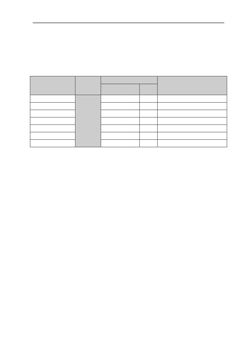
3.2.1 Braking unit & Braking resistance
When customers choose the type with braking,there will be braking unit inside the
inverter,maximum braking torque is 50%.Please refer to the table below and choose the matched
braking resistance separately.
Braking unit
Braking
Shape DIM
Quanti
Braking moment %
unit
Braking
ty
HV590L−004G3
400W
150Ω
1
135
HV590L−5R5G3
500W
100Ω
1
135
HV590L−7R5G3
800W
75Ω
1
130
Standard
HV590L−011G3
1040W
50Ω
1
135
built-in
HV590L−015G3
1560W
40Ω
1
125
HV590L−018G3
4800W
32Ω
1
125
HV590L−022G3
4800W
27.2Ω
1
125
Table:3-2.1
If you need accessories in the table,please declare in order.
For larger built-in braking torque,please use the HNC braking unit.do ou can refer to HNC
braking unit manual for details.
Other large power modelsdo not contain a built-in braking.If large power model need to be
equipped with braking function,please choose HNC braking unit.
External DC reactor installation:
For HV590L series inverter, external DC reactor can be ordered according to your
needs.When installation,you should tear down copper platoon between DC+1 and DC+2 of
inverter main circuit.And then add reactor between DC+1 and DC+2,wiring between reactor
terminals and inverter terminals DC+1 and DC+2 have no polarity. After installation of dc
reactor,short circuit copper platoon between DC+1 and DC+2 is no more used.
37
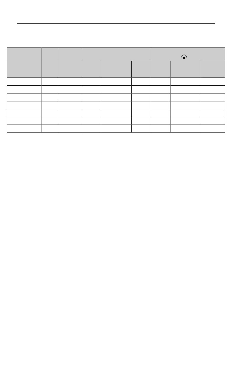
3.2.2 Specifications of circuit breaker、cable and contactors
Terminal screwPE
R、S、T、⊕、B、Ө、U、V、W
breaker
contactor
Shape DIM
wiresta
Wire
(A)
(A)
Terminal
Fastening
Termina
Fastening
ndard(
standard(
screw
Moment(N·m)
l screw
Moment(N·m)
mm2)
mm2)
HV590L−004G3
25
16
M4
1.2~1.5
4
M4
1.2~1.5
4
HV590L−5R5G3
32
25
M4
1.2~1.5
6
M4
1.2~1.5
6
HV590L−7R5G3
40
32
M4
1.2~1.5
6
M4
1.2~1.5
6
HV590L−011G3
63
40
M5
2.5~3.0
6
M5
2.5~3.0
6
HV590L−015G3
63
63
M5
2.5~3.0
6
M5
2.5~3.0
6
HV590L−018G3
100
63
M6
4.0~5.0
10
M6
4.0~5.0
10
HV590L−022G3
100
100
M6
4.0~5.0
16
M6
4.0~5.0
16
Table:3-2.3
38
Section IV. Keyboard Operation
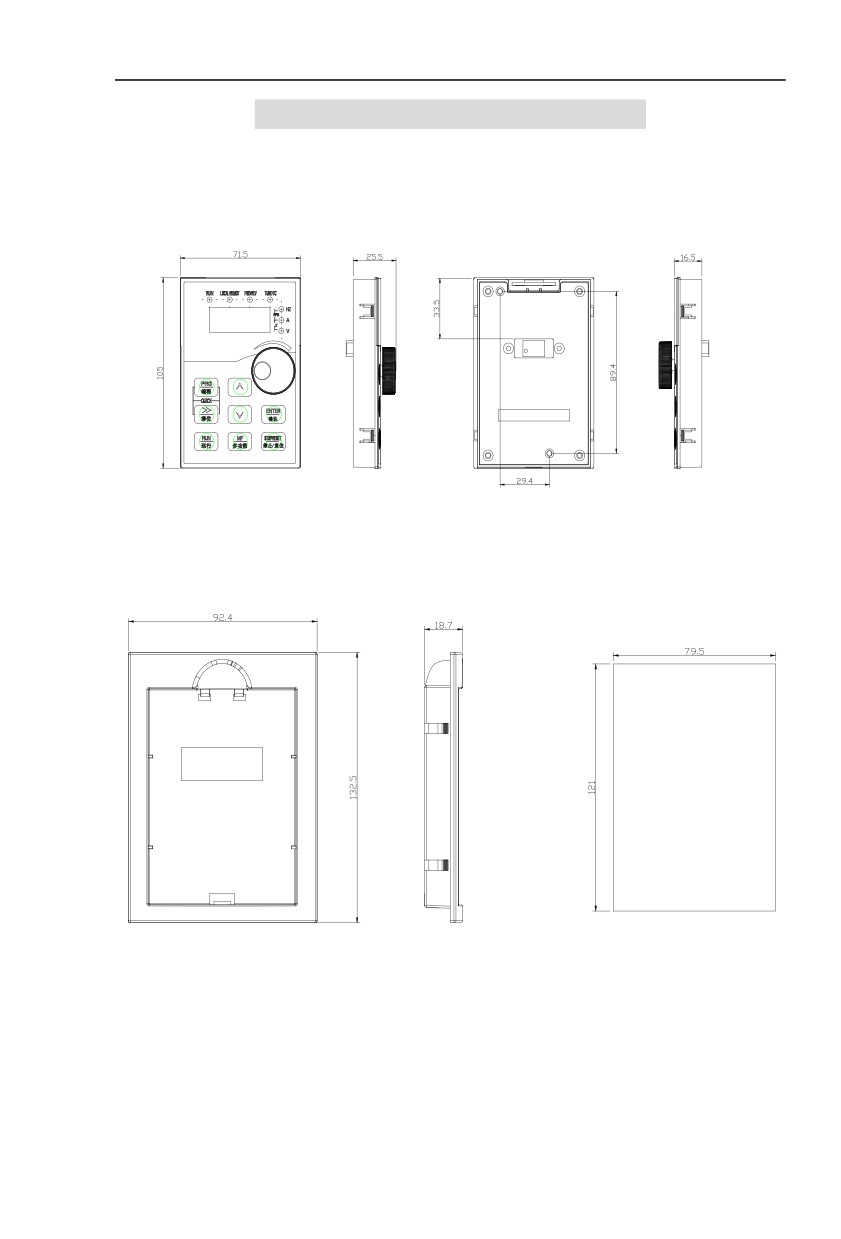
4.1 Keyboard size
4.1.1 HV590L keyboard specification
50.000
Fig. 4-1.1
4.1.2 Keyboard warehouse JP3 dimension
Fig. 4-1.2
39
4.2 Display Interface
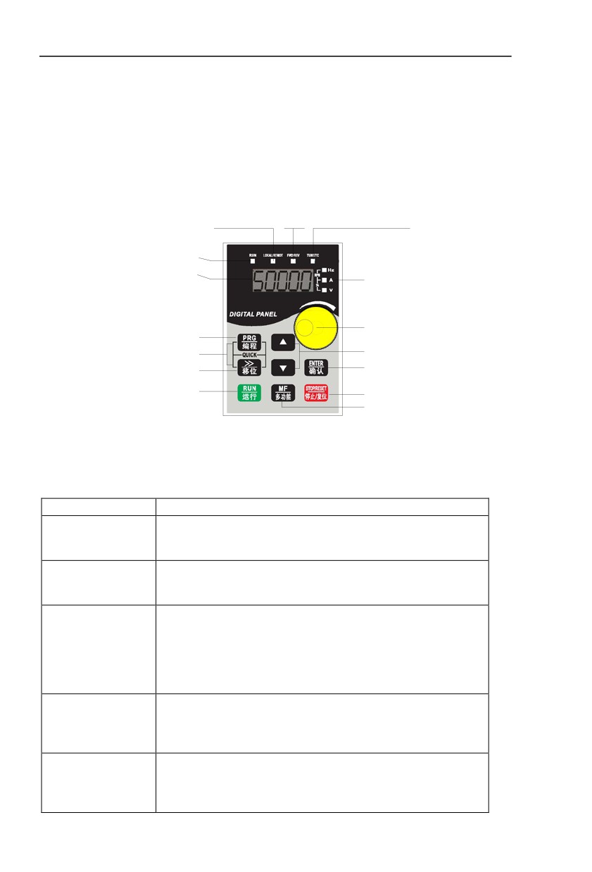
Modification of function parameter, monitoring of inverter operation, control of inverter
operation (start and stop) can be performed through the operation panel.Its shape and function
area are shown as below:
Command source indicator light
FWD/REV indicator light Tune/fault indicator light
On:Terminal operation control state
On:forward rotation
on:torque control mode
Off:keyboard operation control state
off:reverse rotation
slow flashing:Tunning state
Flashing:Remote operation control state
Fast flashing:Fault state
Running indicator light
on:Running state
Unit indicator light
off:stop state
Hz:Frequency
Data display
A:Current
V:Voltage
RPM(Hz+A):Revolving speed
%(A+Z):Percentage
Potentiometer
Programming
Increasing key
Menu mode selection key
Decreasing key
Shift key
Enter key
Running key
Stop/reset key
Miult-function selection key
Fig. 4-2.1
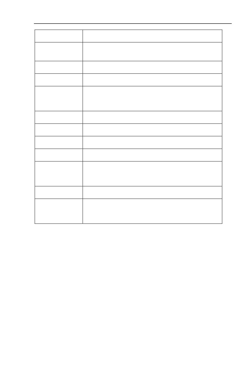
4.2.1 Function description of operation panel
Keyboard Parameter
Description
Forward/Reverse Running Light
FWD/REV
*ON:forward running
*OFF:reverse running
Running indicator
RUN
*ON:running state
*OFF:stop state
Command source indicator
keyboard operation, terminal operation and remote
operation(communication control) indicator
LOCAL/REMOT
*ON:terminal operation control state
*OFF:keyboard operation control state
*Flashing:remote operation control state
Tuning/Fault indicator
*ON:torque control mode
TUNE/TC
*Slow flashing:tuning state
*Quick flashing:fault state
Unit indicator
Hz A V
* Hz frequency unit
RPM(Hz+A)
*A current unit
%(A+V
*V voltage unit
40
*RMP(Hz+A)revolving speed unit
*%(A+V)percentage
Digital display area
Digital display
*5-bit LED display,monitor set frequency,output frequency,various monitoring
data,alarm code etc.
PRG+>>/SHIFT=QUIC
Menu mode selection code,shift different menu mode according to the value
K
of PP.03 (Function parameter mode as default)
Programming key
PRG
*Primary menu enter or exit
Shift key
*On the stop display interface or running display interface, it can be used to
>>/SHIFT
circularly select the display parameters. When modifying the parameters, it
can be used to select the bits of parameter for modification
Confirmation key
ENTER
*Gradually step into the menu screen,set parameters confirmation
Increasekey
∧
*Increaseofthedataorfunctioncode
Decreasekey
∨
*Decreaseofthedataorfunctioncode
Multi-function selectionkey
MF/REV
*ItisusedasfunctionswitchingselectionaccordingtoP7.01.
Potentiometer
* P0.03 is set to 4 as default;
Potentiometer
* Control board jumper J6 is in 1-2,keyboard potentiometer set frequency
* Control board jumper J6 is in 2-3, AI3 terminal set frequency
Runningkey
RUN
* Itisusedtostart the runningoftheinverterunderkeyboard controlmode
Stop/reset
Inrunningstatus,it
canstoptherunningbypressingthiskey.
STOP/RESET
Inalarmstatus,itcan reset operation with this key. The characteristics of this
key are limited by function code P7.02.
Table 4-2.1
41
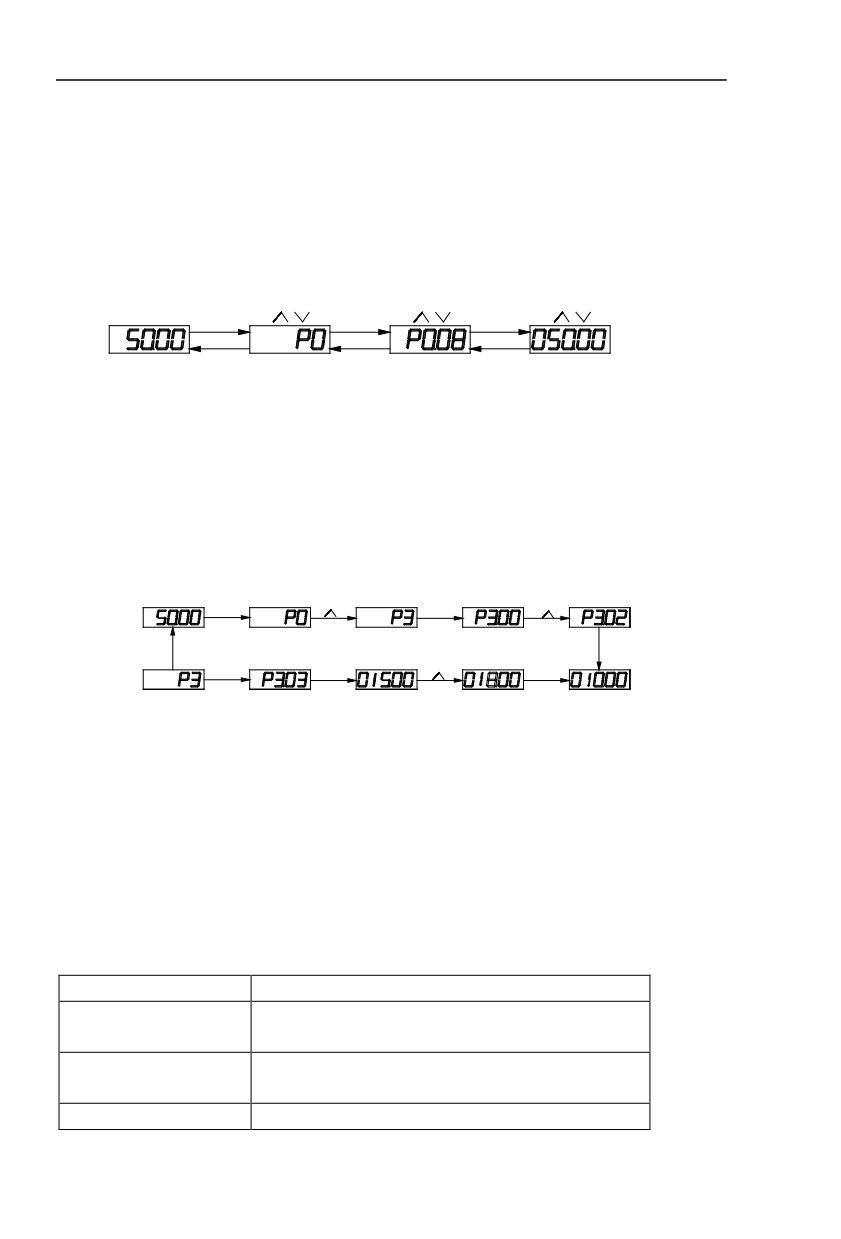
4.3 Examples for parameter setting
4.3.1 Description of function code viewing and modificationmethod
TheoperationpanelofHV590Linverteradoptsthree-levelmenustructure to perform parameter
setting.The
three-levelmenuincludes
: functionparametergroup(level1menu)→
functioncode(level2menu)→settingvalueof function code(level3 menu).The operation process is
as shown in Figure below.
Parameter set
Function parameter
Function parameter
modification
choice modification
value modification
PRG
ENTER
ENTER
PRG
PRG
ENTER
level 0 menu
level 1 menu
level 2 menu
level 3 menu
PRG
Figue 4-3.1
Caution: When operating on level 3 menu, press PRG key or ENTER key to return to level
2 menu. The difference between ENTER and PRG keys is that pressing ENTER KEY will
save the setup parameter and return to level 2 menu and then automatically shift to the next
function code, while pressing PRG key will directly return to level 2 menu without saving the
parameter, and it will return to the current function code.
Take the modification of function code P3.02(ranging from 10.00Hz to 15.00Hz ) as an
example. (The boldface bit indicates the flashing bit).
PRG
ENTER
PRG
ENTER
PRG
ENTER
>>SHIFT
Figue 4-3.2
In level 3 menu, if the parameter has no flashing bit, it indicates that the function code
cannot be modified. The possible reasons include:
1) The function code is an unchangeable parameter, such as actual detection parameter,
running record parameter, etc.
2) The function code cannot be modified in running status but can be modified after the
unit is stopped.
4.3.2 Parameter display mode
Parameter display mode is mainly established to view different arrangement forms of
function parameters according to user’s actual needs.3 kinds of display mode:
Name
Description
Sequence display inverter function parameters ,there are
Function parameter mode
P0~PF、A0~AF、U0~UF fuction groups respectively.
User set individual function parameters(32 at most), parameters
User set parameter mode
that needed to be displayed can be set through PE group
User modify parameter mode
Inconsistent with factory default parameters
Table 4-3.1
42
Relevant function parameters PP.02、PP.03, set as below:
Parameters display mode
Default
11
attributes
value
1bit
U group display selection
0
No display
PP.02
1
Display
Set range
10bit
A group display selecton
0
No display
1
Display
Individual parameter mode
Default
00
display selection
value
1bit
User set parameter display selection
0
No display
PP.03
1
Display
Set range
10bit
User modify parameter display selection
0
No display
1
Display
Table 4-3.2
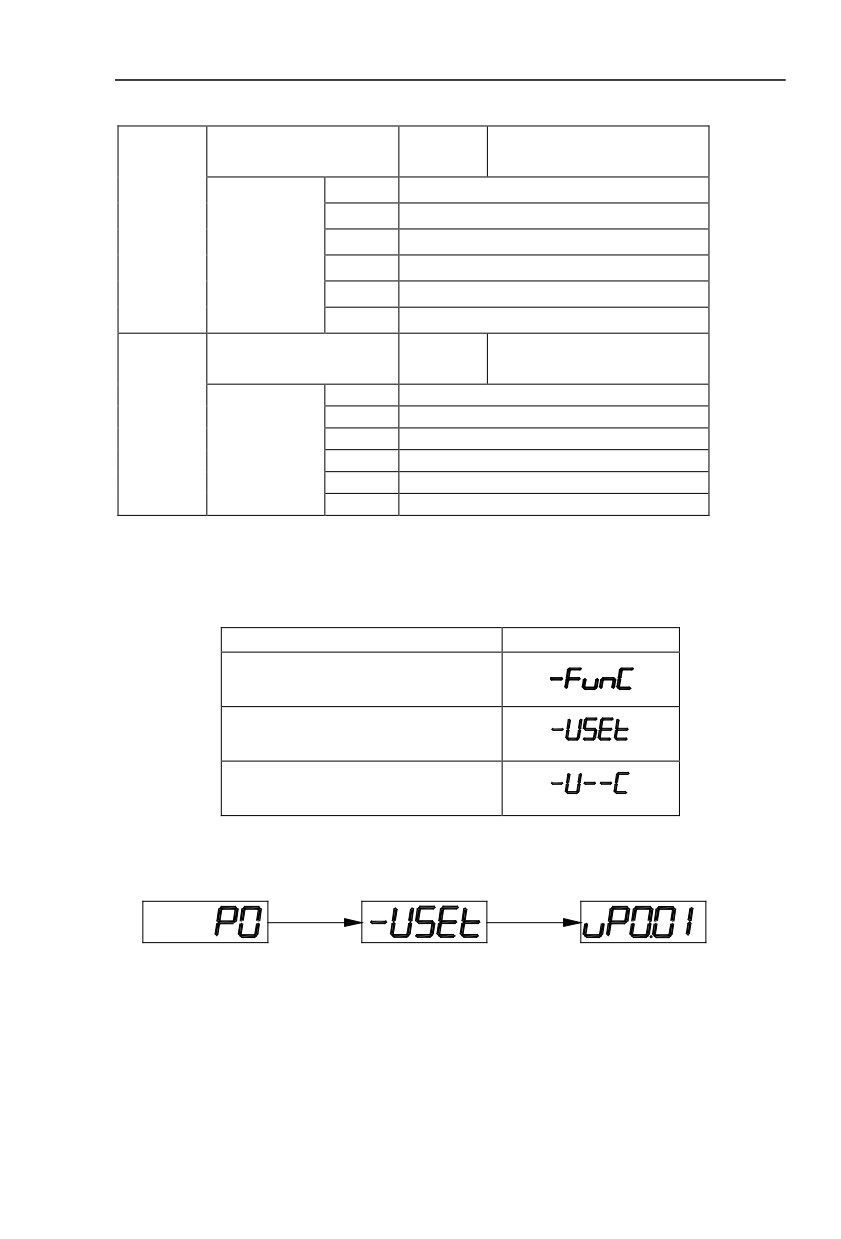
When there is 1bit display existing in the individual parameter mode display selection(PP.03),
you can enter different parameter display mode by pressing PRG+>>/SHIFT key at the same time.
Each parameter display codes:
Parameter display mode
Display
Function parameter mode-FunC
User set parameter mode -USEt
User modify parameter mode -U--C
Table 4-3.3
Switching mode as below:
E.g:To switch current function parameter mode to user set parameter mode.
PRG+>>SHIFT
ENTER
Fig. 4-3.3
4.3.3 User set parameter operation mode
User set menu is established for quick checkup and modification. The display mode is
“uP3.02”,which represents function parameter P3.02. It has the same effect of modifying
parameter in user set menu and normal programming state.
Function parameters of user set menu come from PE group.PE group chooses function
43
parameter:when PE is set to P0.00 ,it means no choosing,totally 30 functions can be set. If
display “NULL” when entering menu, it means user set menu is null.
16 parameters have been stored at initial time for user’s convenience:
P0.01:Control mode
P0.02:Command source selection
P0.03:Main frequency source selection
P0.07:Frequency source selection
P0.08:Preset frequency
P0.17:Acceleration time
P0.18:Deceleration time
P3.00:V/F curve set
P3.01:Torque boost
P4.00:DI1Terminal function selection
P4.01:DI2terminal function selection
P4.02:DI3 terminal function selection
P5.04:DO1output selection
P5.07:AO1 output selection
P6.00:Startup mode
P6.10:Stop mode
Users could modify the user set parameter according to specific need of your own.
4.3.4 Check method of state parameter
When the inverter is in stop or running status, multiple status parameters can be displayed.
It can select if this parameter is to be displayed in binary bit with the function codes P7.03
(running parameter1) , P7.04 (running parameter2) and P7.05(stop parameter).
In stop status, there are 4 running state parameter:set frequency, bus voltage,analog
input voltage AI1, analog input voltage AI2 which of them are of default display.Other display
parameters respectively:DI input state,DO output state,analog input voltage AI3, actual count
value, actual length value, PLC running steps, load speed display, PID set, PULSE input pulse
frequency and 3 reserved parameters (whether to display or not is determined by function code
P7.05 binary bit choice). Selected parameter are switched in sequence order.
In running status, there are a total of
5 running status parameters, including:setup
frequency, running frequency, bus voltage,output voltage,output current ,which of them are of
default display. Other display parameters respectively :output power, output torque, DI input
state,DO output state, analog input voltage AI1, analog input voltage AI2, analog input voltage
AI3, actual count value, actual length value, linear velocity, PID set, PID feedback etc. Whether
to display or not is determined by function code P7.03、P7.04 binary bit choice. Selected
parameter are switched in sequence order.
When inverter power on after powered off , the display parameter is the one that chosen
before power off as default.
4.3.5 Password Setting
The inverter provides user password protection function. When PP.00 is set to non-zero
value, it is user password and enabled after exiting the function code editing status. When the
user presses the PRG key again, “-----“will be displayed to require the user to enter user
password, or the user cannot enter the general menu.
To cancel the password protection function, the user needs to enter the relevant interface
through password, and change the PP.00 setting to 0.
44

4.3.6 Motor parameter automatic tuning
Vector control running mode:before running, user must accurately input motor nameplate
parameters. HV590L series inverter will be matching standard motor parameter according to
this nameplate. Vector control methods are very much dependent on motor parameters, to get
good control performance, accurate control motor parameters must be acquired.
Motor parameter auto tuning procedure is as follows:
Firstly, select command source(P0.02) as operation panel command channel.Secondly,
input parameters below in accordance with motor actual parameter:
Motor selection
Parameter
P1.00:Motor type selection
P1.01:Motor rated power
Motor 1
P1.02:Motor rated voltage
P1.03:Motor rated current
P1.04:Motor rated frequency
P1.05:Motor rated revolving speed
A2.00:Motor type selection
A2.01:Motor rated power
Motor 2
A2.02:Motor rated voltage
A2.03:Motor rated current
A2.04:Motor rated frequency
A2.05:Motor rated revolving speed
A3.00:Motor type selection
A3.01:Motor rated power
Motor 3
A3.02:Motor rated voltage
A3.03:Motor rated current
A3.04:Motor rated frequency
A3.05:Motor rated revolving speed
A4.00:Motor type selection
A4.01:Motor rated power
Motor 4
A4.02:Motor rated voltage
A4.03:Motor rated current
A4.04:Motor rated frequency
A4.05:Motor rated revolving speed
Table 4-3.4
E.g:Asynchronous motor parameter tuning
If motor and the load can be totally separated, please select P1.37(Motor
2\3\4 as
A2\A3\A4.37) to 2(Asynchronous machine complete tuning), then press RUN key on keyboard
panel, inverter will automatically calculate the motor of the following parameters:
Motor selection
Parameter
P1.06:Asynchronous motor stator resistance
P1.07: Asynchronous motor rotor resistance
Motor 1
P1.08: Asynchronous motor leakage inductance
P1.09: Asynchronous motor mutual inductance
P1.10: Asynchronous motor no-load current
A2.06: Asynchronous motor stator resistance
Motor 2
A2.07: Asynchronous motor rotor resistance
45
A2.08: Asynchronous motor leakage inductance
A2.09: Asynchronous motor mutual inductance
P2.10: Asynchronous motor no-load current
A3.06: Asynchronous motor stator resistance
A3.07: Asynchronous motor rotor resistance
Motor 3
A3.08: Asynchronous motor leakage inductance
A3.09: Asynchronous motor mutual inductance
P3.10: Asynchronous motor no-load current
A4.06: Asynchronous motor stator resistance
A4.07: Asynchronous motor rotor resistance
Motor 4
A4.08: Asynchronous motor leakage inductance
A4.09: Asynchronous motor mutual inductance
P4.10: Asynchronous motor no-load current
Table4-3.5
If motor and the load can not be totally separated, please select P1.37(Motor 2\3\4 as
A2\A3\A4.37) to 1(Asynchronous machine static tuning), then press RUN key on keyboard panel.
4.4 Test running
HV590L General machine type factory setting value
Code
Factory setting
Description
P0.01
0
Speed sensorless vector control(SVC)
P0.02
0
Operation panel command channel(LED OFF)
P0.03
4
AI3(Potentiometer)
Users set motor parameters P1.00~P1.05 to correct values, after parameters auto tuning,
motor operation can be directly controlled through keyboard, while frequency can be set through
keyboard potentiometer.
46

Section V. Parameter Function Table
Caution:
The symbols in the function table are explained as follows:
“★”:indicates that the parameter setup value cannot be modified when the inverter is in the
running status.
“●”:indicates that the parameter value is the actual detection record and cannot be modified.
“☆”:indicates that the parameter setup value can be modified when the inverter is in stop
status and running status.
“▲”:indicates that the parameter is “Factory default parameter” and can be set only by the
manufacturer, and the user is forbidden to perform any operation.
“-”:indicates that the parameter factory value is relevant to power or model, for specifications
please refer to corresponding parameter description.
“Change limit” indicates if the parameter is adjustable during operation.
When PP.0 is set to non-zero value, it means that the parameter protection password is set
and only when correct password is input can the user enter the parameter menu. To cancel the
password, PP.00should be set to 0.
In the user set parameter mode , parameter menu is not protected by password protection.
P group, A group are of basic function parameters, U group is the monitor function group.
5.1 Monitor function group:U0.00-U0.61
U0 parameter group is used to monitor inverter running status .Customers can check through
panel for field commissioning as well as read parameter value through communication for position
machine monitoring. Among which, U0.00~U0.31 is defined for running or stop monitor parameter
by P7.03 and P7.04.
For specific parameter function code、parameter name and minimum unit, please refer to the
table below.
Function code
Designation
Unit
U0.00
Running frequency(Hz)
0.01Hz
Inverter current actual setting frequency
U0.01
Setting frequency(Hz)
0.01Hz
Inverter current actual output frequency
U0.02
DC bus voltage(V)
0.1V
Detection value of DC bus voltage
U0.03
The output voltage(V)
1V
Inverteractual output voltage
U0.04
Motor output current(A)
0.01A
47
Valid value of motor actual current
U0.05
The output power(kW)
0.1kW
The calculated value of actual output power of motor
U0.06
Output torque(%)
0.1%
The output torque of the motor
U0.07
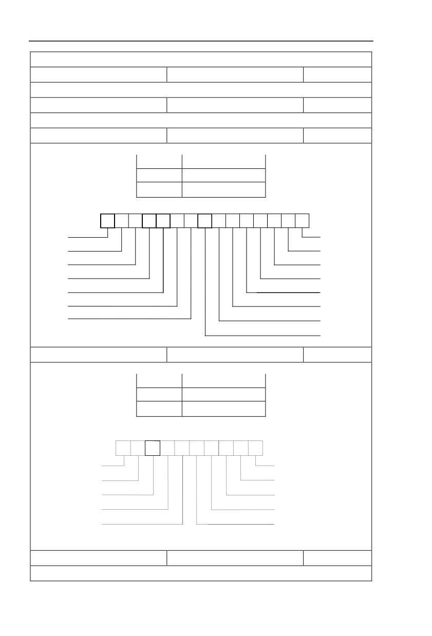
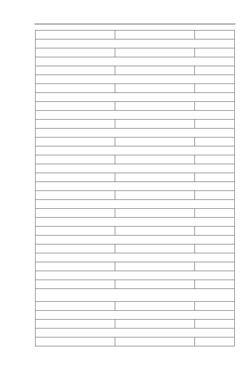
DI input status
1
IO input status,it’s value is a hexadecimal digit.Each bit corresponds to each input terminal state:
0~14 bit
Input status
0
Invalid
1
Valid
14
13
12
10
9
8
7
6
5
4
3
2
1
0
2
2
2
211
2
2
2
2
2
2
2
2
2
2
2
14
13
12
11
10
9
8
7
6
5
4
3
2
1
0
VDI5
DI1
VDI4
DI2
VDI3
DI3
VDI2
DI4
VDI1
DI5
DI10
DI6
DI9
DI7
DI8
U0.08
Y output status
1
IO output status,it’s value is a hexadecimal digit.Each bit corresponds to each output terminal state :
0~9 bit
Output status
0
Invalid
1
Valid
9
7
6
5
4
3
2
1
0
2
28
2
2
2
2
2
2
2
2
9
8
7
6
5
4
3
2
1
0
VDO5
Y1R
VDO4
TA1-TB1-TC1
VDO3
TA2-TB2-TC2
VDO2
DO1
VDO1
DO2
U0.09
AI1 voltage(V)
0.01V
AI1 input voltage, corrected by AC.00~AC.03
48
U0.10
AI2 voltage(V)
0.01V
AI2 input voltage, corrected by AC.04~AC.07
U0.11
AI3 voltage(V)
0.01V
AI3 input voltage, corrected by AC.08~AC.11
U0.12
Count value
1
Fb function group count function Pb.08~Pb.09
U0.13
Length value
1
Fb function group fixed length function Pb.05~Pb.07
U0.14
Load speed display
1
Motor actual running speed
U0.15
PID set point
1
PID percentage of reference value for running adjustment.
U0.16
PIDfeedback
1
PID percentage of feedback value for running adjustment.
U0.17
PLC stage
1
PLC program running stage-display
U0.18
PULSE pulse input frequency(kHz)
0.01kHz
Display PULSE pulse input frequency,unit 0.01Khz
U0.19
Speed feedback(Unit 0.1Hz)
0.1Hz
synchronous speed,accurate to 0.1hz
U0.20
Surplus running time
0.1Min
Display surplus running time, used for regular operation control.
U0.21
AI1 voltage before correction
0.001V
AI1 voltage before correction ,used for AC function group parameter AC.00~AC.03 to correct AI1 voltage
U0.22
AI2 voltage before correction
0.001V
AI2 voltage before correction ,used for AC function group parameter AC.04~AC.07 to correct AI2 voltage
U0.23
AI3 voltage before correction
0.001V
AI3 voltage before correction ,used for AC function group parameter AC.08~AC.11 to correct AI3 voltage
U0.24
Linear velocity
1m/Min
Linear velocity is calculated according to angular velocity and diameter, used for constant tension control
and constant linear velocity control.
U0.25
Current power on time
1Min
The cumulative power on time of the inverter.
U0.26
Current running time
0.1Min
The cumulative running time of the inverter.
U0.27
PULSE pulse input frequency
1Hz
49

Display PULSE pulse input frequency ,unit 1Hz.
U0.28
Communication set value
0.01%
Communication set value
U0.29
Encoder feedback speed
0.01Hz
PG feedback speed, accurate to 0.1hz
U0.30
Main frequency X display
0.01Hz
P0.03 main frequency source set frequency
U0.31
Auxiliary frequency Y display
0.01Hz
P0.04 auxiliary frequency source set frequency
U0.32
View arbitrary memory address value
1
To view arbitrary memory address, advanced commissioning function.
U0.33
Reserve
0.0°
U0.34
Motor temperature
1℃
Display motor temperature. Other device temperature can also be tested through different temperature
measuring point.
U0.35
Target torque(%)
0.1%
Target torque setup.In torque control mode, it is used to check the set target torque.
U0.36
Rotary variable position
1
It’s rotor position when speed feedback.
U0.37
Power factor angle
0.1
Current power factor angle,power factor=COS(angle),angle=0,maximum power.
U0.38
ABZ position
0.0
ABZ incremental feedback position information of encoder calculation.
U0.39
VF target voltage separation
1V
VF target voltage when power supply separating.
U0.40
VF output voltage separation
1V
VF output voltage when power supply separating.
U0.41
DI input status intuitive display
-
50
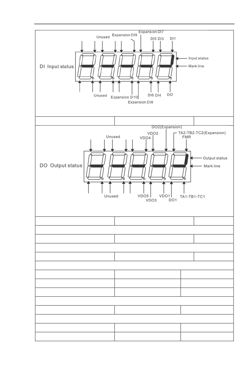
Display DI input status intuitively, offer DI input information more detailed than U0.07, advanced
display function.
U0.42
DO output status intuitive display
-
Display DO output status intuitively, offerDO output information more detailed than U0.08, advanced
display function.
U0.43
DI function status intuitive display1
1
Display DI function status 1 intuitively ,display(function 01-40)
U0.44
DI function status intuitive display2
1
Display DI function status 2 intuitively ,display (function 41-80)
U0.45
Fault information
0
Fault information query.
U0.46
Reserved
-
U0.47
Reserved
-
U0.48
Reserved
-
-100.00%~100.00%
U0.60
Running frequency(%)
0.01%
-100.00%~100.00%
U0.61
Inverter status
1
51
U0.62
Current fault code
1
U0.63
Point to point communication
0.01%
U0.64
From the number of stations
1
U0.64
Torque limit
0.01%
5.2 Basic function group:P0.00-P0.28
FactoryChange
Code
Description/Display
Setting Range
Setting
Limit
G type(constant torque load type)
1
P0.00
GP type display
-
●
P type(draught fan,pump load type)
2
This parameter is only for the use of viewing the factory model. It is can not be modified.
1:It is applicable to the constant torque load of specified rated parameter
2:It is applicable to the variable torque load of specified rated parameter(draught fan,pump load type)
Speed sensorless vector control(SVC)
0
P0.01
Motor 1 control mode
Speed sensor vector control(FVC)
1
2
★
V/F control
2
0:Speed sensorless vector control
It refers to the open-loop vector control that is generally applied to high performance control field. One
inverter can only drive one motor. E.g:machine tool, centrifugal machine, fiber drawing machine, injection
molding machine’ load etc.
1:Speed sensor vector control
It refers to the closed-loop vector control and encoder must be added to the motor end.Inverter must
be matching with the same type PG card of the encoder. This control mode is suitable for high precision
speed control and torque control field. One inverter can only drive one motor. E.g : high speed
papermaking machinery , hoisting machinery , elevator’load etc.
2:V/F control
V/F control mode is suitable for fields that load demand is not high or one inverter can drive multiple
motos. E.g:draught fan, pump’ load etc.
Tips:Motor parameters must be indentified before choosing vector control mode.Only accurate motor
parameters can play the advantage of vector control mode. Users can get better performance by adjusting
speed regulator group P2 parameters(motor 2,motor 3,motor 4 respectively for group A2,A3,A4)
FVC is generally used for permanent magnet synchronous motor, while part of the small power
applications can select V/F control mode. HV590L series support specific models of permanent magnet
synchronous motor sensorless vector control mode. Please refer to HV590L users manual and HV590LS
dedicated users manual for using method.
Operation panel command channel(LED
P0.02
Command source selection
0
1
☆
off)
52
Terminal command channel(LED on)
1
Serial port communicationcommand
2
channel(LED flashing)
Inverter control commands include: run, stop, forward rotation (FWD), reverse rotation (REV),
forward jog (FJOG), reverse jog (RJOG), etc.
0: Operation panel command channel (“LOCAL/REMOT” LED off);
Perform running command control with RUN, MF.K and STOP/RESET keyson the operation panel.
1: Terminal command channel (“LOCAL/REMOT” LED on);
Perform running command control with multifunctional input terminals such as FWD, REV, FJOG,
RJOG, and so on.
2:Serial port communication command channel (“LOCAL/REMOT” LED flashing).
The running command is given by the host computer via the communication mode. When the item is
choosen,it must be equipped with communication card(Modbus RTU 、 ProfibusDP card 、 users
programmable control card or CANopen card and so on).
For the communication protocol, please refer to
“PD group communication parameters”and
supplementary explanation of corresponding communication card for details.
Supplementary explanation for communication card is allotted with communication card.This manual
contains a brief description of communication card.
Digital setup(Preset frequency P0.08,
UP/DOWN can be modified, power off
0
without memory)
Digital setup(Preset frequency P0.08,
UP/DOWN can be modified, power off
1
with memory)
AI1
2
Main frequency source X
AI2
3
P0.03
6
★
selection
AI3(Potentiometer)
4
Pulse setup(DI5)
5
MS command
6
Simple PLC
7
PIDsetup
8
Communicaton setup
9
This parameter is used to select the main reference frequency input channel. Totally 10 main reference
frequency channels:
0:Digital setup(power off without memory)
Initial value of set frequency equals to P0.08
“preset frequency”.User can change inverter set
frequency value through keyboard ∧ key and ∨ key ( or multi-function input terminal UP,DOWN).
Inverter power on after powered off, frequency set value restored to P0.08 “Preset frequency”.
1:Digital setup(power off with memory)
Initial value of set frequency equals to P0.08
“preset frequency”. User can change inverter set
frequency value through keyboard ∧ key and ∨ key ( or multi-function input terminal UP,DOWN).
Inverter power on after powered off, frequency set value restored to the value that equals to setupof
last power off time. Correction is memorized through keyboard ∧ key and ∨ key or terminal UP,DOWN.
What needs to be reminded is, P0.23 is “Digital setup frequency memory selection”. P0.23 is used to
select correction whether to be memorized or cleared and is relevant to stop, irrelevant to power off
memory, please pay attention during operation.
53

2:AI1
3:AI2
4:AI3(Potentiometer)
Frequency is determined by analog input terminal. HV590L series control board offers 2 analog input
terminal(AI1,AI2), optional device HNC5PC1 card can offer 1 isolated analog input terminal(AI3x).
AI1,AI2 can be chosen as 0V~10V voltage input as well as 0mA~20mA current input by the jumper
J3,J4 on control board.
AI1、AI2 input voltage value has a corresponding relationship with target frequency, users can choose
them at will. HV590L offers
5 groups of corresponding relation curve, which
3 of them are linear
relationship(2-point correspondence), 2 of them are 4-point correspondence(any curve among them). User
can set through P4 group or A6 function code.
Function code P4.33 is used to set AI1~AI22-channel analog input. Choose 1 curve among the 5
respectively. For specific correspondence please refer to P4、A6 groups.
5:Pulse setup(DI5)
Pulse setup is set through terminal pulse. Signal standard:voltage range 9V~30V, frequency range
0kHz~100kHz. Set pulse can be only input through multi-function input terminal DI5.
Relationship between DI5 input pulse frequency and corresponding settings is set through P4.28~P4.31.
It is linear relationship(2-point correspondence). Pulse input 100.0% refers to the percentage of P0.10 .
6:MS command
MS command running mode is set through different combination mode of digital input DI terminal.
There are 4 MS command terminals with 16 status of HV590L series. PC group function codes correspond
to 16 “MS command”. “MS command” is percentage relativing to P0.10( maximum frequency).
When digital input terminal DI is used as MS command terminal, user should set through P4 group.For
specifications please refer to P4 group.
7:Simple PLC
When frequency source is set to 7, running frequency source can be switched to any frequency
command during 1~16.
User can set frequency command retention time and acceleration/deceleration time respectively.For
specifications please refer to PC group .
8:PID
Running frequency is the output of PID control process. Generally used for field process closed-loop
control.
When PID is choosen, user should set relevant parameters of PA group “PID function”.
9:Communicaton setup
Communication setup refers to main frequency source that setting through communication method of
position machine.
HV590L series support 4 kinds of communication mode:Modbus、Profibus.DP、CANopen 3 kinds of
communication can not be used at the same time.
Communication card should be installed during the use of communication.4 kinds of communication
card are optional.User can select to buy according to the needs, and set parameter P0.28 correctly.
Digital setup(preset frequency P0.08,
UP/DOWN adjustable, power off without
0
memory)
Digital setup(preset frequency P0.08,
Auxiliaryfrequencysource Y
UP/DOWN adjustable, power off with
1
P0.04
0
★
selection
memory)
AI1
2
AI2
3
AI3(Potentiometer)
4
54
PULSE setup (Dl5)
5
MS command
6
Simple PLC
7
PIDsetup
8
Communication setup
9
When the auxiliary frequency source is used as independent frequency reference channel (i.e.
frequency source switching from X to Y), it is used in the same way as the relative specifications of P0.03.
When the auxiliary frequency source is used as overlap reference (i.e. frequency source selection
switching from X plus Y or X to X plus Y), it has special points as follows:
1. When the auxiliary frequency source is digital reference, the preset frequency
(P0.08) is
nonsensical, and it needs to adjust the main reference frequency through the keys “∧”and “∨” of the
keyboard (or UP andDOWN of multifunctional input terminals).
2. When the auxiliary frequency source is analog input reference (AI1、AI2、AI3) or pulse input
reference, 100% of input setup is relative to the auxiliary frequency source range,and can be set through
P0.05 and P0.06.
3. When the frequency source is pulse input reference, it is similar to the analog value.
Prompt: There is difference between the auxiliary frequency source Y selection and the main
frequency source X setup value. That is to say, P0.03 and P0.04 cannot use the same frequency reference
channel.
Auxiliary frequency source
Relative to maximum frequency
0
P0.05
0
☆
Y range selection
Relative to frequency source X
1
Auxiliary frequency source
P0.06
0%~150%
100%
☆
Y range
When the frequency source selection is frequency overlap reference(P0.07 is set to 1、3 or 4), it is
used to determine the adjustment range of auxiliary frequency source. P0.05 is used to determine the
relative object within the range. If it is relative to main frequency, that range will vary with the main
frequency X.
1bit
Frequency source selection
Main frequency source X
0
Main /auxiliary operation result (10bit
1
determine operation relationship)
Switching between X & Y
2
Switching between X & option 1
3
Frequency source
Switching between Y & option 1
4
P0.07
00
☆
stackingselection
Relationship betweenmain
10bit
/auxiliaryfrequency source
Main+auxiliary
0
Main-auxiliary
1
MAX(main frequency source X, auxiliary
2
frequency source Y)
MIN(main frequency source X, auxiliary
3
frequency source Y)
This parameter is used to select frequency setup channel, and of realizing frequency setup through
the compound of main frequency X and auxiliary frequency Y.
55
1bit :Frequency source selection
0:Main frequency source X
Main frequency source X is the target frequency.
1:Main /auxiliary operation result is targe frequency,operation relationship see “10 bit” for details.
2:Switching between main frequency source X and auxiliary frequency source Y
When terminal 18 (frequency switching) is invalid, main frequency X is target frequency. On the
contrary, auxiliary frequency Y is the target frequency.
3:Switching between main frequency X and main /auxiliary operation result
When terminal 18 (frequency switching) is invalid, main frequency X is target frequency. On the
contrary, auxiliary frequency Y is the target frequency.
4:Switching between auxiliary frequency Y and main /auxiliary operation result
When terminal 18 (frequency switching) is invalid, auxiliary frequency Y is the target frequency. On the
contrary, main frequency X is target frequency.
10bit :Relationship between main/auxiliary frequency source
0:Main frequency source + auxiliary frequency source Y
Operation result of main + auxiliary is target frequency. It realizes frequency stacking set function.
1:Main frequency source - auxiliary frequency source Y
Operation result of main - auxiliary is target frequency.
2:MAX(main frequency source X, auxiliary frequency source Y)
Choose bigger absolute value of the two as target frequency
3:MIN(main frequency source X, auxiliary frequency source Y)
Choose smaller absolute value of the two as target frequency.
Besides, when frequency source is main& auxiliary operation,users can set offset frequency through
P0.21.By stacking offset frequency on main& auxiliary operation result,it could flexible cope with all
kinds of needs.
0.00Hz to maximum frequency(It is only valid
P0.08
Preset frequency
50.00Hz
☆
when frequency source is set to “digital setting”)
When set the frequency source to “digital setting” or “terminal UP/DOWN”, the parameter value is the
initial value of the inverter frequency digital setting.
Consistent direction
0
P0.09
Running direction
0
☆
Reverse direction
1
Modification of this parameter can change the rotary direction of the motor without changing any other
parameters, which is equivalent to the role of switching the rotary direction through adjusting any two lines
of the motor (U, V and W).
When needing to change the rotary direction of the motor, users can modify this parameter rather than
adjust the wiring of the motor.
Caution: When the function code is restored to the factory default value, this parameter value is
restored to 0, which should be used prudently in the applications where the motor rotary direction is not
allowed to change.
P0.10
Maximum frequency
50.00Hz~320.00Hz
50.00Hz
★
When analog input, pulse input(DI5), MS command etc are used as frequency source, their respective
100% are relatively calibrated through P0.10.
HV590L maximum frequency could reach 3200Hz. Users can set decimal digits of frequency
command through P0.22 to balance the idex of frequency command resolution and frequency input range.
When P0.22 is set to 1,frequency resolution ratio is 0.1Hz, P0.10 setting range is 50.0Hz~3200.0Hz;
When P0.22 is set to 2, frequency resolution ratio is 0.01Hz, P0.10 setting range is 50.00Hz~320.00Hz.
P0.12 setup
0
P0.11
Frequency source upper limit
0
★
AI1
1
56
AI2
2
AI3(Potentiometer)
3
PULSE setup
4
Communication setup
5
It defines the source of frequency upper limit. Frequency upper limit comes from digital setup (P0.12)
or analog input channel. When upper limt is set through analog input, 100% of analog input corresponds to
P0.12.
E.g : When winding control field is in the torque control mode, to avoid material break
phenomenon,users can set upper limit frequency through analog value. When running frequency reaches
value of upper limit , inverter maintains operation at the upper limit frequency.
Frequency lower limit(P0.14) to maximum
P0.12
Frequency upper limit
50.00Hz
☆
frequency(P0.10)
P0.13
Frequency upper limit offset
0.00Hz~maximum frequency P0.10
0.00Hz
☆
When upper limit is set through analog value or PULSE setup, P0.13 will be used as analog
valueoffset. The addition of offset frequency and analog setup value of frequency upper limit is used as
the final setup value of frequency upper limit.
P0.14
Frequency lower limit
0.00Hz to frequency upper limit P0.12
0.00Hz
☆
When the running frequency of the inverter is lower than the frequency lower limit, it can select to
run at frequency lower limit or stop the inverter. Refer to P8.14 function code for details.
P0.15
Carrier frequency
0.5kHz~16.0kHz
6.0
☆
This function is used to adjust the carrier frequency of the inverter. By adjusting the carrier
frequency, the motor noise can be reduced, the resonance of the mechanical system can be avoided, so
that the leakage current to the ground and the interference of the inverter can be reduced.
When the carrier wave frequency is low, the output current higher harmonic component will be
increased, the motor loss will be increased, and the motor temperature rise will also be increased.
When the carrier wave frequency is high, the motor loss is reduced, and the motor temperature
rise is reduced, but the inverter loss and inverter temperature rise will be increased, and thus the
interference will be increased.
The adjustment of carrier frequency will influence the following items on the performance:
Carrier frequency
low→
high
Motor noise
big→ small
Output current waveform
poor→
well
Motor temperature rise
high→
low
Inverter temperature rise
low→
high
Leakage current
small→
large
Radiation interference
small→
big
Different power of inverter is set with different carrier frequency by the factory. Though user could
modify it , attention should be paid:if carrier frequency is set higher than the factory set valule, it will
lead to inverter radiator temperature rise increasing. User should take inverter derating use, or there
will be danger of overheating alarm.
No
0
Carrier frequency adjusting
P0.16
1
☆
with temperature
Yes
1
Carrier frequency adjusting with temperature refers to the detecting of radiator temperature. When
the temperature is high , carrier frequency automatically decreased to reduce the inverter temperature
rise. On the contrary , when the temperature is low, carrier frequency gradually restored to the set
57
value.This function could help to reduce the chance of inverter overheating alarm.
P0.17
Reserved
--
--
☆
P0.18
Reserved
--
--
☆
1second
0
P0.19
Acc./dec. time unit
0.1 seconds
1
1
★
0.01 seconds
2
HV590L offers 3 kinds of speed-up
/speed down time unit to meet the need of all kinds of
scene.Respectively for 1 second、0.1 seconds and 0.01 seconds.
Caution:Decimal places as well as corresponding acceleration/deceleration time of the 4 groups may
be changed when modifying this function parameter,special attention should be paid in the process of
application.
Auxiliary frequency source
P0.21
0.00Hz~Maximum frequencyP0.10
0.00Hz
☆
offset frequency
It is valid only at the time of main/auxiliary operation is choosen.
When frequency source is main / auxiliary operation(P0.21 as offset frequency) ,it could make
frequency set more flexible by stacking offset frequency on main& auxiliary operation as the final frequency
set value.
0.1Hz
1
Frequency command
P0.22
2
★
resolution
0.01Hz
2
This parameter is used to dertermine all the function code resolution which is relevant to frequency.
Frequency resolution is
0.1Hz , HV590L maximum output frequency can reach 3200Hz. While
frequency resolution is 0.01Hz, HV590L maximum output frequency is 320.00Hz.
Caution:Parameter (relating to frequency ) decimal digits and corresponding frequency value will
change through modifying P0.22. Special attention should be paid during operation.
Without memory
0
Digital setup frequency
P0.23
1
☆
memory selection upon stop
Memory
1
This function is only valid when frequency source is digital setup.
0: Without memory
Upon power fault or stop of the inverter, set the frequency value back to the setup value of “Preset
Frequency” (P0.08). Frequency modification which set through keyboard “∧”、“∨” or terminal UP、
DOWNis cleared.
1: Memory
Digital setup frequency is the retention that reserved at last stop time. Keyboard “∧”、“∨” or
terminal UP、DOWN to make the correction valid.
Motor 1
0
Motor 2
1
P0.24
Motor selection
0
★
Motor 3
2
Motor 4
3
HV590L support applications that driving 4 motors in time-sharing. 4 motors can be set motor
nameplate parameters, independent parameter tuning, control mode, parameters relating to operation
performance respectively.
Motor 1 corresponding function groups are P1 group and P2 group. Motor 2,motor 3, motor 4
corresponding groups are A2 group, A3 group and A4 group respectively.
Users select current motor through P0.24 function code as well as digital input terminal DI. When
58
function code selecton conflicting with terminal DI selection, DI terminal selection is priority.
Maximum frequency(P0.10)
0
Acceleration / deceleration
P0.25
Set frequency
1
0
★
reference frequency
100Hz
2
Acceleration / deceleration time means the time needed for the inverter varying from 0Hz to the
frequency ofP0.25, Fig5.1 is acceleration / deceleration time schematic diagram.
When P0.25 is choosen to 1, acceleration / deceleration time is connected with set frequency.If set
frequency change frequently, the motor acceleration willchange,attention should be paid in applications.
Running frequency
0
Frequency UP/DOWN
P0.26
0
★
reference upon running
Set frequency
1
This parameter is only valid when frequency source is digital setting.
To select(through keyboard
∧、∨ key or terminal UP/DOWN) the modifying method of set
frequency, namely, target frequency is increasing/decreasing based on the running frequency or setting
frequency.
The difference between the two settings become apparently in inverter acceleration
and
deceleration process.
Operation panel command bound
1bit
frequency source selection
Without binding
0
Digital setup frequency source
1
AI1
2
AI2
3
AI3(Potentiometer)
4
PULSE pulse setup(DI5)
5
MS command
6
Simple PLC
7
PID
8
Command source&frequency
P0.27
Communication setup
9
000
☆
source binding
Terminal command bound frequency
10bit
source selection
Without bound
0
Digital setup frequency source
1
AI1
2
AI2
3
AI3(Potentiometer)
4
PULSE pulse setup(DI5)
5
MS command
6
Simple PLC
7
PID
8
59
Communication setup
9
Communication command binding
100bit
frequency source selection
Without bound
0
Digital setup frequency source
1
AI1
2
AI2
3
AI3(Potentiometer)
4
PULSE pulse setup(DI5)
5
MS command
6
Simple PLC
7
PID
8
Communication setup
9
It defines bound combination between
3 running command channels and 9 frequency setup
channels, which is easy to achieve synchronous switching.
Frequency setup channels above have the same definition with P0.03 “main frequency source X
selection”, please refer to P0.03 for details. Different running command channels can bind the same
frequency setup channel. When the command source is valid during command source & frequency
source binding, set frequency source of P0.03~P0.07 is invalid.
Modbus communication card
0
Profibus.DP communication card
1
Communication expansion
P0.28
0
☆
card
CANopen communication card
2
CANlink communication card
3
HV590L series offers 3 kinds of communication mode. All of the 3 need to be equipped with optional
communication card .And they can not be used at the same time.
P0.28 is used to set the type of the optional communication card. When user replace the
communication card , P0.28 should be properly set.
5.3 Parameters for motor 1:P1.00-P1.37
FactoryChange
Code
Description/Display
Setting Range
Setting
Limit
General asynchronous motor
0
P1.00
Motor type selection
Variable frequency asynchronous motor
1
0
★
P1.01
Rated power
0.1kW~1000.0kW
-
★
P1.02
Rated voltage
1V~2000V
-
★
0.01A~655.35A(Inverter power≦55kW)
P1.03
Rated current
-
★
0.1A~6553.5A(Inverter power >55kW)
P1.04
Rated frequency
0.01Hz~maximum frequency
-
★
P1.05
Rated revolving speed
1rpm~65535rpm
-
★
60
Function codes above are motor nameplate parameters. No matter VF control or vector control is the
choosen mode, users should accurately set the relating parameter according to the motor nameplate.
For better VF or vector control performance, users should tune the motor parameter. The accuracy of
the regulation results has intimate relationship with the accuracy of set motor nameplate parameters.
Asynchronous motor stator
0.001Ω~65.535Ω(Inverter power <=55kW)
P1.06
-
★
resistance
0.0001Ω~6.5535Ω(Inverter power >55kW)
Asynchronous motor rotor
0.001Ω~65.535Ω(Inverter power <=55kW)
P1.07
-
★
resistance
0.0001Ω~6.5535Ω(Inverter power >55kW)
Asynchronous motor
0.01mH~655.35mH(Inverter power <=55kW)
P1.08
-
★
leakage inductance
0.001mH~65.535mH(Inverter power >55kW)
Asynchronous motor mutual
0.1mH~6553.5mH(Inverter power <=55kW)
P1.09
-
★
inductance
0.01mH~655.35mH(Inverter power >55kW)
Asynchronous motor no
0.01A~P1.03(Inverter power <=55kW)
P1.10
-
★
load current
0.1A~P1.03(Inverter power >55kW)
P1.06~P1.10 are parameters for asynchronous motor.Generally, motor nameplatedosen’t contain
such parameters, users can get them throung inverter auto tuning. Among them,
3 parameters
(P1.06~P1.08) can be get through “ asynchronous motor static tuning”, while all the 5 parameters as well
as encoder phase ,current loop PI etc can be get through“asynchronous motor complete tuning”. When
change the motor rated power (P1.01) or motor rated voltage (P1.02), inverter would automatically
modify the P1.06~P1.10 parameter value and restore them to common standard of Y series motor
parameter.
If the asynchronous motor is unable to be tuned, users could input above parameters with factory
offeredmotor value.
P1.27
Encoder pulses number
1~65535
1024
★
To set ABZ or UVW incremental encoder pulse number per revolution.
In the speed sensor vector control mode, P1.27 must be set accurately.Or motor would not normally
operate.
ABZ incremental encoder
0
UVW incremental encoder
1
P1.28
Encoder type
Rotary transformer
2
0
★
Sine/cosine encoder
3
UVW encoder
4
HV590L support multiple encoder types. Different encoder should be equipped with different PG
card. For specifications please refer to Appendix IV. All the 5 encoders are suitable for synchronous
motor, while only ABZ incremental encoder and rotary transformer are suitable for asynchronous motor.
After installing the PG card, make sure that P1.28 is accurate according to actual situation.
Forward
0
ABZ incremental encoder AB
P1.30
0
★
phase
Reserve
1
This function code is only valid to ABZ incremental encoder(P1.28=0).It is used to set ABZ
incremental encoder AB signal phase sequence.
It is valid for both synchronous motor and asynchronous motor. Users could get ABZ encoder AB
phase sequence through asynchronous motor complete tuning or synchronous motor no-load tuning.
P1.31
Encoder installation angle
0.00~359.90
0.00
★
This parameter is only valid to synchronous motor control mode. It is valid for encoder types of ABZ
incremental encoder, UVW incremental encoder, rotary transformer,and UVW encoder.
P1.31 is available for synchronous motor complete / static tuning .It’s very important to operation of
61
synchronous motor. User should tune it before synchronous motor initial use.
Forward
0
P1.32
UVW phase sequence
0
★
Reverse
1
P1.33
UVW encoder offset angle
0.00~359.90
0.00
★
P1.32 and P1.33 are only valid for synchronous motor using UVW encoder.
These two parameters can be obtained through synchronous motor complete / static tuning, which are
very important to operation of synchronous motor. Users should tune them before synchronous initial use.
P1.34
Rotary transformer pole pairs
1~65535
1
★
Rotary transformer is equipped with pole pairs.When using the encoder, correct parameters must be
set to it.
P1.36
PG dropped inspection time
0.0s:no action
0.1s~10.0s
0.0s
★
It is used to set inspection time of encoder disconnection fault.When feedback signal is
0.0s,
encoder disconnection fault will not be inspected.
If inverter detected disconnection fault,and the feedback value exceeded the P1.36 setup
range.Inverter fault alarm No. 20= E.PG1.
Without operation
0
Asynchronous static tuning 1
1
P1.37
Tuning selection
0
★
Asynchronous complete tuning
2
Asynchronous static tuning 2
3
Caution:Correct motor ratings must be set before tuning
0:No operation, tuning is forbidden.
1:Asynchronous motor static tuning 1
It is used for occasions that asynchronous motor and the load are not easily torn off, which may lead
to complete tuning invalid. Correct motor type and motor nameplate parameters P1.00~P1.05 must be
set before static tuning. User could get P1.06~P1.08 through tuing.
Action description:Set P1.37 to 1 and then press RUN button, inverter will carry out asynchronous
static tuning.
2:Asynchronous complete tuning
Asynchronous complete tuning can guarantee inverter dynamic control performance. Motor and the
load should be disconnected to keep motor complete status.
In the process of asynchronous complete tuning , asynchronous complete tuning is taken first, and
then accelerate to 80% of motor rated frequency according to P0.17. After keeping the state for a period
of time, then decelerate to stop according to P0.18 and stop tuning.
Before asynchronous complete tuning
, users should set motor type and motor nameplate
parameters P1.00~P1.05 as well as encoder type and encoder pulse numbers P1.27、P1.28.
Inverter can get 5 motor parameters P1.06~P1.10 as well as AB phase sequence P1.30, vector
control current loop PI parameter P2.13~P2.16 from tuning.
Action description:Set P1.37 to 2 and then press RUN button, inverter will carry out asynchronous
complete tuning.
3:Asynchronous motor static tuning
It is used for no encoder
5.4 Vector control function group:P2.00-P2.22
P2 group function codes are valid for vector control and invalid for V/F control.
Code
Description/Display
Setting Range
Factory Change
62
Setting
Limite
P2.00
Speed loop proportional gain1
1~100
10
☆
P2.01
Speed loop integration time1
0.01s~10.00s
0.50s
☆
P2.02
Switching frequency1
0.00~P2.05
3.00Hz
☆
P2.03
Speed loop proportional gain 2
0~100
30
☆
P2.04
Speed loop integration time 2
0.01s~10.00s
0.50s
☆
P2.05
Switching frequency 2
P2.02~maximum frequency
7.00Hz
☆
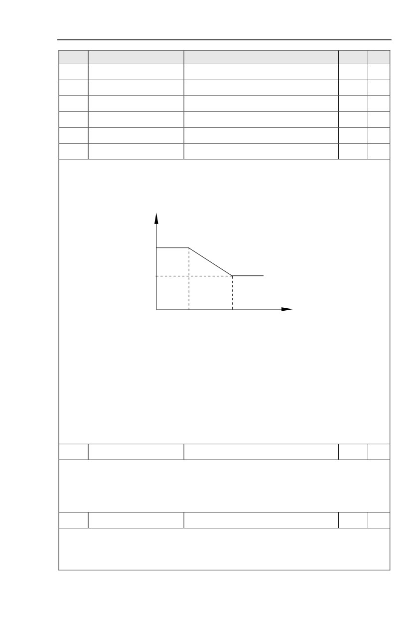
Users could choose different speed loop PI parameters under different running frequency. When
running frequency is less than the switching frequency(P2.02), adjusting parameters for speed loop PI are
P2.00 and P2.01. When running frequency is greater than the switching frequency (P2.02), adjusting
parameters for speed loop PI are P2.03 and P2.04. Speed loop PI parameters between switching
frequency1 and switching frequency2 are two groups of linear switching. As shown in fig.5.2:
PI parameter
P2.00
P2.01
P2.03
P2.04
P2.02
P2.05
Frequency command
Fig.5-2PI parameter schematic diagram
Users can adjust vector control speed dynamic response characteristics through setting proportional
coefficient and integration time of the speed regulator.
Both increasing proportional gain and reducing integration time can accelerate the speed loop
dynamic response.But excessive proportional gain or insufficient integration time may led to system
oscillation.
Suggestions for regulating method:
If the factory parameters can not meet the requirements, users can fine-tuning it on the basis of factory
value parameters. First increase the proportional gain to restrain system oscillation,then
reduceintegrationtime so that system has fast response characteristic and smaller overshoot.
Notice:Improper PI parameter setting may lead to excessive speed overshoot , even voltage fault
during overshoot drop.
P2.06
Vector control slip gain
50%~200%
100%
☆
This parameter is used to adjust motor steady speed precision for zero-speed sensor vector control
mode. Please turn up the parameter value when with load motor running in low speed. On the contrary,
when the with load motor running in high speed, please turn down the parameter value.
This parameter is also used to adjust the output current value with the same load for speed sensor
vector control.
P2.07
Speed-loop filter time
0.000s~0.100s
0.000s
☆
In vector control mode, speed-loop regulator outputs torque current command. P2.07 is used to filter
the torque command.
Generally speaking, the parameter needs not to be modified. Users could properly increase the
filtering time when speed fluctuation is relatively big, and decrease the value when motor oscillation occurs.
63