HSD2000 Series Servo Drive. Operation Manual V1.2 - page 9

Chapter IX Functional Code List
LED Ones place: Start mode
0: Automatic
1: Terminal manual
LED Tens place: amplitude control
0: Relative center frequency
1: Relative max frequency
Traverse
Traverse operation
LED Hundreds place: traverse frequency
P30.01
operation running
1
0000
×
running mode
status memory
mode
0: Stop memory
1: Not stop memory
LED Thousands place: traverse frequency
status power off saved
0: Memory
1: No memory
Traverse
Traverse frequency
P30.02
frequency preset
0.00Hz~Upper frequency limit
0.01Hz
0.00Hz
○
preset frequency
frequency
Traverse frequency
Traverse
P30.03
preset frequency
frequency
0.0~3600.0s
0.1s
0.0s
○
waiting time
waiting time
Traverse
Traverse frequency
P30.04
frequency
0.0%~50.0%
0.1%
0.0%
○
amplitude value
amplitude value
P30.05
Hot frequency
Hot frequency
0.0%~50.0%
0.1%
0.0%
○
Traverse frequency
Traverse
P30.06
0.1~999.9s
0.1s
10.0s
○
period
frequency period
Triangular wave
0.0%~100.0%(means: Traverse frequency
P30.07
Rising time
0.1%
50.0%
○
rising time
period)
P97: Servo driver Parameters
Functio
Min
nal
Name
LCD DISPLAY
Setting Scope
Default
Change
Unit
Code
P97.00
Series No
Series No
0~FFFF
1
6000
Software version
Software version
P97.01
0.00~99.99
1
1.00
No.
No.
Customized
Customized
P97.02
0~9999
1
0
version No.
version No.
Setting by
Output power, 0~999.9kVA(Automatic
P97.03
Rated capacity
Rated capacity
0.1kVA
manufactu
setting by machine type)
rer
Setting by
P97.04
Rated voltage
rated voltage
0~999V(Automatic setting by machine type)
1V
manufactu
rer
Setting by
0~999.9A(Automatic setting by machine
P97.05
Rated current
rated current
0.1A
Manufact
type)
urer
P98: Customized Parameters Group
Functional
Min
Name
LCD DISPLAY
Setting Scope
Default
Change
Code
Unit
9999 No
Customized
Customized
P98.00~P98.31
P00.00~P99.99
1
customized
○
Parameters1~32
Parameters1~32
Parameters
160

Chapter IX Functional Code List
P99: Manufacturer Parameters
Functio
LCD
Min
nal
Name
Setting Scope
Default
Change
DISPLAY
Unit
Code
Password Input
****
Manufacturer’s
Setting by
P99.00
by
Note: After correct password input, the
1
-
password
manufacturer
manufacturer
parameters left in the group will be shown.
Note:
○: Change in working; ×: No change in working; *: Actual parameters, unable to change; -Manufacturer setting, unable to change by
users.
161
Appendix I: Communication Protocol
Appendix I: Communication Protocol
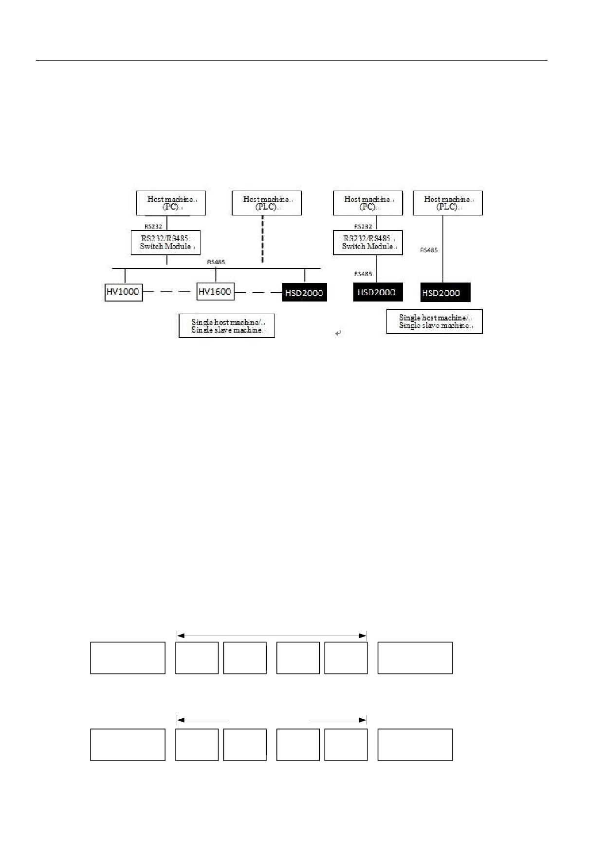
1. Networking mode
As given in Fig 1, the networking mode of servo drive has two kinds: single host machine/several slave machine, single
machine/single slave machine.
Fig. 1 Servo Driver Networking Diagram
2. Interface
RS485 interface: asynchronous, half-duplex. Default: 1-8-N-2, 9600bps, RTU. Parameters setting refers to group P18 Functional Code
Indication.
3. Communication
1.Based on the Modbus protocol, servo driver not only support common reading/writing of register but also extend some commands and
manage the servo driver functional codes.
2.Servo driver is a slave machine, master-slave point-point communication. When the host machine use broadcast address to send
commands, the slave machine will make no replies.
3.In case of several machine communications or long distance, connect at positive and negative terminals of main station communication
signal lines in parallel resistance of 100~120ohm to improve the communication immunity.
4.HSD2000 offers only RS485 interface, if the external comm.. interface is RS232, it will need additional RS232/RS485 switch devices.
4. Protocol format
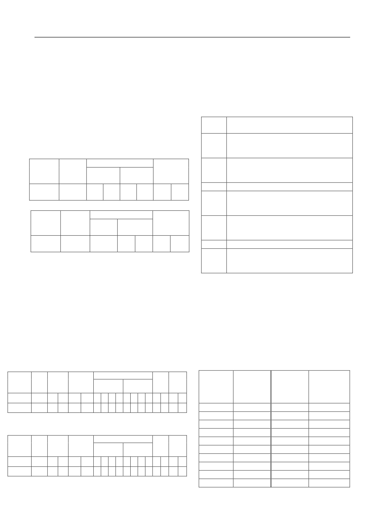
Modbus protocol supports RTU and ASCII, corresponding frame formats are given in Fig. 2.
RTU
Fig.
2 Modbus Protocol
Modbus data frame
Format
Initial (at least 3.5
Slave
Comman
Data
Check
End
(at
3.5
character free)
machine
d code
code
characters free)
Modbus
address
adopts
“Big Endian”
in coding,
firstly sending high bit,
followed
by low one.
ASCI
Modbus data frame
Initial (0x3A)
Slave
Comman
Data
Check
End
(0x0D,
machine
d code
code
postamble byte)
address
162
Appendix I: Communication Protocol
1.RTU
Through functional code, servo driver can set different response
time delay to meet different main stations, for RTU mode, the
Under RTU, free time between frames shall take the bigger value
response time delay shall keep at least 3.5 characters interval; for
between function code setting and Modbus value agreed internally.
ASCII mode, the response time delay shall be not less than 1ms.
The min frame agreed in Modbus shall be: the bus-through time
from frame head to frame end shall have at least 3.5 characters to
5.
Protocol function
define frames. Data check adopts CRC-16, all information will be
checked, check and high/low bit shall be exchanged for sending.
Modbus’ most function is to read/write parameters, different
Specific CRC check refers to samples attached hereto. Note: there
command codes decide different operation requests. HSD2000
shall be 3.5 characters at least for bus free between frames, and
servo driver Modbus protocol support the operation in the table.
the bus free between frames shall not need to accumulate initial
Command
Description
and final idle.
code
The following is applicable for: under RTU, read the register
Read servo driver parameters, including functional
0101(P01.01) parameters from No. 5 slave machine.
0x03
code parameters, control parameters and status
Request frame:
parameters
Slave
Data
Modify single 16-bit servo driver functional code
Comman
machine
Register
Read
Check code
0x06
parameter or control parameters, after power off,
d code
address
address
characters
servo driver keeps no parameters.
0x0
0x0
0x0
0x0
0xD
0xB
0x08
Line diagnosis
0x05
0x03
1
1
0
1
5
2
Modify several servo driver functional code or
0x10
control parameters, after power off, servo driver
Response frame:
keeps no parameters.
Slave
Data
Comman
Modify single 16-bit servo driver functional code
machine
Respons
Register
Check code
d code
0x41
parameter or control parameters, after power off,
address
e bit
content
servo driver keeps parameters.
0x1
0x8
0x4
0xD
0x05
0x03
0x02
0x42
Servo driver functional code management
3
8
4
2
Modify several servo driver functional code or
0x43
control parameters, after power off, servo driver
Where, check code is CRC check value, CRC check calculations
keeps parameters.
refer to the following instruction.
2.ASCII
Servo driver’s functional code parameters, control parameters and
Under ASCII, the frame head is “0x3A”, the frame end default:
status parameters all image to be Modbus’s read/write register.
“0x0D,0x0A”, which can be also set by users, under the mode,
except the frame head and the frame end, other data bytes all
Reading/writing characteristics and scope of functional code
adopt ASCII codes for sending, first sending high 4 byte, followed
parameters follow servo driver user manual. Group number of
by low one. Under ASCII, the data have 7 digits, for “A”~“F”,
servo driver functional code images to be high bit of register
adopt uppercase ASCII codes. At the time, the data adopt LRC for
address, index in groups (namely parameters’ number in the group)
check, which cover from slave machine address to data
images to be low bit of register address. Servo driver’s control
information. Total check equals to all characters for check and
parameters and status parameters are taken as servo driver
complement codes (no carry available).
functional code group. Functional code group number and its
The following is applicable for: under ASCII, write the register
imaged high bit of register address have coincidence relations as
0201(P02.01) parameters from No. 5 slave machine.
follows:
Request frame:
Slave
Data
Servo
Frame
Command
Check
Frame
High Bit of
Servo driver
machine
Register
Written
driver
High Bit of
Head
Code
code
End
Image
Group
address
address
Content
Group
Image Address
Address
Parameters
Character
:
0
5
0
6
0
2
0
1
0
F
A
0
4
3
CR
LF
Parameters
ASCII
3A
30
31
30
36
30
32
30
31
30
46
41
30
34
33
0D
0A
Group P00
0x00
Group P19
0x13
Where, Check code is total LRC check, equal to complement
Group P01
0x01
Group P20
0x14
codes of (05+06+02+01+0x0F+0xA0).
Group P02
0x02
Group P30
0x1E
Response frame:
Group P03
0x03
Group P31
0x1F
Slave
Data
Frame
Command
Check
Frame
Group P04
0x04
Group P32
0x20
machine
Register
Written
Head
Code
code
End
Group P05
0x05
Group P33
0x21
address
address
Content
Group P06
0x06
Group P34
0x22
Character
:
0
5
0
6
0
2
0
1
0
F
A
0
4
3
CR
LF
Group P07
0x07
Group P35
0x23
ASCII
3A
30
31
30
36
30
32
30
31
30
46
41
30
34
33
0D
0A
Group P08
0x08
Group P36
0x24
Group P09
0x09
Group P40
0x28
163

Appendix I: Communication Protocol
Servo
Abnormality code
1
High Bit of
Servo driver
driver
High Bit of
Abnormality code and meaning given as follows:
Image
Group
Group
Image Address
Abnormality
Address
Parameters
Parameters
Description
code
Group P10
0x0A
Reserved
Reserved
0x01
Illegal command code。
Group P11
0x0B
Reserved
Reserved
0x02
Illegal register address。
Group P12
0x0C
Reserved
Reserved
Data error (data are out of upper/lower limit
Group P13
0x0D
Reserved
Reserved
0x03
scope)
Group P14
0x0E
Group P97
0x61
Operation on slave machine fails, including data
Group P15
0x0F
Group P98
0x62
0x04
within upper/lower limit scope, but the invalid
Group P16
0x10
Group P99
0x63
data cause errors.
Control
Valid command in process, main applications are
Group P17
0x11
Parameters
0x32
0x05
in memory data to non-volatile memory.
Group
The slave machine is occupied, please wait, main
Status
0x06
applications are in memory data to non-volatile
Group P18
0x12
Parameters
0x33
memory.
Group
Operation not supported (mainly for control
0x16
parameters and status parameter, as ort attribute,
For example, servo driver functional code parameters P03.02’s
reading of upper/low limit of default.
register address is 0x0302, the first control parameters( control
Register quantity error in request frame(as Bit is
command 1)’s register address is 0x3200。
0x17
odd number for 32btye operation)
Whole data frame format have been given as above, the following
Info frame error: Including info length error and
will specify Modbus protocol
“Command Code” and “Data”
0x18
check error
formats and meaning. The two parts form Modbus’s application
0x20
Parameters unable to change
layer protocol data unit as given below. The following frame
0x21
Servo driver works, parameters unable to change
format is based on RTU mode, ASCII mode application layer
0x22
Parameters under password protection
protocol data unit will be doubled in length.
1.Read servo driver parameters
2.Modify single 16-bit servo driver functional code parameter
Application layer protocol data unit given as follows:
and status parameters, after power off, servo driver keeps no
Request format:
parameters.
Application layer
During the command operation, after power off of servo driver,
Data Length(Bit)
Value or Scope
protocol data unit
with power supply the parameters will keep unchanged.
Command code
1
0x03
Application layer protocol data unit given as follows
Initial register
Request format:
2
0x0000~0xFFFF
address
Application layer
Data Length(Bit)
Value or Scope
Register quantity
2
0x0001~0x000A
protocol data unit
Response format for successful operation:
Command code
1
0x06
Application layer
Register address
2
0x0000~0xFFFF
Data Length(Bit)
Value or Scope
protocol data unit
Register content
2
0x0000~0xFFFF
Command code
1
0x03
2×register
Response format for successful operation:
Read bit
1
quantity
Application layer
Data Length(Bit)
Value or Scope
Parameter
protocol data unit
Read content
2×register quantity
value
Command code
1
0x06
If the operation fails, it will return abnormal response frame,
Register address
2
0x0000~0xFFFF
including error code and abnormal code, where error code =
Register content
2
0x0000~0xFFFF
(Command code+0x80), and abnormal code will show reasons
If the operation fails, it will return abnormal response frame given
for errors.
as above.
Abnormal response format:
3.Line diagnosis
Application layer
Application layer protocol data unit given as follows
Data Length(Bit)
Value or Scope
protocol data unit
Request format:
(Command code
Error code
1
Application layer
Data Length(Bit)
Value or Scope
+0x80)
164

Appendix I: Communication Protocol
protocol data unit
Sub-Command
Data(Request)
Data(Response)
Meaning
Command code
1
0x08
code
Sub-command code
2
0x0000~0x0030
Set “No response
Data
2
0x0000~0xFFFF
mode”, under
which, the slave
Response format for successful operation:
machine only
responds
Application layer
Data Length(Bit)
Value or Scope
protocol data unit
“Re-initializing
communication
Command code
1
0x08
request” (request
Sub-command code
2
0x0000~0x0030
0x0004
0x0000
No response
of sub-function
Data
2
0x0000~0xFFFF
code 0x0001) and
If the operation fails, it will return abnormal response frame given
nothing to other
as above.
requests. The
Command code supported by line diagnosis and meaning are
function is mainly
given as follows:
used for slave
Sub-Command
Data(Request)
Data(Response)
Meaning
machines failing
code
and separated.
Re-initializing
Set “Slave
communication:
machine makes
0x0000
0x0000
make “No
no responses”
response mode”
0x0000
0x0000
invalid command
invalid
and error
0x0001
Re-initializing
0x0030
command。
communication:
Set “Slave
0xFF00
0xFF00
make “No
machine response
response mode”
0x0001
0x0001
invalid”
invalid
command and
Set the frame end
error command。
of ASCII mode to
4.During the command operation, after power off of servo driver,
replace the
with power supply the parameters will keep unchanged.
original line break
symbol, in case of
Application layer protocol data unit given as follows:
High bit
power off, the
Request format:
High bit is“new
is“new frame
new frame end
Application layer
0x0003
frame end”,
Data Length(Bit)
Value or Scope
end”, low bit
will keep no
protocol data unit
low bit is “00”
is “00”
change. (Note:
Command code
1
0x10
the new frame
Initial register
2
0x0000~0xFFFF
end shall not
address
exceed 0x7F and
Operating register
2
0x0001~0x000A
not equal to
quantity
0x3A).
Register content
2×Operating
1
Byte
register quantity
2×Operating register
Register content
quantity
Response format for successful operation:
Application layer
Data Length(Bit)
Value or Scope
protocol data unit
Command code
1
0x10
Initial register
2
0x0000~0xFFFF
address
Operating register
2
0x0001~0x000A
quantity
165

Appendix I: Communication Protocol
The command is used to modify contents of continuous data unit
Sub-command
Data(Request)
Data(Response)
Meaning
starting from the register address.
code
If the operation fails, it will return abnormal response frame given
bits
parameters)
as above.
respectively
Parameter
5.Modify single 16-bit servo driver functional code parameter
Read
group number
and status parameters, after power off, servo driver keeps
Parameters’
parameters’
and group
parameters.
lower
lower limit
0x0001
index occupy
Command code 0x41 is used to modify single 16-bit servo driver
limit(4-bit
(Not supported
high and low
functional code parameters or control parameters, and save in
length)
by status
bits
non-volatile memory unit.
parameters)
respectively
The command format is the same as that of 0x06, and the sole
Read
difference is: 0x06 Command operation parameters, after power
Parameter
functional code
off, keeps no parameters, and 0x41 operation parameters, after
group number
Parameter
parameters’
power off, keeps parameters.
and group
characteristics
characteristics
6.Servo driver functional code management
0x0002
index occupy
(refer to
(Not supported
Servo driver functional code management include reading
high and low
character table
by control
upper/lower limit of parameters, parameters characteristics,
bits
for details)
parameters and
functional code menu max index in group, read the next functional
respectively
status
code group number and previous functional code group number,
parameters)
read current parameter display index, display the next status
Parameter
Read the
parameters, read the default of functional code parameters.
group number
Quantity of
quantity of
Parameters characteristics include parameters’ readability and
0x0003
occupies high
parameters in
parameters in
writability, parameter unit and calibration relation. The commands
bit, the low
the group
the group
are used for remote modification. Servo driver Functional Code
bit is “00”
Parameters。
Parameter
High bit is the
Read the
Application layer protocol data unit given as follows
group number
next group
number of next
Request format:
0x0004
occupies high
number of
parameter
bit, the low
parameters, low
Application layer
group
Data Length(Bit)
Value or Scope
bit is “00”
bit is “00”
protocol data unit
Parameter
High bit is the
Read the
Command code
1
0x42
group number
next group
number of
Sub-Command code
2
0x0000~0x0008
0x0005
occupies high
number of
previous
Decided by servo
Data
2
bit, the low
parameters, low
parameter
driver type
bit is “00”
bit is “00”
group
Response format for successful operation:
Read current
display of
Application layer
Data Length(Bit)
Value or Scope
status
protocol data unit
parameter
Command code
1
0x42
Current display
index (Status
Sub-Command code
2
0x0000~0x0008
of status
0x0006
0x3300
parameters’
0x00000000~
parameters
Data
2 or 4
meaning is
0xFFFFFFFF
index
defined in the
If the operation request fails, the response shall be error code and
status
abnormality code, and the abnormality response codes can refer to
parameter
the description mentioned above.
group)
Functional code manages and supports sub-command code as
Display the
follows:
next status
Sub-command
parameters
Data(Request)
Data(Response)
Meaning
code
Next status
(Status
Parameter
Read
0x0007
0x3300
parameters
parameters’
Parameters’
group number
parameters’
index
meaning is
upper
0x0000
and group
upper limit
defined in the
limit(4-bit
index occupy
(Not supported
status
length)
high and low
by status
parameter
166

Appendix I: Communication Protocol
Sub-command
Bit
Characteristic
Value
Meaning
Data(Request)
Data(Response)
Meaning
code
Restore to
1
Restore
BIT10
group)
Default
0
Not restore
Read the
1
Valid
BIT11
Quick menu
Parameter
default of
0
Invalid
group number
functional code
1
Valid
BIT12
Basic menu
and group
parameters(Not
0
Invalid
Parameters’
0x0008
index occupy
supported by
16/32-bit
1
32 位
Default
high and low
control
BIT13
Parameters
0
16 位
bits
parameters and
BIT15~BIT14
Reserved
respectively
status
parameters)
7.Modify several servo driver functional code parameters and
status parameters, after power off, servo driver keeps parameters.
In the table, when read the upper/low limit of parameters, the data
length returned shall be 32-bit length, namely four bytes. The
Command code 0x43 is used to modify several servo driver
functional code parameters or control parameters, and save in
operation is not supported by status parameters. The upper/low
non-volatile memory unit.
limit read in the operation shall be that to be reached by the
functional code parameters, if the parameters’ scope is limited by
The command format is the same as that of 0x10, and the sole
other functional code parameters (namely related to the functional
difference is: 0x10 Command operation parameters, after power
code parameters), it shall consider the related functional code
off, keeps no parameters, and 0x43 operation parameters, after
parameters for decision.
power off, keeps parameters.
Except otherwise stated, the data length of response frame shall
6.
Servo driver’s control parameters and status
have 2 bits.
parameters
Functional code parameters’ characteristics have two-bit length,
Servo driver’s control parameters can servo driver startup, stop,
which is defined as follows:
setting work frequency and so on. Searching the servo driver’s
Bit
Characteristic
Value
Meaning
status parameters to obtain servo driver’s work frequency, output
Decimal system
Upper limit
0
current, output torque and other parameters.
BIT0
restriction
restriction
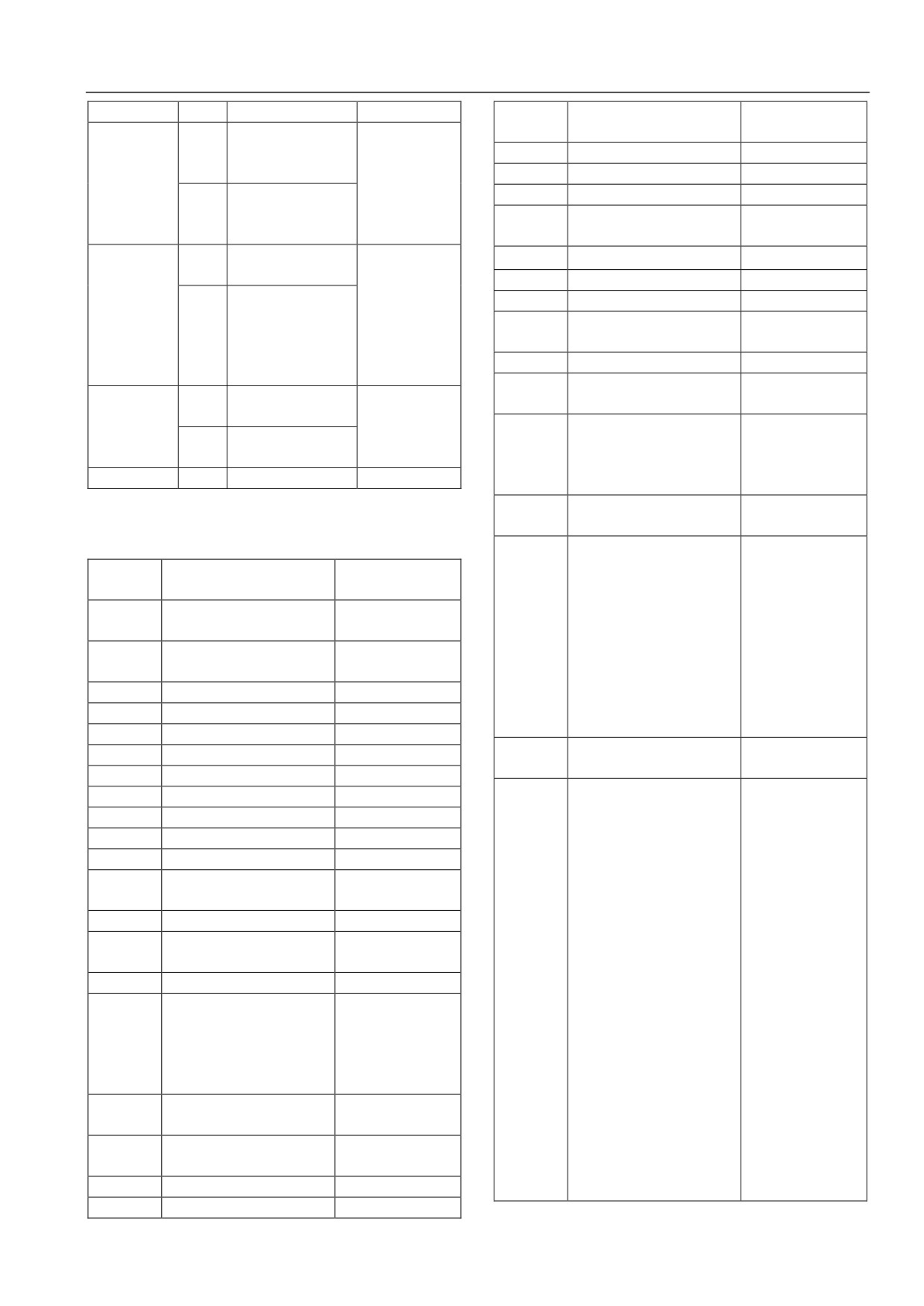
1.Control parameters
1
Hex restriction
000B
Part without decimals
Servo driver’s control parameters given as follows:
001B
1 decimal
Save
Regist
010B
2 decimals
in
Decimal
er
Parameters
BIT3~BIT1
011B
3 decimals
Pow
Remark
Position
addres
Name
100B
Step size: 2
er
s
101B
Step size: other
Off
0x320
Control
Refer to the definition
Other
Reserved
No
0
command1
table
Real parameters,
00B
Main given frequency;
unable to change
valid for main given
01B
Change in working
0x320
channel as serial comm.;
Modify
No change/factory
Main given
No
BIT5~BIT4
1
whether or not to save
attributes
setting in working,
10B
shall relate to P14.06
unable to change by
setting
users
0x320
work frequency
11B
Reserved
No
As above
2
given
000B
No unit
0x320
Digit Process
Process close-loop
001B
Unit: Hz
Yes
3
close-loop given
enabled
010B
Unit: A
0x320
Pulse Process
011B
Unit: V
HSD2000: not supported
BIT8~BIT6
Display unit
4
close-loop given
100B
Unit: r/min
0x320
analog outputAO1
P11.17=14: Valid
101B
Unit: line speed(m/s)
No
5
setting
110B
Unit: percent(%)
0x320
analog outputAO2
P11.21=14: Valid
Other
Reserved
No
6
setting
BIT9
Reserved
0x320
Digit output DO
No
P10.32=17: Valid
167

Appendix I: Communication Protocol
Save
Valu
Regist
Bit
Function
Remark
in
e
er
Parameters
Pow
Remark
101
addres
Name
Mode 1: stop
Free to stop
er
B
s
Off
Free to stop, servo
100
Stop due to external
7
setting
driver displays
B
fault
0x320
frequency ratio
external fault
HSD2000: not supported
8
setting
011
HSD2000: not
Mode 2: stop
BIT0~BIT9:
B
support
X1~X8/FWD/REV, valid
Othe
No command
for bits in P10.17;
r
0x320
Virtual Terminal
No
BIT10~BIT13:
1
Reverse
Set work direction with
9
control setting
BIT3
Y1/Y2/RO1/RO2,
0
Forward
work command valid
P10.18~P10.21=17
1
Jog Forward
Jog does not act with
BIT4
Terminal: Valid
0
Jog Forward invalid
normal and reverse
0x320
Setting acceleration
1
Jog Reverse
valid, and stops with
Yes
A
time1
BIT5
normal and reverse
0
Jog Reverse invalid
0x320
Setting
invalid
Yes
B
Deceleration time 1
Allow
Auxiliary given channel:
1
accelerating/Decele
When the bit is valid,
0x320
Auxiliary
serial comm, Auxiliary
ration
the control 1’s
No
BIT6
C
frequency given
given bits( Control 2’s
Disable
BIT5~BIT0 will be
BIT2): valid
0
accelerating/Decele
valid
Torque control mode,
ration
0x320
torque given channel:
Upper computer
Torque given
No
1
Valid option bit of
D
serial and under torque
control 1 valid
BIT7
control 1 of upper
control mode: valid
Upper computer
0
computer
Torque control mode:
control 1 invalid
Torque given channel:
1
Reserved
0x320
Torque current
BIT8
Reserved
No
serial and under torque
0
Reserved
E
given
current control mode:
1
Fault reset valid
Valid option bit for
valid
BIT9
upper computer fault
0
Fault reset invalid
0x321
Control command
Refer to the definition
reset
No
2
2
table
BIT15
0000
~BIT1
Reserved
00B
Attentions
0
1.When reading control parameters, the return value will be the
one written in previous communication;
Attentions
2 . Within control parameters, max length of
“Main
1.Upper computer’s control command(control command 1 and
setting”,“ work frequency setting” and
“Auxiliary frequency
control command 2) shall be valid with “Work command channel
setting” shall be 32 bits, and others shall be 16 bits in length;
option” value equal to “Communication Command” ; When the
3. Within control parameters, all units given, input/output setting
control 1’s BIT7 bit is valid, the whole control 1 will be valid;
When control 1’s BIT6 bit is valid, BIT5~BIT0 will be valid.
scope, decimal calibration and so on can be seen in related
functional code parameters。
2.Upper computer’s treatment on fault and alarm: When servo
driver fails, as for control 1 and 2 command, except the fault reset
Control command 1 is defined as follows:
command, the upper computer will be invalid if sending other
Valu
commands. Namely the upper computer shall firstly reset the fault
Bit
Function
Remark
e
before sending command. When alarms exist, the control will be
valid.
Start servo driver
111
Control Command 2 is defined as follows:
Work Command
(Valid when JOG is
B
invalid)
Bit
Value
Function
Remark
BIT2~
Stop as per the set
Servo driver work
BIT0
1
Servo driver
110
deceleration
disable
Mode 0: stop
BIT0
allow/disable
B
time(Valid when
Servo driver work
0
work option bit
JOG is invalid)
allowed
168
Appendix I: Communication Protocol
Bit
Value
Function
Remark
Register
Parameters Name
Remark
Work( direction
address
1
taken from
0x3314
The 3rd (latest) work fault
functional code)
0x3315
work frequency setting
BIT1
Work direction
Other work
0x3316
Setting rotation speed
0
status(refer to
Analog Process close-loop
0x3317
control 1)
setting
Auxiliary given
Valid option
0x3318
setting 线 Speed
1
valid
bit for
0x3319
AI1
Auxiliary
0x331A
AI2
BIT2
given
HSD2000: not
Auxiliary given
0
frequency of
0x331B
Setting length
support
invalid
upper
0x331C
Setting acceleration time1
computer
Setting Deceleration time
Upper computer
Valid option
0x331D
1
1
control 2 valid
bit for control
BIT3
Command given channel:
Upper computer
2 of upper
0
0: Panel control;
control 2 invalid
computer
0x331E
1: Terminal control;
BIT15~BIT4
Reserved
2: Serial port control
Note: When control command’s BIT3 bit is
valid, the whole
Servo driver operating
0x331F
control 2 will be valid.
status 2
2.Status parameters
frequency given
Register
channel:
Parameters Name
Remark
address
0: Digit given1(operation
panel▲▼ given);
Servo driver operating
0x3300
status 1
1: Digit given2(Terminal
0x3320
UP/DOWN given);
Current main given actual
Current work
0x3301
2: Digit given3(Serial
work value
frequency
port);
0x3302
Slave machine type
3: AI analog given;
0x3303
Servo driver type
4: Terminal PULSE given;
0x3304
Software version
HSD2000: not
0x3305
Current work frequency
0x3321
Accumulated length
support
0x3306
Output current
Motor and mode option:
0x3307
Output voltage
Ones place: Motor 1
0x3308
Output power
control mode option
0x3309
Work rotation speed
0: Vector control without
0x330A
Work line speed
PG
Analog Process close-loop
0x330B
1: Vector control with PG
feedback
2: V/F control without PG
0x330C
Bus voltage
3: V/F control with PG
HSD2000: not
0x330D
External counter
Tens place: Motor 1 type
support
option
0x330E
Output torque
0x3322
0: Asynchronous motor
BIT0~BIT9:
1: Synchronous motor
X1~X8/FWD/REV
Switch Input output
Hundreds place: Motor 2
0x330F
;
terminal status
control mode option
BIT10~BIT13:
0: Vector control without
Y1/Y2/RO1/RO2
PG
HSD2000: not
1: Vector control with PG
0x3310
Actual length
support
2: V/F control without PG
Work frequency after
HSD2000: not
3: V/F control with PG
0x3311
compensation
support
Thousands place: Motor 2
0x3312
The 1st work fault
type option
0x3313
The 2nd work fault
169

Appendix I: Communication Protocol
Register
Bit
Value
Function
Remark
Parameters Name
Remark
address
0: Servo driver is
0: Asynchronous motor
normal;
1: Synchronous motor
Non 0: fault/alarm,
0x3323
Bus voltage at the 3rd fault
specific fault/alarm
BIT15~B
0x00~
Fault/alarm
Actual current at the 3rd
codes can be seen in
0x3324
IT8
0xFF
code
fault
user manual.
Work frequency at the 3rd
Fault/alarm can be
0x3325
fault
seen in status 1 defined
Servo driver operating
Bit is defined as
in BIT7.
0x3326
status at the 3rd fault
work status 1
Servo driver operating status 2 is defined as follows:
0x3327
AI3
Servo driver operating
Bit
Value
Function
Remark
0x3328
status 3
1
Jog Work
BIT0
0
Non-Jog Work
Process close-loop
Attentions
1
Work
1.Status parameters do not support writing operation.
BIT1
Non Process
2.Within status parameters, max length of “Actual work value of
0
close-loop Work
main setting”,“ work frequency setting” and “work frequency at
1
PLCWork
the 3rd fault” shall be 32 bits, and others shall be 16 bits in length.
BIT2
0
Non-PLC Work
Servo driver operating status 1 is defined as follows:
Multiplex
Bit
Value
Function
Remark
1
frequency Work
Servo driver
BIT3
1
Non-Multiplex
Work
0
BIT0
frequency Work
Servo driver
0
1
Common Work
Stop
BIT4
0
Uncommon Work
Servo driver
1
Traverse
Reverse
1
BIT1
frequency
Servo driver
BIT5
0
Non-Traverse
Forward
0
frequency
Reach main
1
1
Under voltage
setting
BIT6
BIT2
0
Normal voltage
Fail to reach
0
BIT7
Reserved
main setting
BIT8
Servo Work
Allow serial
1
BIT9
Customized Work
port control
BIT3
Synchronous
Disable serial
BIT10
0
speed work
port control
Other
Reserved
Allow serial
1
port given
BIT4
Servo driver operating status 3 is defined as follows:
Disable serial
0
Bit
Value
Function
Remark
port given
BIT0~BIT1
Reserved
BIT5~BI
Reserved
BIT2
Zero-speed Work
T6
BIT3
Accelerating
When the bit is 0, it
1
Alarm
BIT4
Decelerating
shall consider control
Constant-speed
1’s BIT15~8 to judge
BIT5
Work
whether it is normal or
BIT7
BIT6
Pre-excitation
Fault or
fault. BIT15~8 equal to
0
normal
0 means normal,
BIT7
Setting
otherwise, it will be
Over current
BIT8
fault.
limit
DC over voltage
BIT9
limit
170

Appendix I: Communication Protocol
Bit
Value
Function
Remark
16 bits
32 bits
BIT10
Torque limit
Slave machine
0
0x05
0x05
BIT11
Speed limit
address
BIT12
Servo driver fails
1
0x03
0x03
Command code
BIT13
Speed control
2
0x08
0x10
Read bit
BIT14
Torque control
P01.01
3~4
BIT15
Position control
value
P01.01 value
7.
Expansion access
P01.02
5~6
value
Read content:
Standard Modbus protocol support 16-bit register, the description
P01.03
16-bit: 8 bits
mentioned above are based on 16-bit registers. HSD2000 serial
7~8
value
servo driver’s parameters include 16-bit (single character) and
P01.02 value
P01.04
32-bit length, so the parameter reading/writing operation shall
9~10
value
consider the data of two length.
Check
The access to servo driver parameters has 16 bit and 32 bit,
11~12
code
P01.03 value
namely take 16 bits and 32 bits as unit for read/write parameters
32-bit mode: total
13~14
-
respectively. Use “initial register address” in request frame to
16 bytes
differentiate the access of 16 bits and 32 bits, if the max bit of the
15~16
-
P01.04 value
address is “0”, just read/write as per 16 bits, otherwise, do as per
17~18
-
32 bits as follows.
19~20
-
Check code
Initial register address
Access
If the operation fails, it will return abnormal response frame as
Remark
BIT15
BIT14~BIT0
Type
given above.
Actual address of initial
Servo driver parameters have two kinds: the first kind takes
0
16 bits
parameters
decimal system restriction to indicate parameters of real variables;
Actual address of initial
the second kind takes hex restriction. The first one is used for real
1
32 bits
parameters
variable such as current, voltage
, frequency
, power, torque,
percent and so on, negative or positive, the data type is int or long;
When accessing to parameters as per 32 bits, for the register in the
the second one is used for mode option or status indication such as
request frame takes 16 bits as unit, each 32 bit parameter needs to
parameters option, work status, no negative or positive, and the
use two
16-bit registers, so it needs to set correct
“register
data type is unsigned int and unsigned long. Parameters’ type and
quantity”. The “register quantity” in the request frame is two
value scope are given in the following:
times of parameters to be accessed, otherwise, it will return
Type
Bit Qty
Value Scope
Remark
abnormal response frame.
int
16
-32768~32767
1.Read operation
Category I
-
long
32
Parameters
16-bit access is the same as what given above, as for the 32 bit
2147483648~2147483647
access, the returned data take 32 bits as unit, as given below, read
unsigned
four continuous Functional Code(Slave machine address: ) with
16
0~65535
int
Category II
P01.01 as initial address.
unsigned
Parameters
Request frame:
32
0~4294967296
long
Value
Bit
Description
16 bits
32 bits
If a 16-bit access is used to read parameters of 32-bit in length, it
0
0x05
0x05
Slave machine address
will return with the low 16 bits of 32-bit parameters taken, the
1
0x03
0x03
Command code
value take may be not equal to the real value, which will be
Initial address (for 32 bits, the
explained in the context.
2~3
0x0101
0x8101
highest level of initial
If 32-bit operation is used to read 16-bit parameter in length, it
address is1)
will return an extended 32-bit data, namely the 16-bit parameter
Register quantity(for 32 bits,
value is extended. Principle for length extending: if the highest bit
4~5
0x0004
0x0008
register quantity is twice of
of the 16-bit parameter is 0, 0 will be added to the highest 16th bit;
parameter quantity)
if the highest bit of the 16-bit parameter is 1, it will need to judge
Check
Check
the parameter category, if it belongs to category I, 1 will be added
6~7
CRC check
code
code
to the highest 16 bit; if it belongs to category II, 0 will be added to
the highest 16 bit.
Response frame after successful operation:
With the same data length, namely read 16-bit parameters under
Bit
Value
Description
16 bit mode, read 32-bit parameters under 32 bit mode, it needs no
171

Appendix I: Communication Protocol
length extension or take, and return original data directly. For
initial register address in the request frame is 1, it will return
example:
abnormal info frame and show address error.
P01.01 value:4500(16bits category I Parameters, 0x1194);
Attentions:
P01.02 value:65036(32bits category I Parameters, 0x0000FE0C);
(1) 16-bit write operation is applicable for category I parameter in
the scope of
-32768~32767 and category II parameters of
P01.03 value:-500(16bits category I Parameters, 0xFE0C);
0~0xFFFF.
P01.04 value:5000(32bits category I Parameters, 0x00001388);
(2) For category I parameters, when using the two commands to
P01.05 value
: 100000(32bits category I Parameters,
write 16-bit long value to 32-bit long parameters, the real value
0x000186A0);
will be extended one. Principle for length extension: extend as per
P01.06 value : -100000(32bits category I Parameters,
0x
the highest bit of 16-bit parameters, if the highest bit is 1, add
FFFE7960);
0xFFFF to the high 16 bit, otherwise, add 0x0000. If the extended
data are within upper/lower limit of parameters, the value is valid
P01.07 value:0x FFFF(16bit category II Parameters).
and parameters are allowed to modify, it can be written. Category
After read operation, the data return is given as follows:
II parameters will need no extension.
Register
Access
Returned
Description
For example: suppose Functional Code P01.01 and P01.02 are
address
Mode
Value
32-bit data and 16-bit data, both belong to category I parameters,
16 bits
0x1194
Return real value
P01.01
0 added to highest 16th bit,
if the write operation succeeds, the written data are given as
32 bits
0x00001194
Return real value
follows:
Take the lower 16th bit,
Value to
Register
Real Value
return value: -500,
be
Description
16 bits
0xFE0C
address
Written
P01.02
incompatible with real
Written
value
Add 0x0000 to high 16
0x1194
0x00001194
32 bits
0x0000FE0C
Return real value
bits
P01.01
16 bits
0xFE0C
Return real value
Add 0xFFFF to high
0xFE0C
0xFFFFFE0C
P01.03
1 added to highest 16th bit,,
16 bits
32 bits
0xFFFFFE0C
Return real value
0x1194
0x1194
P01.02
Take the lower 16th bit,
0xFE0C
0xFE0C
16 bits
0x1388
P01.04
Return real value
(2)Command code 0x10 and 0x43
32 bits
0x00001388
Return real value
The two command codes are used to modify servo driver
Take the lower 16th bit,
functional code parameters or control parameters, supporting
return value: -31072,
16 bits
0x86A0
16-bit and 32-bit access.
P01.05
incompatible with real
The 16-bit access is given as above.
value
As for the 32-bit access, the data to be written shall be 32-bit long.
32 bits
0x000186A0
Return real value
As given below, modify four continuous functional code (Slave
Take the lower 16th bit,
machine address: 5) with P02.00 as initial address.
return value: -31072,
16 bits
0x 7960
Request frame:
P01.06
incompatible with real
value
Value
Byte
Description
32 bits
0x FFFE7960
Return real value
16bits
32 bits
16 bits
0x FFFF
0
0x05
0x05
Slave machine address
Category II parameters, 0
0x10/0x4
0x10/0x4
P01.07
1
Command code
32 bits
0x0000FFFF
added to the highest 16th
3
3
bit
Initial address (for 32 bits,
In the above table, when 16-bit access is used to read 32-bit
2~3
0x0200
0x8200
the highest initial address
is 1)
parameters in length, it cannot assure that the return value will be
real parameters.
Register quantity(for 32
bits, register quantity is
So, more attention shall be paid to: under
16-bit mode, read
4~5
0x0004
0x0008
twice of parameter
operation is applicable for parameters of -32768~32767 only, and
quantity)
32 bits shall be needed for read operation of other parameters.
6
0x08
0x10
Register content Byte
2.Write operation
P02.00
P02.00
Content to be written:
(1) Command code 0x06 and 0x41
7~8
value
value
16-bit operation, total 8
The two command codes only support to change single 16-bit
long parameters but not support 32-bit access. If the highest bit of
172

Appendix I: Communication Protocol
Value
8.
Precautions
Byte
Description
16bits
32 bits
1.For command code 0x10 and 0x43, when write servo driver
P02.01
bytes
9~10
functional code parameters continuously, if the write operation of
value
any functional code is invalid (as invalid parameter, unable to
P02.02
11~12
modify parameters), it will return error and all parameters will not
value
P02.01
be modified; when write control parameters continuously, if the
P02.08
value
13~14
write operation of any parameter is invalid (as invalid parameter,
value
unable to modify parameters), the operation will return from the
Check
15~16
P02.02
first fault memory address, the parameter and followed ones
code
cannot be modified, but the previous ones can be written normally,
value
32-bit operation: total 16
17~18
-
and return error information.
bytes
19~20
-
P02.08
2. For some special functional codes, 0x06 and 0x41, 0x10 and
21~22
-
value
0x43 own the same function, during the write operation, keep
Check
power supply after power off to save parameters. Functional codes
23~24
-
code
are given in the following:
Functional Code
Description
Response frame after successful operation:
P00.03
Parameters protection setting
Value
P02.01
Motor option
Byte
Description
16-bit
32-bit
P10.00~P10.07
Input Terminal X1~X8 function option
0
0x05
0x05
Slave machine address
P14.06
Main setting frequency control
1
0x10/0x43
0x10/0x43
Command code
P14.07
Auxiliary frequency control
Initial address (for 32 bits,
P15.00
PLCWork mode
2~3
0x0200
0x8200
the highest initial address is
P30.01
Traverse frequency Work
1)
P03.00
Asynchronous motor1 rated power
Register quantity(for 32
P04.00
Asynchronous motor2 rated power
bits, register quantity is
P03.13
Synchronous motor1 rated power
4~5
0x0004
0x0008
twice of parameter
P04.13
Synchronous motor2 rated power
quantity)
P03.17
Synchronous motor1 pole number
Check
Check
P04.17
Synchronous motor2 pole number
6~7
CRC check
code
code
P03.18
Synchronous motor1rated rotation speed
If the operation fails, it will return abnormal response frame as
P04.18
Synchronous motor2rated rotation speed
given above.
Machine type setting(factory
P99.01
Attention:
Parameters)
(1) The
16-bit write operation is applicable for category I
Servo driver series option(factory
P99.09
parameters in the scope of -32768~32767 only, and category II
parameters)
parameters of 0~0xFFFF, and 32 bits shall be needed for write
3. Some control parameters cannot be saved in nonvolatile
operation of other parameters.
memory units, so as for such parameters, command code 0x41 and
(2) (2) For category I parameters, when using 16-bit access to
0x06, 0x43 and 0x10 own the same operation effect, namely
write 16-bit long value to 32-bit long parameters, the real value
during the write operation, keep power supply after power off and
written will be the extended one. Principle for length extension:
save no parameters. Refer to control parameters for details.
extend as per the highest bit of 16-bit parameters, if the highest bit
4. 6000Servo driver has some parameter reversed inside, which
is 1, add 0xFFFF to the high 16 bit, otherwise, add 0x0000. If the
cannot be modified through communication setting, such
extended data are within upper/lower limit of parameters, the
parameters are given as follows:
value is valid and parameters are allowed to modify, it can be
written. Category II parameters will need no extension and have
nothing to do with high 16 bits.
Functional Code
Function Description
(3) As for 32-bit access, whether the length of real parameters are
P00.00
Menu mode option
16 bits or
32bits, as long as the
32- bit value is within the
P00.05
Parameters copy
upper/lower limit, the value is valid and the parameter is allowed
Asynchronous motor1 Parameters self
to modify, it can be written successfully.
P03.11
setting
(4) If 16-bit access is used to modify 16-bit long parameters, just
Asynchronous motor2 Parameters self
refer to the contents concerned above.
P04.11
setting
P03.23
Synchronous motor1 position identified
173
Appendix I: Communication Protocol
P04.23
Synchronous motor2 position identified
5.Upper computer’s operation on user password and factory
password
(1) User password
1) Reading/writing of functional code parameters protected by
user password, functional code management (“read and display
data address”, except data switch display).
2) If user password is set
(P00.02!= 0), only after passport
removal, can the upper computer access to functional code
parameters, yet the access to control parameters and status
parameters will not be limited by password.
3) Upper computer cannot set, modify or cancel user password,
which can be done only through operation panel. As for P00.02
write operation, it is valid under two conditions only: I, remove
password if any; II, write 0 if there is no password, and invalid
operation return for other conditions.
4)Upper computer and operation panel have independent
operation on password, even the password is removed through the
operation panel, but the upper computer must have password
removed so as to access to functional code parameters through the
upper computer, vice versa.
5)After the upper computer obtains the right to access to
parameters, it will read the user password and return “0000” but
not the real user password.
6) After removal password, the upper computer will obtain the
right to access to functional code, if there is no communication
within 5 minutes, the access will be invalid. If it needs to access to
the functional code, just input password again.
7) After the upper computer obtains the right to access (no user
password or password removal), through the operation panel, set
the user password or new password, and the upper computer still
has the right to current access, needing no password removal
again. If failing to access, just remove the password (write new
password) to obtain the right to access.
(2) Factory password
1) Reading/writing of group P99 parameter for factory password
protection, functional code management of parameters in group
P99.
2) Only after password removal (write correct factory password to
P99.00), can the upper computer access to functional code of the
group P99; if there is no communication within 5 minutes with the
right to access, the right will be invalid automatically, and correct
password shall be input again to access to the group 99.
3)With the right to access to group P99, the upper computer will
read P99.00 and return “0000” but not real factory password.
4)Upper computer and operation panel have independent
password operation, namely correct password shall be input
respectively to access;
5)Upper computer has no right to modify the factory password,
when the upper computer write P99.00, the password must be
correct, otherwise, it will return invalid operation with prompt
“unable to modify”.
174
Appendix I: Communication Protocol
9.
CRC Check
In order to increase the speed, CRC-16 is expressed generally by form, the following are language C source code to realize
CRC-16, attention: the final result has exchanged high and low bytes and the result is the CRC total of CRC.
unsigned short CRC16 (unsigned char *msg, unsigned char length)
/* The function returns the CRC as a unsigned
short type */
{
unsigned char uchCRCHi = 0xFF ;
/* high byte of CRC initialized */
unsigned char uchCRCLo = 0xFF ;
/* low byte of CRC initialized */
unsigned uIndex ;
/* index into CRC lookup table */
while (length--)
/* pass through message buffer */
{
uIndex = uchCRCLo ^ *msg++ ;
/* calculate the CRC */
uchCRCLo = uchCRCHi ^ (crcvalue[uIndex] >>8);
uchCRCHi =crcvalue[uIndex]&0xff;
}
return (uchCRCHi | uchCRCLo<<8) ;
}
/* Table of CRC values */
const unsigned int crcvalue[ ] = {
0x0000,0xC1C0,0x81C1,0x4001,0x01C3,0xC003,0x8002,0x41C2,0x01C6,0xC006,0x8007,0x41C7,
0x0005,0xC1C5,0x81C4,0x4004,0x01CC,0xC00C,0x800D,0x41CD,0x000F,0xC1CF,0x81CE,0x400E,
0x000A,0xC1CA,0x81CB,0x400B,0x01C9,0xC009,0x8008,0x41C8,0x01D8,0xC018,0x8019,0x41D9,
0x001B,0xC1DB,0x81DA,0x401A,0x001E,0xC1DE,0x81DF,0x401F,0x01DD,0xC01D,0x801C,0x41DC,
0x0014,0xC1D4,0x81D5,0x4015,0x01D7,0xC017,0x8016,0x41D6,0x01D2,0xC012,0x8013,0x41D3,
0x0011,0xC1D1,0x81D0,0x4010,0x01P0,0xC030,0x8031,0x41P1,0x0033,0xC1P3,0x81P2,0x4032,
0x0036,0xC1P6,0x81F7,0x4037,0x01F5,0xC035,0x8034,0x41P4,0x003C,0xC1FC,0x81FD,0x403D,
0x01FF,0xC03F,0x803E,0x41FE,0x01FA,0xC03A,0x803B,0x41FB,0x0039,0xC1P9,0x81P8,0x4038,
0x0028,0xC1E8,0x81E9,0x4029,0x01EB,0xC02B,0x802A,0x41EA,0x01EE,0xC02E,0x802F,0x41EF,
0x002D,0xC1ED,0x81EC,0x402C,0x01E4,0xC024,0x8025,0x41E5,0x0027,0xC1E7,0x81E6,0x4026,
0x0022,0xC1E2,0x81E3,0x4023,0x01E1,0xC021,0x8020,0x41E0,0x01A0,0xC060,0x8061,0x41A1,
0x0063,0xC1A3,0x81A2,0x4062,0x0066,0xC1A6,0x81A7,0x4067,0x01A5,0xC065,0x8064,0x41A4,
0x006C,0xC1AC,0x81AD,0x406D,0x01AF,0xC06F,0x806E,0x41AE,0x01AA,0xC06A,0x806B,0x41AB,
0x0069,0xC1A9,0x81A8,0x4068,0x0078,0xC1B8,0x81B9,0x4079,0x01BB,0xC07B,0x807A,0x41BA,
0x01BE,0xC07E,0x807F,0x41BF,0x007D,0xC1BD,0x81BC,0x407C,0x01B4,0xC074,0x8075,0x41B5,
0x0077,0xC1B7,0x81B6,0x4076,0x0072,0xC1B2,0x81B3,0x4073,0x01B1,0xC071,0x8070,0x41B0,
0x0050,0xC190,0x8191,0x4051,0x0193,0xC053,0x8052,0x4192,0x0196,0xC056,0x8057,0x4197,
0x0055,0xC195,0x8194,0x4054,0x019C,0xC05C,0x805D,0x419D,0x005F,0xC19F,0x819E,0x405E,
0x005A,0xC19A,0x819B,0x405B,0x0199,0xC059,0x8058,0x4198,0x0188,0xC048,0x8049,0x4189,
0x004B,0xC18B,0x818A,0x404A,0x004E,0xC18E,0x818F,0x404F,0x018D,0xC04D,0x804C,0x418C,
0x0044,0xC184,0x8185,0x4045,0x0187,0xC047,0x8046,0x4186,0x0182,0xC042,0x8043,0x4183,
0x0041,0xC181,0x8180,0x4040}
To calculate the total CRC check of online sending will take a long time, yet it will save the program space occupied by forms. CRC
codes for online calculation are given as follows:
unsigned int crc_check(unsigned char *data,unsigned char length)
{
int i;
unsigned crc_result=0xffff;
175

Appendix I: Communication Protocol
while(length--)
{
crc_result^=*data++;
for(i=0;i<8;i++)
{
if(crc_result&0x01)
crc_result=(crc_result>>1)^0xa001;
else
crc_result=crc_result>>1;
}
}
return (crc_result=((crc_result&0xff)<<8)|(crc_result>>8));
}
10. Application Samples
Command to start 5#Servo driver forward, rotation speed setting to be 50.00HZ (internal expression: 5000):
Data
Command
Register
register
Register
Address
Register content
Check code
Frame
code
address
quantity
contentByte
Request
0x05
0x10
0x3200
0x0002
0x04
0x01C7, 0x1388
0x16A9
Response
0x05
0x10
0x3200
0x0002
No
No
0x4EF4
5#Servo driver free to stop:
Data Frame
Date Frame
Address
Command code
Register address
Register content
Check code
Request
Request
0x05
0x06
0x3200
0x00C5
0x46A5
Response
Response
0x05
0x06
0x3200
0x00C5
0x46A5
5#Servo driver Jog Forward:
Data Frame
Date Frame
Address
Command code
Register address
Register content
Check code
Request
Request
0x05
0x06
0x3200
0x00D0
0x876A
Response
Response
0x05
0x06
0x3200
0x00D0
0x876A
5#Servo driver Jog stop:
Data Frame
Date Frame
Address
Command code
Register address
Register content
Check code
Request
Request
0x05
0x06
0x3200
0x00C0
0x86A6
Response
Response
0x05
0x06
0x3200
0x00C0
0x86A6
5#Servo driver fault reset:
Data Frame
Date Frame
Address
Command code
Register address
Register content
Check code
Request
Request
0x05
0x06
0x3200
0x0280
0x8636
Response
Response
0x05
0x06
0x3200
0x0280
0x8636
Read 5#Servo driver’s work frequency, servo driver response work frequency will be 50.00HZ (16 bits)
Register
Register quantity or Read
Register
Data Frame
Date Frame
Address
Command code
Check code
address
byte
content
Request
Request
0x05
0x03
0x3301
0x0001
No
0xDB0A
Response
Response
0x05
0x03
No
0x02
0x1388
0x44D2
Read 5#Servo driver’s work frequency, servo driver response work frequency will be 50.00HZ (32 bits):
176

Appendix I: Communication Protocol
Date
Command
Register
register quantity or Read
Register
Data Frame
Address
Check code
Frame
code
address
byte
content
Request
Request
0x05
0x03
0xB301
0x0002
No
0xB2CB
Response
Response
0x05
0x03
No
0x04
0x00001388
0xB2A5
Modify 5#Servo driver’s acceleration time1(namely functional code P02.14) to be 10.0s, no protection of power off (16 bits)
Command
Data Frame
Date Frame
Address
Register address
Register content
Check code
code
Request
Request
0x05
0x06
0x020E
0x0064
0xE9DE
Response
Response
0x05
0x06
0x020E
0x0064
0xE9DE
Modify 5#Servo driver’s acceleration time1(namely functional code P02.14) to be 10.0s, no protection of power off (32 bits)
Data
Date
Command
Register
register
Register content
Register
Check
Address
Frame
Frame
code
address
quantity
Byte
content
code
Request
Request
0x05
0x10
0x820E
0x0002
0x04
0x00000064
0x1E5E
Response
Response
0x05
0x10
0x820E
0x0002
No
No
0x09F7
Modify 5#Servo driver’s Output current, Servo driver Response output current to be 30.0A. (16 bits)
Command
Register
register quantity or Read
Register
Data Frame
Date Frame
Address
Check code
code
address
byte
content
Request
Request
0x05
0x03
0x3306
0x0001
No
0x6ACB
Response
Response
0x05
0x03
No
0x02
0x012C
0x49C9
Modify 5#Servo driver’s Output current, Servo driver Response output current to be 30.0A. (32 bits)
Command
Register
Register quantity or Read
Register
Data Frame
Date Frame
Address
Check code
code
address
byte
content
Request
Request
0x05
0x03
0xB306
0x0002
No
0x030A
Response
Response
0x05
0x03
No
0x04
0x0000012C
0xBFBE
Read 5#Servo driver’s deceleration time 1 (namely P02.15), Servo driver Response Deceleration time to be 6.0s (16 bits)
Register
Register quantity or Read
Register
Data Frame
Date Frame
Address
Command code
Check code
address
byte
content
Request
Request
0x05
0x03
0x020F
0x0001
No
0xB435
Response
Response
0x05
0x03
No
0x02
0x003C
0x4995
Read 5#Servo driver’s deceleration time 1 (namely P02.15), Servo driver Response Deceleration time to be 6.0s (32 bits)
Command
Register
register quantity or Read
Register
Data Frame
Date Frame
Address
Check code
code
address
byte
content
Request
Request
0x05
0x03
0x820F
0x0002
No
0xDDF4
Response
Response
0x05
0x03
No
0x04
0x0000003C
0xBFE2
11. Servo driver’s calibration relation
1.Frequency’s calibration is 1: 100
If servo drive is required to run as per 50HZ, the main setting shall be 0x1388(5000).
2.Time’s calibration is 1: 10
If servo driver acceleration time is 30s, the functional code setting shall be 0x012C(300).
3.Current’s calibration is 1: 10
If servo driver feedback current is 0x012C(300), the present current of the servo driver shall be 30A.
4.Output power shall be its absolute value.
5.Other (as terminal input , output, etc), refer to Servo Driver Manual.
177