HV610 Series Frequency Inverter. User Manual (2021 V0.2 version) - page 6

Countermeasures for fault
Sr. No.
Fault name
Operation panel display
Troubleshooting of cause of failure
handling
1. Reduce the ambient
1. The ambient temperature is too high
temperature
2. The air duct is blocked
2. Clean up the air duct
3. The fan is damaged
14
Module overheating
3. Replace the fan
4. The module thermistor is damaged
4. Replace thermistor
5. The frequency inverter module is
5. Replace the frequency
damaged
inverter module
External equipment
1. Input the signal of external failure
1. Reset operation
15
failure
through the multi-function terminal X.
2. Reset operation
1. Check the PC wiring
1. The upper computer is not working
2. Check the communication
normally
connection lines
2. The communication line is abnormal
Communication
3. Correctly set the type of
16
3. The communication expansion card
failure
communication expansion
FD - 00 is not set correctly
card
4. The setting of communication
4. Correctly set communication
parameter FD group is incorrect
parameters
1. The drive board and power supply are
1. Replace the drive board or
17
Contactor failure
not normal
power board
2. Contactor is abnormal
2. Replace contactors
Current detection
1. Check the hall element anomaly
1. Replace hall element
18
fault
2. abnormal drive plate
2. Replace the drive plate
1. Set motor parameters
1. Motor parameters are not set
correctly according to
according to nameplate
19
Motor tuning failure
nameplate
2. Parameter identification process
2. Check the frequency
timed out
inverter to motor lead
EEPROM
1. Replace the main control
21
1. EEPROM chip is damaged
Read / write fault
board
1. According to the over
Hardware failure of
1. over voltage exists
voltage fault treatment
22
frequency inverter
2. There is over current
2. According to the over
current fault processing
Short circuit to
23
1. Motor short circuit to ground
1. Replace cables or motors
ground
Accumulated
1. Use the parameter
1. The accumulated running time
26
running time
initialization function to clear
reaches the set value
reaches failure
the record information
User - defined fault
1. Input the user-defined fault 1 signal
27
1. Reset operation
1
through the multi-function terminal X.
User - defined fault
1. Input the user-defined fault 2 signal
28
1. Reset operation
2
through the multi-function terminal X.
Accumulated
1. Use the parameter
1. The accumulated power-on time
29
power-up time
initialization function to clear
reaches the set value
reaches failure
the record information
1. Confirm whether the load is
disconnected or F9 - 27.
1. The operating current of the
30
Off load fault
does F9 - 28 parameter
frequency inverter is less than F9 - 27
settings conform to actual
operating conditions
Loss of PID
1. Check PID feedback signal
1. PID feedback is less than FA - 26 set
31
feedback during
or set FA - 26 as a suitable
point
operation
value
131
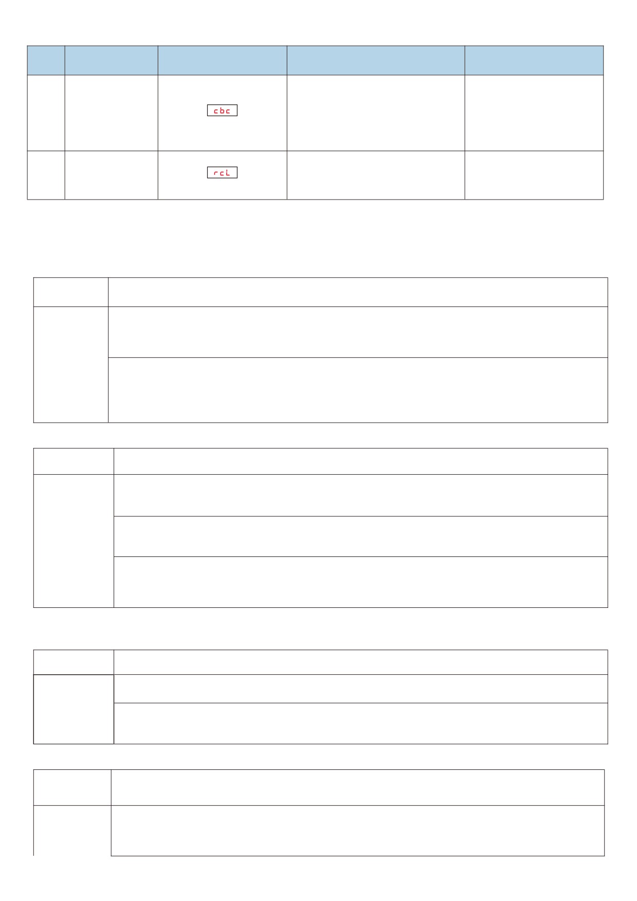
Countermeasures for fault
Sr. No.
Fault name
Operation panel display
Troubleshooting of cause of failure
handling
1. Reduce the load and check
1. Whether the load is too large or the
the motor and machinery
Wave - by - wave
electric machine is blocked
40
2. Choose the frequency
current limiting fault
2. The selection of frequency inverter is
inverter with higher power
small
level
Switching motor
1. Change the current motor selection
1. Switch the motor after the
41
failure during
through terminals during the
frequency inverter stops
operation
operation of the frequency inverter
6.2 Matters needing attention in commissioning:
1) How to shorten the actual acceleration time in V/F control mode?
Description of
If the actual acceleration time of the motor is found during the acceleration process, it is far greater than the set
phenomenon
acceleration time.
When the target frequency is less than 2 times of the rated frequency, the FF - 10 " over current suppression starting
current" can be increased, and the setting value of " over current suppression starting current" of the FF - 10
exceeds 170 each time, which is easy to cause " frequency inverter overload fault ol1" or " current limiting fault
CBC".
Solutions
The target frequency is more than 2 times of the rated frequency. In the process of rapid acceleration, it is likely that
the motor will stall (the output frequency of the frequency inverter has reached the target frequency, but the actual
speed of the motor has been staying at a certain speed in the medium speed section, but the actual speed of the
motor has been staying at a lower frequency or the acceleration time is too long). At this time, the FF - 13 "
compensation coefficient for high-speed over current suppression current" can be adjusted to 100 %.
2) How to shorten the actual deceleration time under V/F control mode?
Description of
If the actual deceleration time of the motor is found during deceleration, it is far greater than the set deceleration
phenomenon
time.
There is no additional braking resistor or feedback unit. Please increase F3 - 10 " V/F over excitation gain" setting
by 20 % each time. After increasing F3 - 10 “V/F over-excitation gain" setting, if the motor oscillation over-voltage
fault is caused, please reduce FF - 17 " over-voltage suppression voltage gain" setting.
The inverter is equipped with a braking resistor or an energy feedback unit, and the input voltage level of the
inverter is 360 - 420 v. Please adjust the FF - 32 " starting voltage of the braking unit" setting to 690 v and the F3
Solutions
- 10 " V/F over-excitation gain" setting to 0.
Using shutdown DC brake, recommended setting:
F6 - 07 ( stop DC brake starting frequency )
0.5 Hz
F6 - 09 ( stop DC brake current )
100 %
F6 - 10 ( stop DC brake time )
1S
3) How to limit the output current under V/F control mode and how to prevent over current fault under extreme impact
load?
Description of
In order to better protect the motor, control the upper limit of motor current
phenomenon
The current upper limit can be controlled by adjusting FF - 10 " over current suppression starting current" and "
current upper limit"
Solutions
Sudden acceleration, sudden deceleration, or impact load type may cause “over current fault oc" or " CBC current
limiting fault". Please increase FF - 12 " over current suppression gain" setting value. If the adjustment is too large,
it may cause current oscillation. At this time, please pay attention to callback.
4) How to limit bus voltage under V/F control mode to prevent over voltage fault?
Description of
In constant speed power generation loads (e.g. kowtow pumping units, stone sawing machines) and shock surge
phenomenon
loads (e.g. high-power punching machines), over-voltage faults can easily occur during operation.
Constant speed intermittent power generation load: please lower FF - 14 " over voltage suppression starting
voltage" setting value
(factory value
770 v) and limit the upper limit value of bus voltage without specific
Solutions
requirements. it is recommended to adjust it to about 720 v. if over voltage fault still occurs, please adjust ff - 18 "
over voltage suppression maximum rise limit frequency" setting value to 10 Hz or 20 Hz ( for example, load with
132

long cycle power generation time such as stone sawing machine ).
When an over voltage fault occurs in the sudden surge load, please lower the ff - 14 " over voltage suppression
starting voltage" setting and suggest to adjust it to about 720 v.
Large inertia rapid deceleration load: if the inverter is equipped with braking resistor and the input voltage level of
the inverter is 360 ~ 420 v, please adjust FF - 32 " starting voltage of brake unit" setting to 690 v and F3 - 10 " V/F
over-excitation gain" setting to 0. If the over voltage is still present, please lower the FF - 14 " over voltage
suppression start voltage" setting, which is recommended to be adjusted to about 740 v.
6.3 F0.01 = 2 ( V/F mode), common problem solving methods
Description of
Solutions
phenomenon
Motor oscillation during
{
Increase the oscillation suppression parameter ( F3 - 11 ) by 10 units ( maximum adjustment to
operation
100 );
High power start-up over -
{
Lower the torque increase (F3 - 01) and adjust downward by 0.5 %.
current reporting
The current in operation is
{
Set the rated voltage ( F1 - 02 ) and rated frequency ( F1 - 04 ) of the motor correctly;
too high
{
Lower the torque increase (F3 - 01) and adjust downward by 0.5 %.
{
appropriately increase the carrier frequency value ( F0 - 22 ) in units of 1.0 kHz;
Motor noise is high
{
( note: increasing the carrier frequency motor leakage current will increase )
{
Confirm that the over voltage suppression enable ( ff - 15 ) is set to the enable state; Increase the
Sudden unloading of
over voltage suppression gain ( ff - 16 / ff - 17, factory 30 ) by 10 units ( maximum adjustment to
heavy load to report over
100 );
voltage, deceleration to
{
Reduce the over voltage suppression operating voltage ( ff - 14 factory 760 v ) and reduce it in 10v
report over voltage
units ( minimum adjustment to 700 v );
{
Increase the over current suppression gain ( ff - 12 factory 20 ) by 10 units ( maximum adjustment
Surge overload to report
to 100 );
over - current, speed up
{
Reduce over current suppression starting current ( ff - 10 factory 150 % ), decrease in 10 %
reporting over - current
( minimum adjustment to 50 % );
6.4 Fault analysis and countermeasures
Panel
Name
Troubleshooting of cause of failure
Countermeasures for fault handling
display
There is a ground or short circuit in
● Eliminate peripheral faults and detect if short circuit occurs in the
the frequency inverter output
motor or interrupt contactor
circuit
The control mode is FVC or SVC
Accelerated
● Set motor parameters according to the motor nameplate to identify
OC1
and there is no parameter
over current
motor parameters
identification
Quick acceleration condition,
acceleration time setting is too
● Increase the acceleration time
short
133

Panel
Name
Troubleshooting of cause of failure
Countermeasures for fault handling
display
● Confirm that the over current suppression function (FF - 11 ) has
been enabled;
Setting of over-loss rate
● The setting value of over current suppression action current (FF - 10)
suppression is not appropriate
is too large and is recommended to be adjusted within 120 % to 150 %.
● The setting of over-current suppression gain (FF - 12 ) is too small,
and it is recommended to adjust within 20 to 40;
Manual torque boost or V/F curve
● Adjust the manual lifting torque or V/F curve
not appropriate
● Select speed tracking to start or wait for the motor to stop before
Start the rotating motor
starting
● Check the historical fault record. If the current value at the time of the
fault is far from the value of the over current point, it is necessary to
Subject to external interference
find the interference source. If there is no other interference source, it
may be the drive board or hall element.
There is a ground or short circuit in
● Eliminate peripheral faults and detect if short circuit occurs in the
the frequency inverter output
motor or interrupt contactor
circuit
The control mode is FVC or SVC
● Set motor parameters according to the motor nameplate to identify
and there is no parameter
motor parameters
identification
The deceleration time is set too
short under the condition of rapid
● Increase deceleration time
deceleration.
● Confirm that the over current suppression function (FF - 11 ) has
Deceleration
OC2
been enabled;
over current
Setting of over-loss rate
● The setting value of over current suppression action current (FF - 10)
suppression is not appropriate
is too large and is recommended to be adjusted within 120 % to 150 %.
● The setting of over-current suppression gain (FF - 12 ) is too small,
and it is recommended to adjust within 20 to 40;
Brake unit and brake resistor are
● Add brake unit and resistance
not added
● Check the historical fault record. If the current value at the time of the
fault is far from the value of the over current point, it is necessary to
Subject to external interference
find the interference source. If there is no other interference source, it
may be the drive board or hall element.
There is a ground or short circuit in
● Eliminate peripheral faults and detect if short circuit occurs in the
the frequency inverter output
motor or interrupt contactor
circuit
The control mode is FVC or SVC
● Set motor parameters according to the motor nameplate to identify
and there is no parameter
motor parameters
identification
Constant
Quick acceleration condition,
speed over
OC3
acceleration time setting is too
● Increase the acceleration time
current
short
● Confirm that the over current suppression function (FF - 11 ) has
been enabled;
Setting of over-loss rate
● The setting value of over current suppression action current (FF - 10)
suppression is not appropriate
is too large and is recommended to be adjusted within 120 % to 150 %.
● The setting of over-current suppression gain (FF - 12 ) is too small,
and it is recommended to adjust within 20 to 40;
134
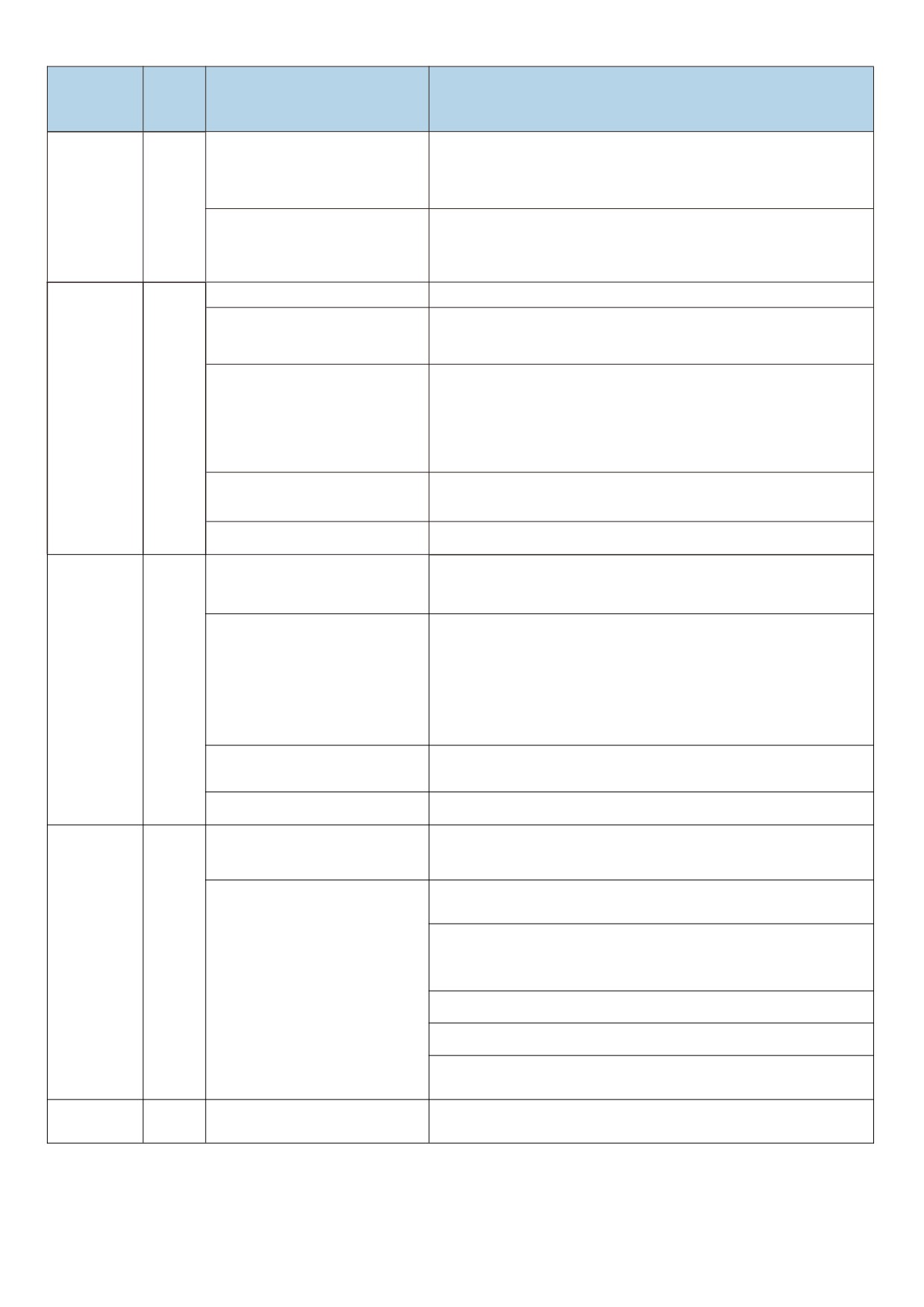
Panel
Name
Troubleshooting of cause of failure
Countermeasures for fault handling
display
● In stable operation, if the operating current exceeds the rated current
The selection of frequency inverter
of the motor or the rated output current value of the frequency inverter,
is small
please select the frequency inverter with higher power level.
● Check the historical fault record. If the current value at the time of the
fault is far from the value of the over current point, it is necessary to
Subject to external interference
find the interference source. If there is no other interference source, it
may be the drive board or hall element.
High input voltage
● Adjust the voltage to the normal range
There is an external force to drive
the electric machine to run during
● Cancel additional power or add braking resistance
acceleration
● Confirm that the over voltage suppression function (FF - 15 ) has
been enabled;
Accelerated
over voltage suppression setting is
● over voltage suppression action voltage (FF - 14 ) set value is too
OU1
over voltage
not appropriate
large, which is recommended to be adjusted within 770 v to 700 v;
● The over voltage suppression gain (FF - 15 / 16 ) is set too small and
is recommended to be adjusted within 30 to 50;
There is no additional braking unit
● Add brake unit and resistance
and braking electrical resistance
Acceleration time is too short
● Increase the acceleration time
There is an external force to drag
● Cancel additional power or add braking resistance
the motor during deceleration
● Confirm that the over voltage suppression function (FF - 15 ) has
enabled;
over voltage suppression setting is
● over voltage suppression action voltage (FF - 14 ) set value is too
Deceleration
OU2
not appropriate
large, which is recommended to be adjusted within 770 v to 700 v;
over voltage
● The over voltage suppression gain (FF - 15 / 16 ) is set too small and
is recommended to be adjusted within 30 to 50;
There is no additional braking unit
● Add brake unit and resistance
and braking electrical resistance
Deceleration time is too short
● Increase deceleration time
There is an external force to drag
● Cancel additional power or add braking resistance
the motor during deceleration
● Confirm that the over voltage suppression function (FF - 15 ) has
enabled
● over voltage suppression operation voltage (FF - 14 ) set value is too
Constant rate
large, and it is recommended to adjust within 770 v ~ 700 v;
OU3
over voltage
over voltage suppression setting is
● over voltage suppression gain (FF - 15 / 16 ) set too
not appropriate
● Small, and it is recommended to adjust it within 30 to 50;
● over voltage suppression maximum rise limit frequency ( ff - 18 )
● The setting is too small, it is recommended to adjust within 10 to 20;
Control power
The bus voltage fluctuates up and
● Low input voltage or low input power.
IPF
failure
down at the under voltage point
● seek technical support
135

Panel
Name
Troubleshooting of cause of failure
Countermeasures for fault handling
display
Electric
frequency
inverter The
display is
normal and
The fan is damaged or jammed
“EnEr”is
● Replace the fan
EnEr
There is a short circuit in the wiring
displayed
● Eliminate external short circuit fault
of the peripheral control terminal
after
operation.An
d stop the
machine
immediately
136
Chapter VII Maintenance
Danger
z
Do not repair and maintain the equipment with electricity, otherwise there is danger of electric
shock!
z
Confirm that maintenance and repair can only be carried out when the inverter bus voltage is
lower than DC36V, whichever is 10 minutes after the power failure. Otherwise, the residual
charge on the capacitor will cause harm to people!
z
Please restore the front cover plate of the connection terminal before re - powering, otherwise
it may cause personal injury!
z
All pluggable plug-ins must be plugged and unplugged in case of power failure. Otherwise,
there is a danger of causing secondary damage!
Danger
z
Parameters must be set after replacing the frequency inverter, otherwise it may cause damage
to other equipment in the system!
z
Anti-static measures must be taken to dismantle and install the circuit board, which can
prevent the damage of devices on the circuit board!
z
Non-professional technical personnel shall carry out electrical detection or measurement
during power-up or operation of the frequency inverter.
7.1 Maintenance and repair
7.1.1 Routine maintenance
Due to the influence of ambient temperature, humidity, dust and vibration, the devices inside the frequency
inverter will age, causing potential failure of the frequency changer or reducing the service life of the frequency
inverter. Therefore, it is necessary to carry out routine and regular maintenance and safeguard of the frequency
inverter.
Routine inspection items:
1) Whether the operating environment of the frequency inverter has changed.
2) Whether the frequency inverter is overheated or has abnormal sound, and whether the frequency inverter
cooling fan works normally.
3) Whether abnormal changes occur in the sound of the motor during its operation and whether vibration occurs
137
during its operation.
4) Whether the display value of the main operating parameters of the load is the same as the normal value.
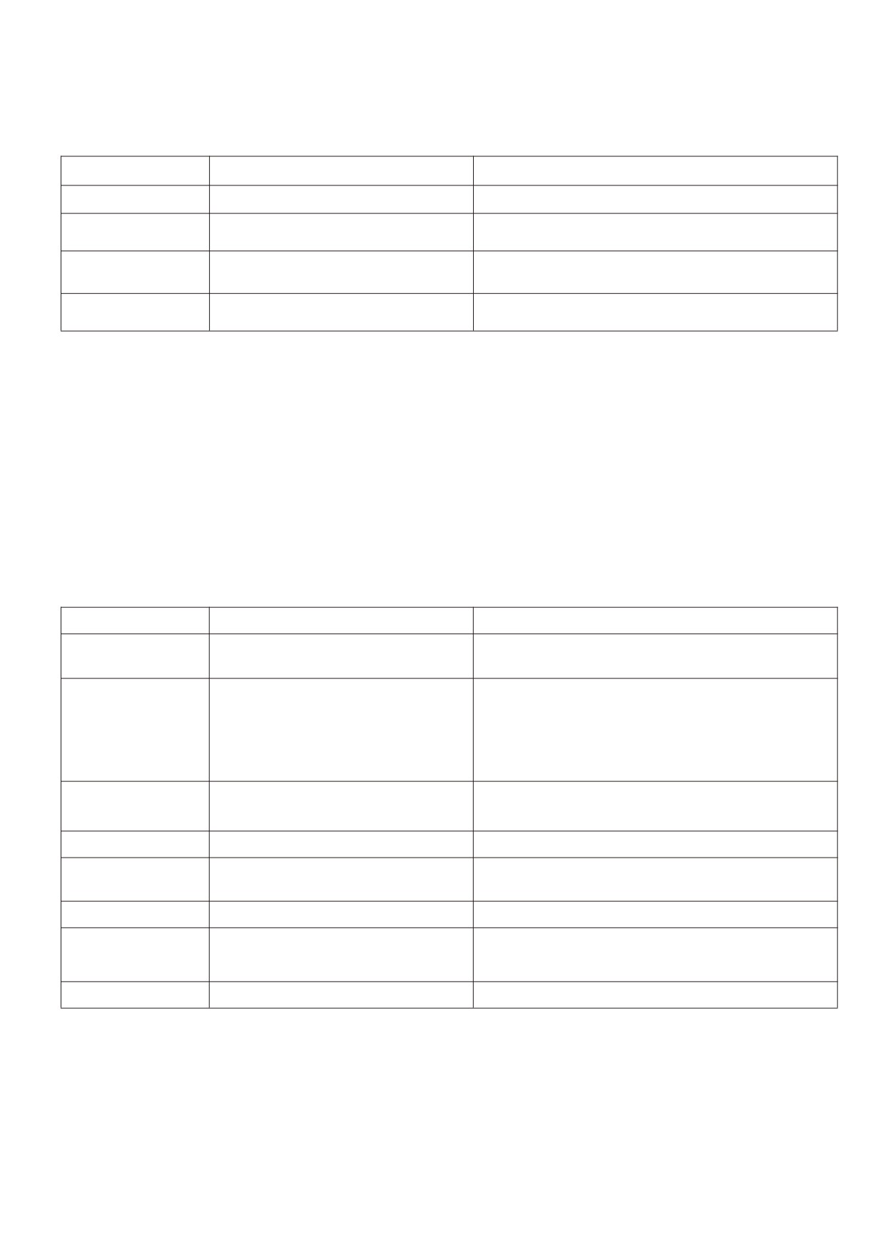
Refer to the following table for routine inspection:
Inspection items
Inspection area
Inspection items
Operating Environment
Frequency inverter installation site
Temperature, humidity, dust, metal dust, harmful gases
Frequency inverter
Inside the cabinet
Temperature, sound, peculiar smell
body
Whether the monitoring data is normal, such as input
Display
LED monitor, meter
voltage, output current, output frequency output voltage, etc.
Motor and its wiring and connection
The temperature and sound of the motor, the temperature of
Loads
terminals
the wire and whether there is abnormal heat at the terminal
Daily cleaning:
1) Keep the doors and windows of the frequency inverter room closed and the filtering device of the cooling
system in a normal and clean state.
2) The frequency inverter should always be kept in a clean state. Validly remove dust on the surface area of the
frequency inverter to prevent dust accumulation from entering the frequency inverter. Especially the metal dust
7.1.2 Regular maintenance
Regular inspections should be carried out at places that are difficult to inspect during operation. The inspection
shall be carried out at least ten minutes after the power failure. Refer to the following table for regular inspection
items:
Inspection items
Check content
Countermeasures
Main loop terminal,
Whether the bolts and screws are loose,
Processing is normal
control loop terminal
and whether there are any spark marks
Whether there is dust accumulation,
whether the fan blade movement is
blocked or whether there is abnormal
Fan cooling
Replace defective products
sound and vibration, and whether the wind
turbine housing is overheated and
deformed
Whether there is overheating or burning.
The former changes plates as the case may be, while the
Printed circuit board
Dust accumulation
latter blows the ash OFF with dry air of several atmospheres
Connector
Is it loose
Reinsert
Is there any leakage or bubbling
Electrolytic capacitor
Replace with new products
discoloration?
Heat sink
Is there dust accumulation
Dust removal, air duct cleaning,
Use a 500 v megohmmeter and disconnect the control
Insulation situation
Insulation of main circuit to ground
circuit from the main return circuit, the power supply and the
load from the frequency inverter
Ambient air
Is it corroded
Transforming the environment
7.1.3 Replacement of vulnerable parts of frequency inverter
The vulnerable parts of the frequency inverter mainly include cooling fans and electrolytic capacitors for filtering,
followed by printed circuit boards and fuses, etc. their life span is closely related to the environment in which they are
used and their maintenance conditions. The user can determine the replacement period based on the running time.
The typical life time of these devices is:
138
Device name
Life time
Fan
2-3 years
Electrolytic condenser
4-5 years
Printed circuit board
5-8 years
1) Fan cooling
Possible causes of damage: bearing wear and blade aging. Criteria: whether there is any crack in the fan
blade, whether there is abnormal vibration sound when starting the machine, etc.
2) Filter electrolytic capacitor
Possible causes of damage: poor quality of input power supply, high ambient temperature, frequent load jump
and electrolyte aging. Criteria: leakage of liquid, bulging of safety valve, determination of electrostatic capacitance,
determination of insulation resistance
3) Printed circuit board
Possible causes of damage: aging insulation, deterioration of devices, loose connectors.
Criteria: broken insulation, burning marks on board surface, poor contact of plug - ins.
7.2 Storage
After the user purchases the frequency inverter, the following points must be paid attention to for temporary
storage and long-term storage:
y When storing, try to pack it into the packing box of our Company according to the original packing.
y It should be placed in a room with a temperature of - 25 ℃ ~ 65 ℃ without moisture, dust, metal dust and good
ventilation.
y Long - term storage will lead to deterioration of the electrolytic capacitor of the main circuit in the frequency
inverter. It must be guaranteed to be energized once within one year to ensure that the electrical characteristics
of the capacitor can be restored.
y Do not carry out withstand voltage test on the frequency inverter at will, which will lead to reduced service life.
139
Chapter VIII Peripheral equipment
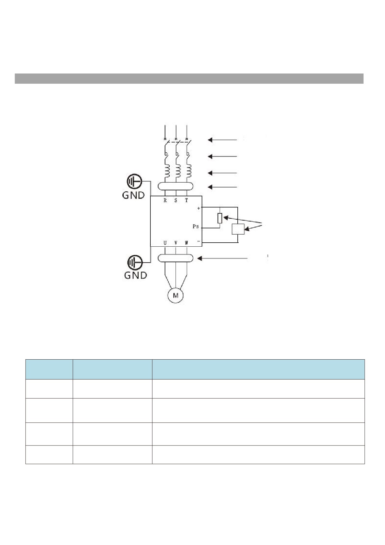
8.1 Peripheral equipment and optional parts connection diagram
Three - phase power supply
Fuse - less circuit breaker
MCCB
Magnetic contactor
MC
Ac reactor ACL
Radio noise filter Nf
HV610
Brake unit UB or resistor RB
Radio noise filter NF
8.2 Functional description of peripheral equipment
Accessory name
Installation site
Brief description of function
Fuse - less
Front end of input loop
Power cut-off for downstream equipment when over current occurs
circuit breaker
Between the idle switch and
Contactor
the input side of the
Cut OFF the main power supply when the frequency inverter fails.
frequency inverter
Input side of frequency
Increasing the power factor at the input side; validly eliminate the higher
Ac input reactor
inverter
harmonic on the input side
Brake unit or
Main circuit of frequency
Mainly used for fast braking
brake resistor
inverter
140
The output side of the frequency changer contains as many higher order
harmonic waves as possible. When the motor is far away from the frequency
Between the frequency
inverter, there is a large distributed capacitance in the circuit. One of the
Ac output
inverter output side and the
harmonics may resonate in the loop, bringing about two effects: Damaging the
reactor
motor. Install near the
insulation performance of the motor will damage the motor for a long time. A large
frequency inverter.
leakage current is generated, causing frequent protection of the frequency
inverter. As the distance between the frequency inverter and the motor exceeds
100 m, it is proposed to install an output AC reactor.
Reduce the transmission and radiation interference of the frequency changer to
Input side of frequency
the outside; Reduce the transmission and conduction interference from the power
EMC input filter
inverter
supply end to the frequency inverter and improve the anti-interference capability
of the frequency inverter.
Leakage
Input side of frequency
To protect the frequency inverter and related circuit leakage
protector
inverter
Main circuit of frequency
It is used in occasions where the power is cut OFF for a long time and the motor is
Capacitance box
inverter
continuously transported.
8.2.1 No fuse circuit breaker and contactor
1 ) The basic purpose of the fuse-less circuit breaker ( commonly known as air switch ) is to quickly cut OFF
the fault current when the frequency inverter has an over current fault or other circuits below it have the same fault.
It is used to prevent the frequency inverter and its circuits from causing power failure and to prevent the expansion
of local accidents. In general power distribution systems, each should be equipped with its rated current varying
according to the capacity of the frequency inverter. Refer to the table below for the recommended selection.
2) The contactor cuts OFF its main power supply when the frequency inverter fails and is used to prevent
restart after the failure.
Frequent power-up and power-down operations (less than twice per minute) or direct start-up operations of the
inverter through contactors should be avoided.Because the contactor is connected between the power supply and
the input of the frequency inverter, if the contactor is used to control the starting and stopping of the frequency
inverter, frequent charging and discharging can easily reduce the service life of the capacitor in the frequency
inverter and also damage the contactor. Switch devices such as contactors shall not be installed between the output
end of the frequency inverter and the motor. If it is really necessary (for example, switching between multi-frequency
inverter systems or multi-motor systems), the on-off operation of the frequency inverter shall be ensured when there
is no output, otherwise the main device in the frequency inverter may be damaged.
The recommended selection is shown in the following table.
Inverter specification
Fuse - less circuit breaker mccb ( a )
Contactor MC ( a )
3 - phase power supply, 380 v
4
9
HV610-R75G3
6
9
HV610-1R5G3
10
12
HV610-2R2G3
16
18
HV610-004G3
20
25
HV610-5R5G3
25
25
HV610-7R5G3
32
32
HV610-011G3
40
40
HV610-015G3
50
50
HV610-018G3
63
63
HV610-022G3
80
80
HV610-030G3
100
100
HV610-037G3
125
115
HV610-045G3
160
125
HV610-055G3
200
185
HV610-075G3
225
225
HV610-093G3
315
330
HV610-110G3
141
315
400
HV610-132G3
350
400
HV610-160G3
400
500
HV610-185G3
400
500
HV610-200G3
500
500
HV610-220G3
500
630
HV610-250G3
630
630
HV610-280G3
750
750
HV610-315G3
800
800
HV610-355G3
800
800
HV610-400G3
1000
1000
HV610-450G3
1250
1250
HV610-500G3
1600
1600
HV610-560G3
8.2.2 AC input reactor
The device aims to change the voltage waveform distortion caused by the capacitive characteristics of the input
end of the frequency inverter, validly eliminate the high-order harmonic wave on the input side and suppress the
surge on the power supply side, thus improving the power factor, preventing other devices from being damaged due
to the voltage waveform distortion, and eliminating the input current imbalance caused by the unbalance between the
power supply phases. In addition, the higher harmonics of the power supply will cause damage to the frequency
inverter.
8.2.3 AC output reactor
When the connection between the frequency inverter and the motor is too long, the distributed capacitance
between the cables will increase, which is easy to generate capacitive high harmonic current, which will directly
cause the output over current accident of the frequency inverter. It will also cause electromagnetic interference to
other devices. Therefore, adding output reactors can reduce these impacts. As for the distributed capacitance
between the output wiring of the frequency inverter, if the high harmonic current content in the wiring is high, it may
cause resonance and generate leakage current. Leakage currents exceeding 100 m in length of motor cables may
also be large. The solution is to reduce carrier frequency operation, and a more valid measure is to install output
reactors.
It is recommended to use AC reactors under the following circumstances:
1) The power supply capacity of the frequency inverter is more than ten times that of the frequency inverter.
2) The same power supply as the frequency inverter is connected with a thyristor load or a power factor
compensation device controlled by a switch, etc. where the quality of the power grid is relatively poor.
3) The three-phase unbalance degree of the power supply is greater than 3 %.
The recommended reactor parameters are shown in the following table.
Frequency inverter power ( kw )
Inlet wire reactor
Inlet wire electricity
Output reactor electricity
Output reactor inductance ( μ
(Rated voltage 380V)
Current ( a )
Inductance ( MH )
Stream ( a )
H)
0.75
3.4
8.0
2.1
2100
1.5
4.8
4.0
3.8
2100
2.2
6.2
3.2
5.1
1450
4.0
9.6
2.0
9
1100
5.5
14
1.5
13
800
7.5
18
1.2
17
650
11
26
0.8
25
330
15
35
0.6
32
250
18.5
41
0.5
37
200
22
50
0.42
45
180
30
62
0.32
60
90
37
80
0.26
75
80
45
96
0.21
91
60
142

55
120
0.18
112
40
75
165
0.13
150
35
93
180
0.11
176
30
110
225
0.09
210
20
132
260
0.08
253
16
160
305
0.07
304
13
185
350
0.06
340
11
200
385
0.06
380
11
220
430
0.05
426
9
250
470
0.04
465
9
280
530
0.03
520
8
315
600
0.03
600
6
355
700
0.03
700
5
400
800
800
5
0.03
450
1000
0.02
1000
4
500
1250
0.02
1000
3
560
1600
0.02
1250
3
8.2.4 Selection of energy consumption braking unit and braking resistance
When the motor is operating in the braking state, the motor will generate regenerative energy, which is
electrical energy converted by the mechanical energy released when the rotating speed of the rotating motor
changes from high to low and fed back to the main circuit being powered, which raises the voltage of the main
circuit. The amount of the energy depends on the overall system characteristics and the parameter settings of the
frequency inverter. In order to make the system work properly, this part of energy is dissipated by resistance, i.e.
DC energy consumption braking.
1) The selection of the resistance value of the braking resistor RB
It also indirectly determines the magnitude of the braking torque of the system. If the braking torque is too small,
it will not be restrained. The rise in the voltage of the main circuit will lead to over-voltage of the main circuit of the
system and trip protection. If the braking torque is too large, the stable operation of the system will be affected. In
order to stabilize the braking voltage of the system, it is generally chosen to be about 1.8 times of the rated AC input
voltage. For 380 v standard motor control system, the working point of energy consumption braking is generally
selected to be about 700 v. If this voltage is too low, braking may occur within the maximum operating range of the
power supply. If this voltage is selected too high, over voltage protection action may occur.
Assuming KB is the mechanical energy / electrical energy conversion efficiency coefficient when the motor
power is p (kw) feedback, usually kb = 0.7, then, when the brake operating point voltage u = 700 volts, according
to the energy conservation relation that the motor generates energy that is completely absorbed by the brake
resistor, the following relation exists when the motor has 100 % brake torque:
1000P*KB=U²/RB
That is,
RB= U²/1000 P*KB=700/P
Considering that KB is an empirical value and the duty cycle of the braking current, the actual maximum braking
torque occurs at the extreme limit of KB = 1, at this time: KBmin = 0.7 * 700 / P ≈ 500 / P at this time, the braking
current reaches the maximum. If this limit is exceeded, the device will be damaged.
2) The selection of braking resistor power
For the calculation of the power dissipated by the braking resistor itself is still fully absorbed by the braking
resistor according to the regenerative energy and uses thermal energy. Considering the form of release, assuming
that the resistance power is PB, the braking frequency KF, and the power margin ks, then
PB=P*KB*Kf*Ks
143

If select the Ks is 10/0.7, then KB*Ks=1, then, the heat dissipation power of PB=P*Kf
Brake resistance depends on the braking frequency Kf. For general use, when occasional braking is required
and braking does not need to occur frequently, Kf should be around 10%.For different load types, the values are
usually as follows:
Oil field beam pumping unit: 10 % - 20 %
Elevators and cranes: 20 % - 40 %
Uncoilers and winders: 30 % - 50 %
Centrifuges: 40 % - 60 %
Since the regenerative braking energy varies according to the inertia, deceleration time, load type, braking
frequency and other factors of the driving system, the selection of braking resistance should be based on the actual
usage of the user. Generally speaking, the larger the inertia of the system, the faster the deceleration and the more
frequent the breaking, the smaller the resistance value selected and the greater the power of the resistor itself. The
recommended values are shown in the following table.
Braking resistance
Braking resistance
Braking resistance
Braking resistance
Motor power
Power supply
value(W/Ω)
quantity
value(W/Ω)
quantity
Note
(kW)
Kf=20%
Kf=20%
Kf=40%
Kf=40%
380V/3Φ
0.75
150W/800Ω
1
300W/800Ω
1
Built - in brake unit
380V/3Φ
1.5
300W/400Ω
1
600W/400Ω
1
Built - in brake unit
380V/3Φ
2.2
440W/250Ω
1
880W/250Ω
1
Built - in brake unit
380V/3Φ
4.0
800W/150Ω
1
1100W/150Ω
1
Built - in brake unit
380V/3Φ
5.5
1100W/100Ω
1
2200W/100Ω
1
Built - in brake unit
380V/3Φ
7.5
1500W/75Ω
1
3000W/75Ω
1
Built - in brake unit
380V/3Φ
11
2200W/50Ω
1
4500W/50Ω
1
Built - in brake unit
380V/3Φ
15
3000W/40Ω
1
6000W/40Ω
1
Built - in brake unit
380V/3Φ
18.5
4000W/30Ω
1
4000W/60Ω
2
Built - in brake unit
380V/3Φ
22
4500W/30Ω
1
4500W/60Ω
2
Built - in brake unit
380V/3Φ
30
6000W/20Ω
1
6000W/40Ω
2
External brake unit
380V/3Φ
37
4000W/28Ω
2
5000W/42Ω
3
External brake unit
380V/3Φ
45
4500W/20Ω
2
6000W/30Ω
3
External brake unit
380V/3Φ
55
5500W/16Ω
2
5000W/40Ω
5
External brake unit
380V/3Φ
75
5000W/19Ω
3
5000W/39Ω
6
External brake unit
380V/3Φ
93
6000W/15Ω
3
5000W/40Ω
8
External brake unit
380V/3Φ
110
5500W/18Ω
4
5000W/40Ω
9
External brake unit
380V/3Φ
132
4500W/22Ω
6
6000W/33Ω
9
External brake unit
380V/3Φ
160
4000W/24Ω
8
5000W/39Ω
13
External brake unit
380V/3Φ
185
4500W/20Ω
8
5000W/39Ω
15
External brake unit
380V/3Φ
200
5000W/20Ω
8
5000W/40Ω
16
External brake unit
380V/3Φ
220
5000W/20Ω
9
5000W/40Ω
18
External brake unit
380V/3Φ
250
5000W/20Ω
10
5000W/38Ω
20
External brake unit
380V/3Φ
280
5000W/20Ω
11
5000W/41Ω
23
External brake unit
380V/3Φ
315
5000W/20Ω
13
5000W/39Ω
26
External brake unit
380V/3Φ
355
5000W/20Ω
14
5000W/42Ω
30
External brake unit
380V/3Φ
400
5000W/20Ω
16
5000W/38Ω
32
External brake unit
380V/3Φ
450
5000W/18Ω
18
5000W/36Ω
36
External brake unit
380V/3Φ
500
5000W/18Ω
20
5000W/36Ω
40
External brake unit
380V/3Φ
560
5000W/18Ω
22
5000W/36Ω
45
External brake unit
3) Regarding the brake unit
No regenerative braking function is built in the 30kw G series type of frequency inverter and above specifications.
When braking energy is needed, an energy consumption braking unit should be added. It should be noted when
ordering. The brake unit shall be connected to the Θ and ⊕ terminals of the frequency inverter, and the brake
resistor shall be connected to the external brake unit. The regenerative braking function is necessary when the
braking torque of the machine itself cannot meet the application requirements, especially when it is under large
inertia load, frequently broken or quickly stopped.
In situations requiring higher fast braking, even if an energy-consuming braking device is installed, the user is
advised to use a feedback braking unit.
144

8.2.5 External DC reactor
The series of frequency inverters are all externally connected with DC reactors. If necessary, please consult the
distributor or the factory directly for specific specifications.
8.2.6 Radio noise filter
The product is designed to meet the requirements of national standard GB/T12668.3 in terms of electromagnetic
compatibility (that is, EMC refers to the ability of electrical equipment to operate in an electromagnetic interference
environment, not to interfere with the electromagnetic environment, and to realize its functions stably). Frequency
inverters need to meet the requirements of both electromagnetic interference and anti-electromagnetic interference.
Electromagnetic interference mainly refers to radiation interference, conduction interference and harmonic
interference of frequency inverters. Anti-electromagnetic interference mainly refers to the conduction immunity,
radiation immunity, surge immunity, rapid burst immunity, ESD immunity and low frequency end immunity of the
power supply.
The Company's products will be installed and used according to the following instructions, and will have good
electromagnetic performance in general industrial environment.
There are two kinds of electromagnetic interference, one is the interference of the electromagnetic noise of the
surrounding environment to the frequency inverter, and the other is the interference of the noise generated by the
frequency inverter to the surrounding equipment.
1) Treatment method for interference of peripheral electromagnetic equipment to frequency inverter: Generally,
the electromagnetic influence on frequency inverters is caused by the installation of a large number of relays,
contactors or electromagnetic brakes in the vicinity of frequency inverters. When the frequency inverter is thus
disturbed and misoperation occurs, it is recommended to install a radio noise filter at the input of the frequency
inverter.
2) Measures for dealing with interference of frequency inverter to peripheral equipment: This part of the noise is
divided into two types: one is the frequency inverter radiation interference, while the other is the frequency
inverter conduction interference. These two kinds of interference make the peripheral electrical equipment
subject to electromagnetic or electrostatic induction. Thus causing misoperation of the device According to
different interference situations, adopt different methods to solve the problem:
a. The instruments, receivers and sensors used for measurement are generally weak in signal. If they are
relatively close to the frequency inverter or in the same control cabinet, they are prone to interference and
misoperation. Therefore, they should be kept away from the interference source as far as possible. do not
arrange the signal lines in parallel with the power lines, especially do not tie them together in parallel; Shielded
wires for signal lines and power lines and good grounding; Ferrite magnetic rings are added to the output side of
the frequency changer (the selective suppression frequency is in the range of 30 - 1000 MHz) and 2 - 3 turns
are wound in the same direction. For severe cases, the radio noise output filter can be added.
b. When the interfered equipment and the frequency inverter use the same power supply, they will cause
conduction interference. If the above methods cannot eliminate interference, a radio noise filter should be
installed between the frequency inverter and the power supply.
c If the length of the motor cable exceeds 100 m, it is required to add an output filter. The rated voltage of
the frequency inverter is 380 v and the recommended products for the input radio noise filter are shown in the
following table.
Adaptive motor power ( kw )
Power supply capacity ( kVA)
Rated input current (A)
0.75
1.5
3.4
1.5
3
5
2.2
4
5.8
4.0
5.9
10.5
5.5
8.9
14.6
7.5
11
20.5
11
17
26
15
21
35
18.5
24
38.5
22
30
46.5
30
40
62
37
57
76
145
45
69
92
55
85
113
75
114
157
93
134
180
110
160
214
132
192
256
160
231
307
185
242
350
200
250
385
220
280
430
250
355
465
280
396
525
315
445
590
355
500
660
400
540
780
450
630
885
500
700
920
500
760
1050
Precautions for installation:
1) The grounding wire of frequency inverter and other electrical products shall be well grounded; the
filter must be connected to the same common ground as the PE end of the frequency inverter, otherwise it
will seriously affect the EMC effect. The input filter is installed as close as possible to the power input of the
frequency inverter.
Shield cables for the control signal lines and lead wires of the test lines of the frequency inverter and
reliably ground the shield layer.
2 ) The power input and output lines and weak current signal lines ( e.g. control lines ) of the frequency
inverter should not be arranged in parallel as far as possible, and should be arranged vertically when
conditions permit.
3) It is recommended to use shielded cable or steel pipe to shield the power line for the output power
line of the frequency inverter, and the shielding layer should be reliably grounded.
4) It is recommended to use twisted pair shielding control lines for the leads of the interfered equipment
and reliably ground the shielding layer;
5) If peripheral equipment is grounded separately, interference caused by leakage current of frequency
inverter grounding line can be eliminated.
8.2.7 Leakage protector
There are two forms of leakage current when using frequency inverter: one is leakage current between wires,
the other is leakage current to ground. The former leakage current has been explained in the section of reactor. This
section only discusses leakage current to floor drain.
There may be insulation and leakage for other reasons in the frequency inverter and its accessories and related
circuits. Moreover, because there are distributed capacitors in the frequency inverter, the motor and its wiring with
the earth, the larger the distributed capacitor is, the larger the leakage current is. However, this series frequency
inverter is designed with low noise, so the carrier frequency is higher, the higher the carrier frequency is, the greater
the leakage current is. The leakage current will increase as the return current increases, so when the motor power
is high, the corresponding leakage current will be high. Validly reduce the distance between the frequency inverter
and the motor to reduce the distributed capacitance. The carrier frequency can be lowered to reduce leakage current,
but lowering the carrier frequency will result in increased motor noise. Installing reactors is also a valid way to solve
leakage current. However, there must be a current to the floor drain. Installing a leakage protector is also a valid
method to protect the frequency inverter.
The leakage protector shall be installed between the incoming line end of the frequency inverter and the mccb of
146
the air switch. The criterion for selecting its specifications is that the operating current of the leakage protector shall
not be less than ten times that of the line when the frequency inverter is not used under the power frequency power
supply.
8.2.8 Capacitance box
This peripheral device is specially used for occasions where the power failure time is long and the motor needs
continuous operation. Although this series frequency inverter has the advanced function of instant stop, the capacitor
box can still be used under the special circumstances of specific requirements (the instantaneous power failure of the
power supply is greater than 20 ms). If necessary, specify the specific requirements when ordering.
Since the installation of this external device will affect some parameters in the machine, so you do not want
users to install it themselves. Please contact our Company.
147
Chapter IX Quality Assurance
9.1 Quality commitment
The quality assurance of the product shall be handled according to the following regulations:
The warranty scope only refers to the frequency inverter body, and the warranty period starts from the
Company's delivery date.
The warranty period of the product is 18 months after purchase, even if the product fails due to the following
reasons Inside, also belong to paid maintenance:
z
Problems caused by incorrect operation or unauthorized self-repair and renovation;
z
Problems caused by the use of frequency inverters beyond the standard specification requirements;
z
Damage caused by falling or rough handling after purchase;
z
Aging or failure of devices caused by use in environments that do not meet the requirements of this
specification;
z
The frequency inverter is damaged due to incorrect connection wires;
z
Failures caused by earthquakes, fires, geomantic disasters, lightning strikes, abnormal voltages or other
natural disasters and disasters.
The Company has the right to entrust others to take care of the warranty of the faulty products.
The quality assurance content that is truly the responsibility of the Company:
z Return, exchange and warranty within one month of shipment;
z Replacement and warranty within three months of shipment;
z Warranty for 18 months after shipment
Relevant service fees shall be calculated based on actual fees. If there is any agreement, the principle of
agreement first shall be applied.
The Company's sales, production and agency agencies throughout the country can provide after-sales service
to the product.
Our Company reserves the right to interpret this agreement.
148
Additional instructions
Additional instructions
On the issue of exemption from liability
z
The Company cannot bear any liability arising from or induced by the use of the product in violation of the
provisions of this specification.
z
The Company is not responsible for compensation for the loss, ripple or secondary damage caused to you by
the failure of the product.
Instructions for users
This instruction manual is only applicable to this series of products.
The Company has lifelong responsibility for the product and provides all services related to the use of the
product.
Although the product is designed and manufactured under strict quality control, please ask our Company in
advance if it is used for the following purposes that may endanger human body or its life due to its failure or
operational error.
z Used for the transportation equipment
z Medical device
z Nuclear and electrical equipment
z Aviation and space devices
z Various safety devices
z Other special purposes
About hope for users
We sincerely hope that the vast number of users will put forward their opinions or suggestions on the Company's
product design, performance, quality and service, and we would appreciate it very much.
149
Appendix A Introduction of Communication
HV610 provides standard RS485 communication interface and realizes communication link through MODBUS
communication protocol. Through PC / PLC and other upper computers, network control of " single / Multi-Agent "
can be realized ( setting frequency inverter control command and operating frequency, modifying functional
parameters, monitoring frequency inverter operating status and fault information ) to adapt to specific application
requirements.
1 Basic communication settings
1.1 Select communication protocol
MODBUS is only supported by default for standard products that choose communication protocols. If other
communication protocols are required, you need to purchase another communication card and set FD - 00 and
related parameters..
FD - 00 communication protocol
0~3【0】
0: MODBUS protocol
1.2 Setting data transmission rate
Data transmission rate refers to the data transmission rate between
the frequency inverter
and the
upper
computer.
FD - 01 communication baud rate
0~0005【0005】
Protocol baud rate of MODBUS bits 0: 300 bps
1:600BPS
2:1200BPS
3:2400BPS
4:4800BPS
5:9600BPS
6:19200BPS
7:38400BPS
8:57600BPS
9:115200BPS
1.3 Set data format
FD - 02 data format
0~3【0】
0: No check: data format < 8,N,2 > (1 - bit start bit, 8 - bit data bit, 2 - bit stop bit, no check)
1: Even check: data format < 8, E, 1 > ( 1 bit start bit, 8 bit data bit, 1 bit stop bit, even check )
2: Odd check: data format < 8, O, 1 > ( 1 bit start bit, 8 bit data bit, 1 bit stop bit, odd check )
3. No check: data format < 8, N, 1 > ( 1 - bit start bit, 8 - bit data bit, 1 - bit stop bit, no check )
Note: The data format of the frequency inverter and the master station must be the same, otherwise normal
communication will not be possible.
1.4 Set the local address
FD - 03 set the local address
0~247【1】
In Modbus communication, a maximum of 247 units can be connected to the network. The address of each
frequency inverter must be unique.
1.5 communication timeout and response
FD - 05 communication timeout
0.1~60.0s【0.0s】
When FD - 05 = 0.0, the communication timeout detection is invalid.
150
When FD - 05 is non - zero, then the time between the current command and the next communication command
exceeds the FD - 05 setting, then the frequency inverter will fail to communicate and the operation panel will display
cof.
2 Modbus protocol description
2.1 protocol description
Protocol brief introduction
① Modbus master slave protocol. Only one device can send commands in the network at any time.
② The master station exchanges management information by polling the slave stations. No slave station can
send messages without the approval of the master station. If there is an error in data exchange, if the master station
does not receive a response, the slave station absent from the poll will be interrogated again.
③ If the slave station cannot recognize the information sent by the master station, it will send an abnormal
response to the master station.
④ If there is no direct communication between the slave station and the slave station, one slave station's data
must be read out through the master station's software and sent to another slave station Two types of dialogues can
be realized between the master station and the slave station:
The master station sends a request to the slave station and waits for the slave station to respond.
The master station sends requests to all slave stations without waiting for their response broadcast mode.
Transfer
The transmission mode is RTU (remote terminal unit) mode, and the frame does not contain any message
header bytes or message word segment terminators. The classic RTU frame format is shown in the following table:
Slave address
Function code
Data
CRC
1 byte
1 byte
0 ... 252 bytes
CRC low bit
① Address 0 (reserved), used for broadcasting.
② All slave nodes must identify the broadcast address of the write function but do not need to respond.
③ The master node does not have a specific address, only the slave node must configure the address.
RTU transmission method has four character formats, as follows:
① 1 - bit start bit, 8 - bit data bit, 2 - bit stop bit, no check
② 1 - bit start bit, 8 - bit data bit, 1 - bit stop bit, even check
③ 1 - bit start bit, 8 - bit data bit, 1 - bit stop bit, odd check
④ 1 - bit start bit, 8 - bit data bit, 1 - bit stop bit, no check
Characters or bytes are transmitted from left to right, as shown in the following table:
< - least significant bit ( LSB )
Most significant bit ( msb ) - >
Starting bit
1
2
3
4
5
6
7
8
Stop bit
Stop bit
Starting bit
1
2
3
4
5
6
7
8
Even check
Stop bit
Starting bit
1
2
3
4
5
6
7
8
Odd check
Stop bit
Starting bit
1
2
3
4
5
6
7
8
Stop bit
-
The above table shows that RTU transmission mode
Information frames are separated by at least at static interval of 3.5 bytes. The entire frame must be transmitted
in a continuous stream of bytes. If the interval between more than two frames is less than 3.5 bytes, the receiving
device will mistakenly assume that the slave station address of the second frame is the continuation of the previous
frame. CRC check failed due to frame disorder, resulting in communication failure. If the rest interval between two
bytes exceeds 1.5 bytes, the receiving device will consider the information frame incomplete and discard it.
151

2.2 MODBUS communication interface
Modbus realizes communication through RS485 interface, that is, through 485 + / 485 - link on the control panel.
2.3 MODBUS function and information format
Modbus's main function is to read (read) and modify (write) parameters. Different function instructions determine
different operation requests. The MODBUS function of HV610 is shown in the following table:
Functional instruction
Function name
Broadcasting
Maximum value of N
0x03
Reading N register words
No
16
0x06
Modify a register ( power down save )
Yes
1
0x05
Modify a register ( power down does not save )
Yes
1
Different function commands determine different Modbus information formats, as follows:
Starting word address
Word number
CRC16
Slave number
0x03
High | low
High | low
Low | high
Function instruction 3 _ host request
Bytes
Starting word value
-
Last word value
CRC16
Slave number
0x03
High | low
High | low
-
High | low
Low | high
Function command 3 _ host response
Starting word address
Data
CRC16
Slave number
0x06
High | low
High | low
Low | high
Function instruction 6 _ host request and slave response (same format)
Starting word address
Data
CRC16
Slave number
0x05
High | low
High | low
Low | high
Function instruction 5 _ host request and slave response (same format)
152

Function example
Function 0x03: read n register words, read range 1 ~ 16
The slave address is 01h, and two consecutive data words are read first. The starting address is F000H of the
communication parameter register. The structure of the frame is described as follows:
Message start
3.5 bytes of transmission time
Slave address
0 1H
Modbus function code
0 3H
Starting address high byte
F 0H
Starting address low byte
0 0H
High byte of data
0 0H
Low byte of data
0 2H
CRC low byte
F 7H
CRC high byte
0 BH
End of message
3.5 bytes of transmission time
Function instruction 0x03 requests frame
Message start
3.5 bytes of transmission time
Slave address
0 1H
Modbus function code
0 3H
High number of data bytes
0 0H
Low number of data bytes
0 4H
Register F000H data high byte
0 0H
Register F000H data high byte
0 BH
Register F000H data high byte
0 0H
Register F000H data high byte
0 0H
CRC low byte
CRC high byte
End of message
3.5 bytes of transmission time
Function instruction 0x03 slave responds to frame
Function
0x06: modify a register word.
Note: frequent write operations can damage internal memory!
① Execute the write command, and the data will be written into the internal register. The memory has a limit on
the number of write operations. If the limit is exceeded, the memory address will be destroyed. Please avoid frequent
write operations.
② If it is necessary to write to an address frequently, it is recommended to use function instruction 0x05.
153
Example: slave address is 01h. Now modify the contents of a register. Its communication register address is
f08h, and the written content is 1388 H. The structure of the frame is described as follows:
Message start
3.5 bytes of transmission time
Slave address
01H
Modbus function code
06H
Starting address high byte
F0H
Starting address low byte
08H
High byte of data
00H
Low byte of data
01H
CRC low byte
FCH
CRC high byte
C8H
End of message
3.5 bytes of transmission time
Function
0x06 host requests
Message start
3.5 bytes of transmission time
Slave address
01H
Modbus function code
06H
Starting address high byte
F0H
Starting address low byte
08H
High byte of data
00H
Low byte of data
01H
CRC low byte
CFH
CRC high byte
C8H
End of message
3.5 bytes of transmission time
Function
0x06 slave responds.
Function
0x05: modify a register word and write it into ram.
Note: the write operation instruction only modifies ram, does not store internal memory, and does not
save when power fails!
Example: slave address is 01h, now modify the contents of a register whose communication register address is
f08h, written in the content is 01h. The structure of the frame is described as follows:
Message start
3.5 bytes of transmission time
Slave address
01H
Modbus function code
05H
Starting address high byte
F0H
154
Starting address low byte
08H
High byte of data
00H
Low byte of data
01H
CRC low byte
BEH
CRC high byte
C8H
End of message
3.5 bytes of transmission time
Function 0x05 host requests
Message start
3.5 bytes of transmission time
Slave address
01H
Modbus function code
05H
Starting address high byte
F0H
Starting address low byte
08H
High byte of data
00H
Low byte of data
01H
CRC low byte
BEH
CRC high byte
C8H
End of message
3.5 bytes of transmission time
Function 0x05 slave responds.
Fault code and exception code
If the slave successfully receives a request but cannot execute it, the slave will return an exception response
containing the fault code and the exception generation code, informing the host of the error message.
The fault code format is in two formats:
When FD - 06 = 0, the exception code is shown in the following table:
Slave code
Fault code
Exception code
CRC16
8000H
Low | high
The HV610 exception code is as follows:
① 1 = parameter cannot be modified because password protection is turned on.
② 2 = slave cannot recognize the requested function instruction. That is(not 3, 5, 6)
③ 3 = CRC check error.
④ 4 = slave does not contain the requested word address.
⑤ 5 = this parameter is invalid and out of range.
⑥ 6 = parameter is read-only and cannot be modified.
⑦ 7 = the system locks this parameter.
When FD - 06 = 1, the exception code is shown in the following table:
155
Slave code
Fault code
Exception code
CRC16
Function instruction + 0x80
Low | high
① 1 = Parameter cannot be modified because password protection is turned on.
② 2 = Slave cannot recognize the requested function instruction. That is(not 3, 5, 6).
③ 3 = CRC check error.
④ 4 = Slave does not contain the requested word address.
⑤ 5 = This parameter is invalid and out of range.
⑥ 6 = Parameter is read-only and cannot be modified.
⑦ 7 = The system locks this parameter.
2.4 Communication mapping register address distribution
Frequency inverter parameter register set and function code one-to-one correspondence. Read and write
frequency inverter parameter registers via Modbus communication the contents in the can realize the read-write
operation of the corresponding function code. The read-write characteristics and scope of the function codes follow
the definition of the function parameters of the frequency inverter. The address of the frequency inverter parameter
register consists of a high byte and a low byte. The high byte code function code group number and the low byte
represent the function code serial number in the corresponding function code group. The corresponding relationship
is shown in the following table:
Read operation and write EEPROM operation (write saved by power failure) address mapping table:
Address high byte
0xF0
0x F1
0x F2
0x F3
0x F4
0x F5
0x F6
0x F7
Parameter group
F0 group
F1 group
F2 group
F3 group
F4 group
F5 group
F6 group
F7 group
Address high byte
0x F8
0x F9
0x FA
0x FB
0x FC
0x FD
0x FE
0x FF
Parameter group
F8 group
F9 group
FA group
FB group
FC group
FD group
FE group
FF group
Address high byte
0x 1F
0x A0
0x A1
0x A2
0 x 70
0x AF
Parameter group
FH group
Po group
P1 group
P2 group
U0 group
E0 group
Write only ram operation (write without saving when power fails) address mapping table:
Address high byte
0x00
0 x 01
0 x 02
0 x 03
0 x 04
0 x 05
0 x 06
0 x 07
Parameter group
F0 group
F1 group
F2 group
F3 group
F4 group
F5 group
F6 group
F7 group
Address high byte
0 x 08
0 x 09
0x 0A
0x 0B
0x 0C
0x 0D
0x 0E
0x 0F
Parameter group
F8 group
F9 group
FA group
FB group
FC group
FD group
FE group
FF group
Address high byte
0x 2F
0 x 40
0 x 41
0 x 42
Parameter group
FH group
Po group
P1 group
P2 group
Note: frequent write operations can damage internal memory!
① Execute the write command, and the data will be written into the internal register. The memory has a limit on
the number of write operations. If the limit is exceeded, the memory address will be destroyed. Please avoid frequent
write operations.
② If it is necessary to write to an address frequently, it is recommended to use the function instruction 0x05 or
the address of the write ram operation.
Communication control frequency / torque special register address 1000 h (readable / writable)
When frequency source F0 - 03 = 9, the setting frequency of the frequency inverter can be modified by writing
data to this address. Scope of data - 10,000 - 10,000, corresponding to a given value of - 100.00 % - 100.00 %.
The communication reads the 1000 h register value, and the response data word is the communication setting
value.
156