HV610 Series Frequency Inverter. User Manual (2021 V0.2 version) - page 4
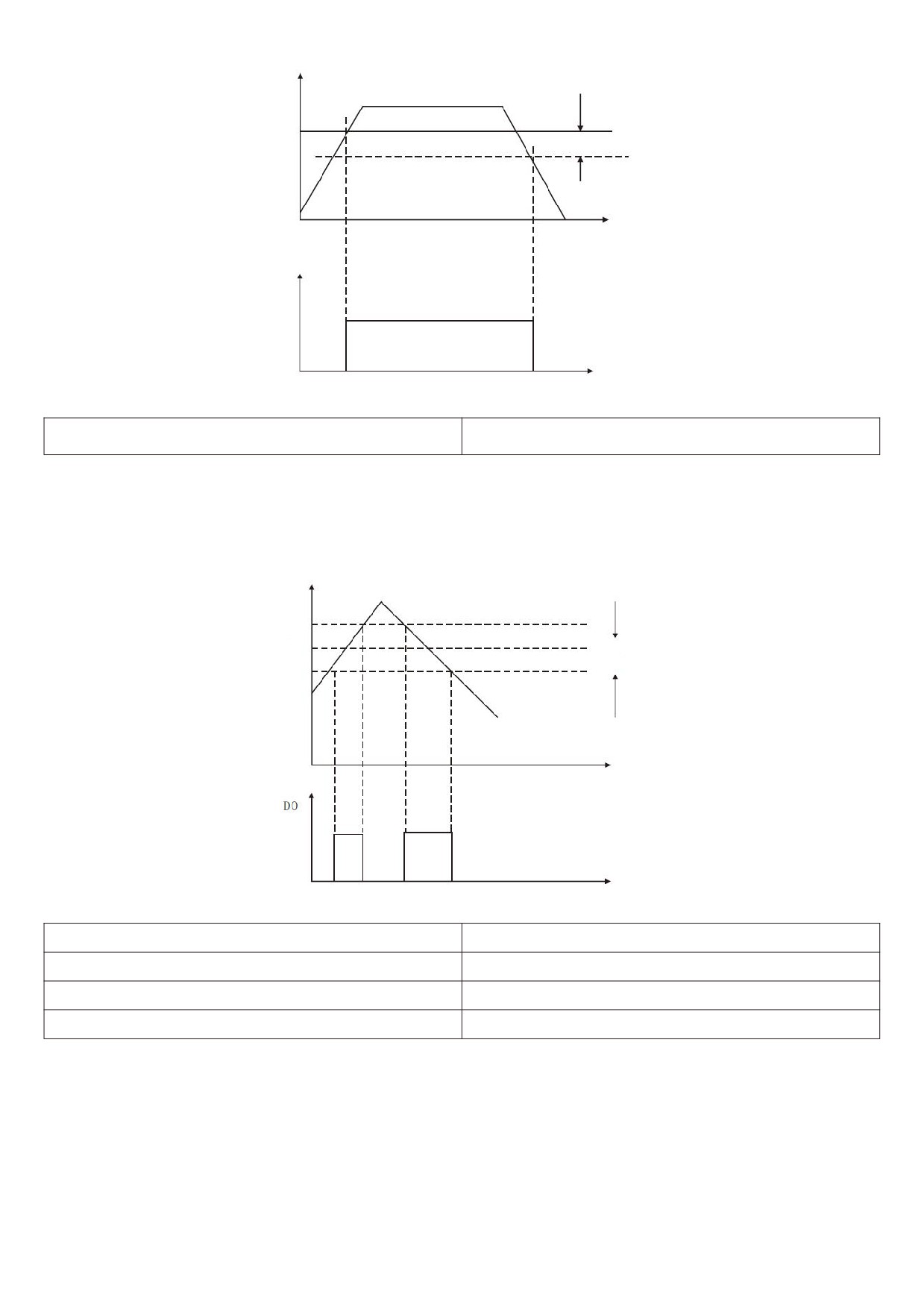
Output voltage
FDT lag
Time
Detected
signal
Figure 5 - 09 FDT level diagram
F4 - 28 frequencies reaches detection width
0.00 ~ 100 % (maximum frequency) [0.0 %]
When the operating frequency of the frequency inverter is within a certain range of the target frequency, the
multi-function (04) DO of the frequency inverter outputs an on signal.
This parameter is used to set the detection range of frequency arrival and this parameter is a percentage of the
maximum frequency. Figure 5 - 10 is a schematic diagram of frequency arrival.
Output voltage
Setup frequency
Detection width
Figure 5 - 10 schematic diagram of frequency arrival detection amplitude
F4-29 random arrival frequency detection value 1
0.00 Hz ~ maximum frequency [ 50.00 Hz ]
F4-30 random arrival frequency detection width 1
0.0%~100.0% [0.0%]
F4-31 random arrival frequency detection value 2
0.00 Hz ~ maximum frequency [ 50.00 Hz ]
F4-32 random arrival frequency detection width 2
0.0%~100.0% [0.0%]
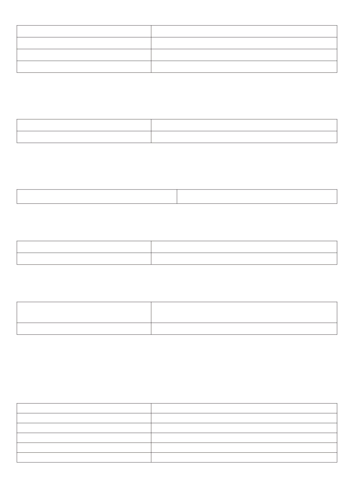
When the output frequency of the frequency inverter is within the positive and negative detection range of any
frequency detection value, the multi-function DO (No. 26 and No. 27) outputs on signal
HV610 provides two groups of random arrival frequency detection parameters, setting frequency values and
frequency detection ranges respectively. Figure 5 - 11 is a schematic diagram of this function.
79
F4-33 arbitrarily reaching current 1
0.0 % ~ 300.0 % ( rated current of motor ) [ 100.0 % ]
F4-34 the width of current 1 is arbitrarily reach
0.0 % ~ 300.0 % ( rated current of motor ) [ 0.0% ]
F4-35 arbitrarily reaching current 2
0.0 % ~ 300.0 % ( rated current of motor ) [ 100.0% ]
F4-36 the width of current 2 is arbitrarily reach
0.0 % ~ 300.0 % ( rated current of motor ) [ 0.0% ]
When the output current of the frequency inverter is set within the positive and negative detection width of any
arriving current, the multi-function DO (No. 28 and No. 29) of the frequency inverter outputs on signal.
HV610 provides two groups of random arrival currents and detection width parameters. The detection principle
is similar to F4 - 29 ~ F4 - 32.
F4 - 37 AI1 input voltage protection value lower
0.00V~F4-38 [3.1V]
limi-
F4
38 upper limit of AI1 input voltage
F4-37~10.00V [6.8V]
protection value
When the analog input value of AI1 is greater than F4 - 38, or AI1 input value is less than F4 - 37, the
multi-function DO (31) of the frequency changer outputs an “AI1 input overrun" ON signal to indicate whether the
input voltage of AI1 is within the set range.
F4 - 39 module temperatures reached
0 ~ 100 [75°C]
When the frequency inverter radiator temperature reaches the temperature, the multi-function DO of the
frequency inverter outputs the “module temperature reaches" ON message
F4 - 40 zero current detection level
0.0 % ~ 300.0 % ( rated current of motor ) [ 5.0% ]
F4 - 41 zero current detection delay time
0.00s~600.00s [0.10s]
When the output current of the frequency inverter is less than or equal to the zero current detection level and the
duration exceeds the zero current detection delay time, the frequency inverter multifunction ( No. 34 ) DO outputs ON
signal.
0.0 % ( no detection );
F4 - 42 output current overrun value
0.1% ~ 300.0 % ( rated current of motor ) [ 200.0% ]
F4 - 43 output current overrun detection delay
0.00s~600.00s [0.00s]
time
When the output current of the frequency inverter is greater than or exceeds the limit detection point and the
duration exceeds the software over current point detection delay, the frequency inverter multifunction (No. 36) DO
outputs on signal.
F5 Group input terminals
F5 - 00 XI terminal function selection
0~60 [1]
F5 - 01x2 terminal function selection
0~60 [2]
F5 - 02 x3 terminal function selection
0~60 [9]
F5 - 03x4 terminal function selection
0~60 [12]
F5 - 04x5 terminal function selection
0~60 [13]
F5 - 05x6 terminal function selection
0~60 [14]
80
F5 - 06 X7 terminals function selection
0 ~ 60 [8]
These parameters are used to set the functions of the digital multi-function input terminals and the functions that
can be selected are shown in the following table:
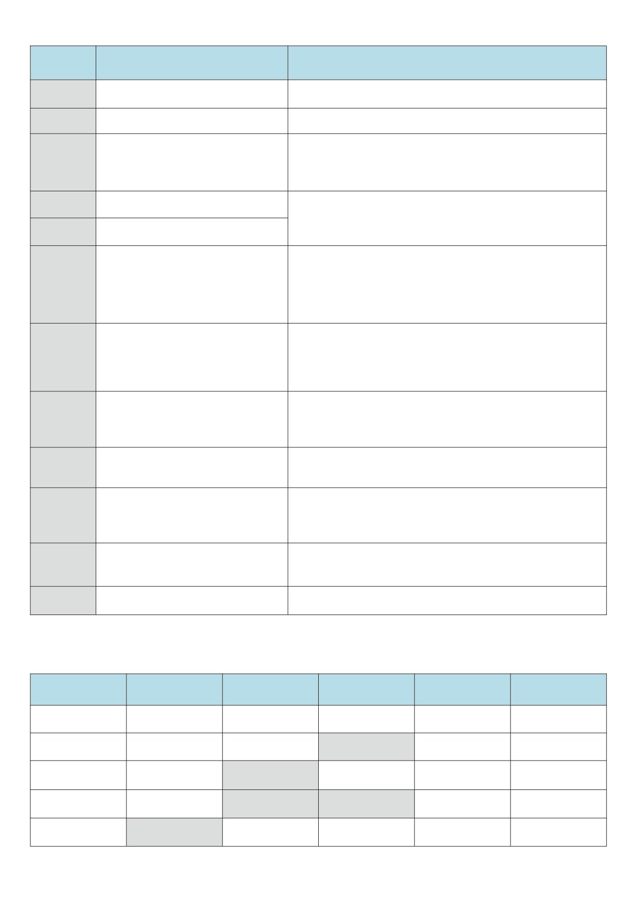
Setting
Functionalities
Description
value
The unused terminals can be set to “no function" to prevent
0
Nonfunctional
misoperation.
1
Forward run ( FWD )
The forward rotation and reverse rotation of the frequency
inverter are controlled through external terminals.
2
Reverse run (REV)
Through this terminal, it is determined that the frequency
inverter operation mode is a three-wire control mode. Please
3
Three - wire operation control
refer to the description of function code F5 - 11 (“terminal
command method”) for details.
FJOG is JOG forward rotation, RJOG is JOG reverse rotation.
4
Forward JOG(FJOG)
Refer to the function code for JOG operation frequency and
JOG acceleration / deceleration time description of F6 - 13, F6
5
Reverse JOG(RJOG)
- 14, F6 - 15.
6
Terminal UP
The increment and decrement instructions of the frequency are
modified when the frequency is given by the external terminal.
When the frequency source is set to digital setting, the setting
7
Terminal DOWN
frequency of the section can be adjusted up and down.
The frequency inverter blocks the output. At this time, the stop
8
Free parking
process of the motor is not controlled by the frequency
changer.
The function of using terminals to reset faults. Same function
9
Fault reset(RESET)
as reset key on keyboard. This function can be used to reset
the remote fault barrier.
The frequency inverter decelerates and stops, but all operating
parameters are memorized. Such as PLC parameters, swing
10
Suspension of operation
frequency parameters and PID parameters. After this terminal
signal disappears, the frequency inverter returns to the
operating state before parking.
When the signal is sent to the frequency inverter, the frequency
11
External fault normally open input
inverter reports the failure ETF.
12
Multi-segment command terminal
1
13
Multi-segment command terminal
2
The speed of 16 segments can be realized through 16 States
14
Multi-segment command terminal
3
of the four terminals. See attached table 1 for details.
15
Multi-segment command terminal
4
Acceleration and deceleration time
16
Through the four States of the two terminals, the choice
selection terminal 1
between the four acceleration and deceleration times can be
Acceleration and deceleration time
17
realized, see table 2 for details.
selection terminal 2
Used to switch and select different frequency sources.
According to the setting of the frequency source selection
18
Frequency source switching
function code (F0 - 32); this terminal is used to switch between
two frequency sources when switching between two frequency
sources is set as the frequency source.
When the frequency is given as a digital frequency, this
UP/DOWN setting cleared ( terminal,
terminal can clear the frequency value changed by the terminal
19
keyboard )
UP/DOWN or the keyboard UP/DOWN to restore the given
frequency to the value set in F0 - 09.
81
Setting
Functionalities
Description
value
When the command source is set to terminal control (F0 - 02 =
1), this terminal can switch between terminal control and
Control command switching terminal
keyboard control.
20
1
When the command source is set to communication control (F0
- 02 = 2), this terminal can switch between communication
control and keyboard control.
Ensure that the frequency inverter is not affected by external
Acceleration and deceleration
21
signals (except shutdown command) and maintain the current
prohibition
output frequency.
The PID is temporarily disabled; the frequency inverter
22
PID pause
maintains the current output frequency and no longer performs
PID adjustment of the frequency source.
The PLC is suspended during the execution process. When the
23
PLC status reset
PLC runs again, the frequency inverter can be restored to the
initial state of the simple PLC through this terminal.
The frequency inverter outputs at the center frequency. The
24
The pendulum frequency suspended
frequency swing function is suspended.
25
Counter input
Input terminal of counting pulse.
26
Counter reset
The counter status is cleared.
27
Length count input
Input terminal for length count.
28
Length reset
Length zero clearing
It is forbidden for the frequency inverter to carry out torque
29
Torque control prohibited
control, and the frequency inverter enters the speed control
mode.
PULSE(Pulse) frequency input
30
X5 functions as a pulse input terminal.
( valid only for X5 )
31
Reserve
Reserve
When this terminal is active, the frequency inverter switches
32
Immediate DC braking
directly to the DC braking state
When the normally closed signal of an external fault is sent to
33
External fault normally closed input
the frequency inverter, the frequency inverter reports the fault
ETF and stops the operation.
If this function is set to active, when the frequency changes, the
34
Frequency modification prohibition
frequency inverter will not respond to the frequency change
until the terminal status is active.
The direction of PID action is
When this terminal is active, the direction of PID action is
35
reversed
opposite to the direction set by FA - 03
When the keyboard is controlled, this terminal can be used to
36
External parking terminal 1
stop the frequency inverter, which is equivalent to the function
of the STOP key on the keyboard.
Used for switching between terminal control and
Control command switching terminal
communication control. If the source is selected as terminal
37
2
control, the system will switch to communication control when
the terminal is active; on the contrary, it is also the opposite.
When this terminal is valid, the integral adjustment function of
38
PID integral suspended
the PID is suspended, but the proportional adjustment and
differential adjustment functions of the PID are still valid.
Frequency source X switches to
If the terminal is valid, the frequency source X is replaced by a
39
preset frequency
preset frequency ( F0 - 09 )
Frequency source Y switches to
This terminal is valid, then the frequency source Y is replaced
40
preset frequency
by a preset frequency ( F0 - 09 )
82
Setting
Functionalities
Description
value
2 sets of motor parameters can be switched through the 2
41
Motor selection terminal 1
states of terminals, see table 3 for details.
42
Reserve
Reserve
When the PID parameter switching condition is X terminal (FA -
18 = 1), when the terminal is invalid, the PID parameters are FA
43
PID parameter switching
- 05 ~ FA - 07; When the terminal is valid, FA - 15 ~ FA - 17 will
be used.
44
User - defined fault 1
When user-defined faults 1 and 2 are valid, the frequency
inverter alarms UEF1 and UEF2 respectively.
45
User - defined fault 2
It causes the inverter to switch between torque control and
speed control modes. When this terminal is invalid, the inverter
Speed control / torque control
operates in the mode defined by F7 - 00 (speed / torque control
46
switching
mode), and when this terminal is valid, it switches to another
mode. During operation, switching can be carried out through
terminals, which will take effect immediately after switching
When the terminal is valid, the frequency inverter stops at the
fastest speed, and the current is at the upper limit set during
47
Emergency stop
the stop. This function is used to meet the requirement that the
frequency inverter needs to be shut down as soon as possible
when the system is in an emergency.
Under any control mode (panel control, terminal control, and
communication control), this terminal can be used to slow
48
External parking terminal 2
down and stop the frequency inverter. The deceleration time at
this time is fixed at deceleration time 4.
When this terminal is active, the frequency inverter will first
49
Deceleration DC brake
slow down to the stop DC brake starting frequency and then
switch to the DC brake state.
When this terminal is valid, the timing time of this operation of
the frequency inverter is cleared. This function needs to be
50
This run time is cleared
used in conjunction with the timing operation (F8 - 04) and the
arrival of this operation time (F8 - 07).
For switching between two-wire and three-wire control. If F5 -
51
Two - wire / three-wire switching
11 is two-wire type 1, switch to three-wire type 1 when the
terminal function is valid. And so on.
This terminal is valid, and frequency inverter reversal is
52
Prohibition of reversal
prohibited. Same function as F0 - 04.
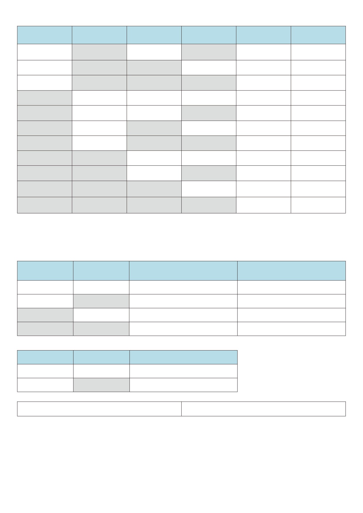
Four multi-segment command terminals can be combined into 16 States, each of which corresponds to 16
command settings. Specific as shown in table 1:
Attached table 1 multi-paragraph instruction function description
Corresponding
K4
K3
K2
K1
Command setting
parameter
Multi - segment
OFF
OFF
OFF
OFF
FC-00
instruction 0
Multi - segment
OFF
OFF
OFF
ON
FC-01
instruction 1
Multi - segment
OFF
OFF
ON
OFF
FC-02
instruction 2
Multi - segment
OFF
OFF
ON
ON
FC-03
instruction 3
Multi - segment
OFF
ON
OFF
OFF
FC-04
instruction 4
83
Corresponding
K4
K3
K2
K1
Command setting
parameter
Multi - segment
OFF
ON
OFF
ON
FC-05
instruction 5
Multi - segment
OFF
ON
ON
OFF
FC-06
instruction 6
Multi - segment
OFF
ON
ON
ON
FC-07
instruction 7
Multi - segment
ON
OFF
OFF
OFF
FC-08
instruction 8
Multi - segment
ON
OFF
OFF
ON
FC-09
instruction 9
Multi - segment
ON
OFF
ON
OFF
FC-10
instruction 10
Multi - segment
ON
OFF
ON
ON
FC-11
instruction 11
Multi - segment
ON
ON
OFF
OFF
FC-12
instruction 12
Multi - segment
ON
ON
OFF
ON
FC-13
instruction 13
Multi - segment
ON
ON
ON
OFF
FC-14
instruction 14
Multi - segment
ON
ON
ON
ON
FC-15
instruction 15
When the frequency source is selected as multi-segment speed, 100.0
% of the function codes FC - 00 ~ FC -
15
correspond to the maximum frequency F0 - 16. In addition to being a multi-stage speed function, multi-stage
instructions can also be used as a given source of PID or as a voltage source for VF separation control, etc. to meet
the need of switching between different given values.
Table 2 description of terminal function for acceleration and deceleration time selection
Selection of acceleration or
Terminal 2
Terminal 1
Corresponding parameter
deceleration time
OFF
OFF
Acceleration time 1
F0-10, F0-11
OFF
ON
Acceleration time 2
F6-17,F6-18
ON
OFF
Acceleration time 3
F6-19,F6-20
ON
ON
Acceleration time 4
F6-21,F6-22
Attached table 3 motor selection terminal function description
Terminal 2
Terminal 1
Motor selection
OFF
OFF
Motor 1
OFF
ON
Motor 2
F5 - 10 X input terminal filtering time
0.000s~1.000s [0.010s]
Set software filtering time for X terminal status. If the input terminal is easily interfered and causes misoperation in
use, this parameter can be increased to enhance the anti-interference ability.
However, the increase in the filtering time will cause the response of the X terminal to slow down.
84
F5 - 11 terminal command mode
0~3 [0]
This parameter defines four different ways to control the operation of the frequency inverter through external
terminals.
Note: for convenience of explanation, the X1, X2 and X3 terminals among the X1 - X7 multifunction input
terminals are randomly selected as external terminals. That is, the functions of X1, X2 and X3 terminals are
selected by setting the values of F5 - 00 to F5 - 02. See the setting range of F5 - 00 to F5 - 06 for detailed
function definition.
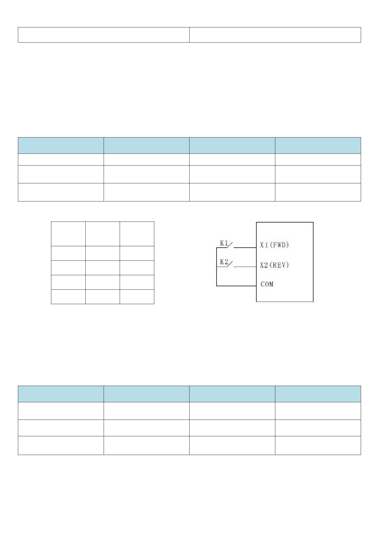
0: two-wire mode 1: this mode is the most commonly used two-wire mode. The forward and reverse rotation of
the motor is determined by terminals x1 and x2.
The function code is set as follows:
Function code
Name
Setting value
Functional description
F5-11
Terminal command mode
0
Two - wire type 1
X1 terminal function
F5-00
1
Forward run ( FWD )
selection
X2 terminal function
F5-01
2
Reverse run (REV)
selection
Operating
K1
K2
instructions
1
0
Forward
0
1
Reversal
1
1
Stop
0
0
Stop
Figure 5 - 12 two-wire modes 1
As shown in the above figure, in this control mode, k1 is closed and the frequency inverter is running forward. K2
closes and reverses, k1 and k2 close or open at the same time, and the frequency inverter stops running.
1: two-wire mode 2: with this mode, the x1 terminal function is the operation enable terminal, while the x2 terminal
function determines the direction of operation.
The function code is set as follows:
Function code
Name
Setting value
Functional description
F5-11
Terminal command mode
1
Two - wire type 2
X1 terminal function
F5-00
1
Operation enable
selection
X2 terminal function
Positive and negative
F5-01
2
selection
direction of operation
85
Operating
K1
K2
instructions
1
0
Forward
1
1
Reversal
0
1
Stop
0
0
Stop
Figure 5 - 12 two-wire modes 2
As shown in the above figure, in this control mode, k2 opens the frequency inverter for forward rotation and k2
closes the frequency inverter for reverse rotation in the k1 closed state. K1 is disconnected and the frequency
inverter stops running.
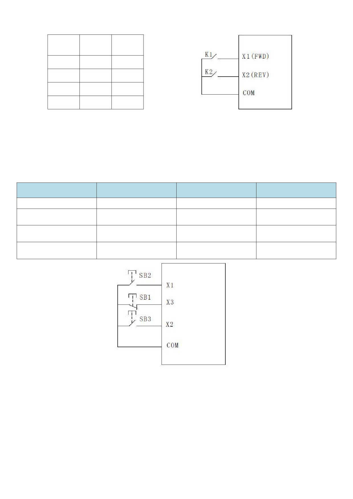
2: Three-wire control mode 1: this mode X3 is an enable terminal, and the directions are controlled by x1 and X2
respectively.
The function code is set as follows:
Function code
Name
Setting value
Functional description
F5-11
Terminal command mode
2
Three wire type 1
X1 terminal function
F5-00
1
Forward run ( FWD )
selection
X2 terminal function
F5-01
2
Reverse run (REV)
selection
X3 terminal function
Three - wire operation
F5-02
3
selection
control
Figure 5 - 14 three-wire control modes 1
As shown in the above figure, the control mode is in the closed state of SB1 button, press SB2 button to rotate
the frequency inverter forward, press SB3 button to rotate the frequency inverter reversely, and the sb1 button opens
and the frequency inverter stops at the moment. During normal start-up and operation, it is necessary to keep the
SB1 button closed. The commands of SB2 and SB3 buttons will take effect at the closing action edge and the
operating state of the frequency inverter will be subject to the last key action of the three buttons.
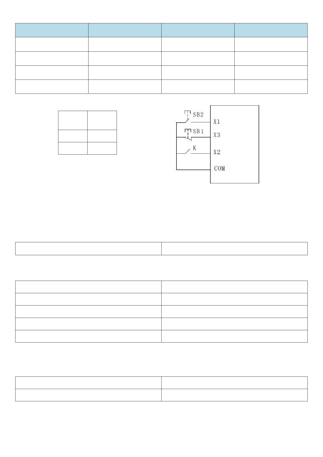
3.3 - wire control mode 2:X3 in this mode is the enable terminal, the operation command is given by X1, and the
direction is given by X1 the status of X2 is determined.
The function code is set as follows
86
Function code
Name
Setting value
Functional description
F5-11
Terminal command mode
3
Three wire type 2
X1 terminal function
F5-00
1
Operation enable
selection
X2 terminal function
Positive and negative
F5-01
2
selection
direction of operation
X3 terminal function
Three - wire operation
F5-02
3
selection
control
Direction of
K
Operational
movement
0
Forward
Stop
1
Reversal
Reversal
Figure 5 - 15 three-wire control modes 2
As shown in the figure above, the control mode is under the closed state of SB1 button, press the SB2 button
converter to run, K turns off the inverter and K closes the inverter. SB1 button turns off and the frequency inverter
stops immediately. During normal start-up and operation, it is necessary to keep the SB1 button closed, and the SB2
button command will take effect at the edge of the closing action.
F5 - 12 terminal UP/DOWN change rate
0.01Hz/s~65.535Hz/s [1.00Hz/s]
When setting terminal UP/DOWN to adjust the set frequency, the speed of frequency changes, that is, the
amount of frequency change per second.
F5 - 13 PULSE minimum input
0.00kHz~F5-15 [0.00HZ]
F5 - 14 PULSE minimum input corresponding settings
-100.0%~100.0% [0.00HZ]
F5 - 15 PULSE maximum input
F5-13~50.00KHZ [50.00KHZ]
F5 - 16 PULSE maximum input corresponding settings
-100.0%~100.0% [100.0%]
F5 - 17 PULSE filter time
0.00s~10.00s [0.01s]
This set of function codes is used to set the relationship between X5 pulse frequency and corresponding
settings.
The pulse frequency can only be input to the frequency inverter through X5 channel.
F5 - 18 X1 delay time
0.0s~3600.0s [0.00S]
F5 - 19 X2 delay time
0.0s~3600.0s [0.00S]
87
F5 - 20 X3 delay time
0.0s~3600.0s [0.00S]
Used to set the delay time for the change of X terminal state by the frequency inverter at present, only X1, X2,
X3 have the function of setting the delay time.
F5 - 21 X terminal active mode selection 1
00000~11111 [00000]
Bit: x1 terminal logic set to
0: positive logic
1. Inverse logic
10 bits: X2 terminal valid state setting (0 ~ 1, ditto)
100 bits: X3 terminal valid state setting (0 ~ 1, ditto)
1000 bits: X4 terminal valid state setting (0 ~ 1, ditto)
10,000 bits: X5 terminal valid state setting (0 ~ 1, ditto)
When positive logic is selected, the corresponding X terminal is valid when connected to com, and
disconnection is invalid.
If it is selected as anti-logic valid, the corresponding X terminal will not be valid if it is connected to com, and the
disconnection will be valid.
F5 - 22 X terminal active mode selection 2
00000~11111 [00000]
Bit: X6 terminal logic set to 0: positive logic
1: inverse logic
10 bits: x7 terminal active state setting (0 ~ 1, same as above)
When positive logic is selected, the corresponding X terminal is valid when connected to com, and
disconnection is invalid.
If it is selected as anti-logic valid, the corresponding X terminal will not be valid if it is connected to com, and the
disconnection will be valid.
F5 - 24 AI curve 1 min input
0.00V~F5-26 [0.00V]
F5 - 25 AI curve 1 minimum input corresponding settings
-100.0%~100.0% [0.0%]
F5 - 26 AI curve 1 maximum input
F5-24~10.00V [10.00V]
F5 - 27 AI curve 1 maximum input corresponding settings
-100.0%~100.0% [100.0%]
F5 - 28 AI1 filtering time
0.00s~10.00s [0.10s]
The above function code is used to set the relationship between the analog input voltage and the set value it
represents.
When the voltage of analog input is greater than the set “maximum input" (F5 - 26), the analog voltage is calculated
according to “maximum input". Similarly, when the analog input voltage is less than the set " minimum input" ( F5 -
24 ), it is calculated as the minimum input or 0.0 % based on the setting of " AI is lower than the minimum input
setting selection" ( F5 - 40 ).
When the analog input is a current input, 1ma current is equivalent to 0.5v voltage.
AI1 input filtering time is used to set the software filtering time of AI1. When the analog quantity in the field is
easily interfered, please increase the filtering time to stabilize the detected analog quantity. However, the larger the
filtering time is, the slower the response speed to the analog quantity detection will be. How to set it needs to be
weighed according to the actual application situation
In different applications, the meaning of the nominal value corresponding to 100.0 % set by simulation is
different. Please refer to the description of each application section for details.
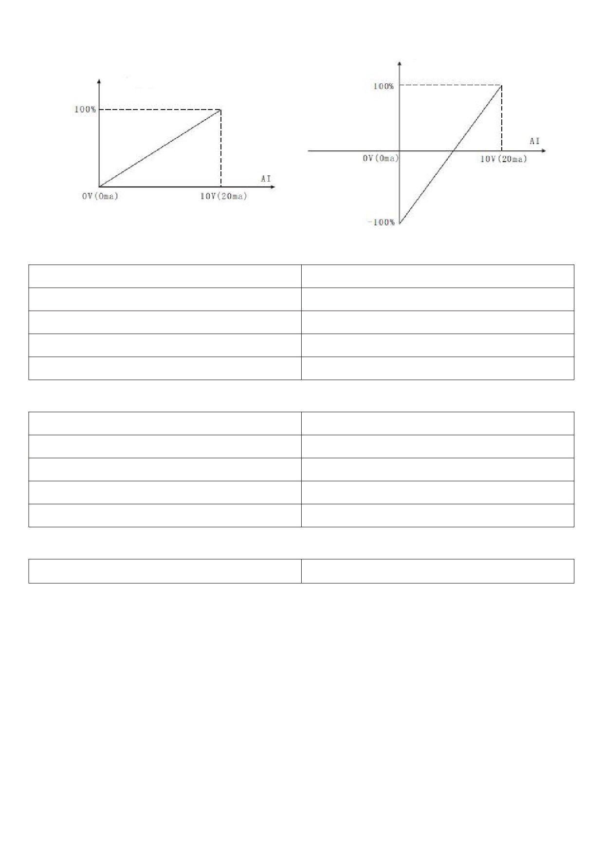
The following illustrations show two typical settings:
88
Correspondence setting
Correspondence setting
(Frequency / torque)
(Frequency / torque)
Figure 5 - 16 simulates the correspondence between a given value and a set value
F5 - 29 AI curve 2 minimum input
0.00V~F5-31 [0.00V]
F5 - 30 AI curve 2 minimum input corresponding settings
-100.0%~100.0% [0.0%]
F5 - 31 AI curve 2 maximum input
F5-29~10.00V [10.00V]
F5 - 32 AI curve 2 maximum input corresponding settings
-100.0%~100.0% [100.0%]
F5 - 33 AI2 filtering time
0.00s~10.00s [0.10s]
For the function and usage of curve 2, please refer to the description of curve 1.
F5 - 34 AI curve 3 minimum input
0.00V~F5-36 [0.00V]
F5 - 35 AI curve 3 minimum input corresponding settings
-100.0%~100.0% [0.0%]
F5 - 36 AI curve 3 maximum input
F5-34~10.00V [10.00V]
F5 - 37 AI curve 3 maximum input corresponding settings
-100.0%~100.0% [100.0%]
F5 - 38 AI3 filtering time
0.00s~10.00s [0.10s]
For the function and usage of curve 3, please refer to the description of curve 1.
F5 - 39 AI curve selection
111~555 [321]
Bit: curve selection corresponding to AI1
1: Curve 1 (2 - point curve, see F5 - 24 ~ F5 - 27)
2: Curve 2 (2 - point curve, see F5 - 29 ~ F5 - 32)
3: Curve 3 (2 - point curve, see F5 - 34 ~ F5 - 37)
4: Curve 4 (4 - point curve, see F5 - 41 ~ F5 - 48)
5: Curve 5 (4 - point curve, see F5 - 49 ~ F5 - 56)
10 bits: the curve corresponding to AI2 are selected to be
1 - 5 and are the same as the individual bits.
100 bits: the curves corresponding to AI3 are selected to be
1 - 5 and are the same as the individual bits.
Notes:
The individual bit, ten bits and hundred bits of the function code are respectively used for selection, and analog
input AI1, AI2 and AI3 correspond to the set curves. 3 analog quantity input can select any one of the five curves.
Curve 1, curve 2, and curve 3 are all 2 - Point curve, while curve 4 and curve 5 are both 4 - point curves.
89

F5 - 40 AI is lower than the minimum input setting
000~111 [000]
selection
Bit: AI1 is lower than the minimum input setting selection
0: corresponds to minimum input settings.
1:0.0%
If it is less than the minimum input, 0.0 % is considered as input.
10 bits: AI2 is lower than the minimum input setting and the definitions of
0~1 is the same as the individual bits.
10 bits: AI3 is lower than the minimum input setting and the definitions of
0~1 is the same as the individual bits.
This function code is used for setting, when the voltage of analog quantity input is less than the set “minimum
input", how to determine the setting corresponding to analog quantity input.
The individual, ten and hundred bits of the function code correspond to analog quantity inputs AI1, AI2 and AI3,
respectively.
If
0 is selected, when the AI input is lower than the “minimum input", the corresponding setting of the analog
quantity is the function code.
Determined curve “minimum input corresponding settings" (F5 - 25, F5 - 30, F5 - 35). If 1 is selected, when the
AI input is lower than the minimum input, the corresponding setting of the analog quantity is
0.0
%.
F5 - 41 AI curve 4 minimum input
0.00V~F5-43 [0.00V]
F5 - 42 AI curve 4 minimum input corresponding settings
-100.0%~100.0% [0.0%]
F5 - 43 AI curve 4 inflection point 1 input
F5-41~F5-45V [3.00V]
F5 - 44 AI curve 4 inflection point 1 input corresponding
-100.0%~100.0% [30.0%]
settings
F5 - 45 AI curve 4 inflection point 2 input
F5-43~F5-47 [6.00V]
F5 - 46 AI curve 4 inflection point 2 input corresponding
-100.0%~100.0% [60.0%]
settings
F5 - 47 AI curve 4 maximum input
F5-29~10.00V [10.00V]
F5 - 48 AI curve 4 maximum input corresponding settings
-100.0%~100.0% [100.0%]
F5 - 49 AI curve 5 min input
0.00V~F5-51 [0.00V]
F5 - 50 AI curve 5 minimum input corresponding settings
-100.0%~100.0% [0.0%]
F5 - 51 AI curve 5 inflection point 1 input
F5-49~F5-53V [3.00V]
F5 - 52 AI curve 5 inflection point 1 input corresponding
-100.0%~100.0% [30.0%]
settings
F5 - 53 AI curve 5 inflection point 2 input
F5-51~F5-55 [6.00V]
90
F5-54 AI curve 5 inflection point 2 input corresponding
-100.0%~100.0% 【60.0%】
settings
F5-55 AI curve 5 maximum input
F5-53~10.00V 【10.00V】
F5-56 AI curve 5 maximum input corresponding settings
-100.0%~100.0% 【100.0%】
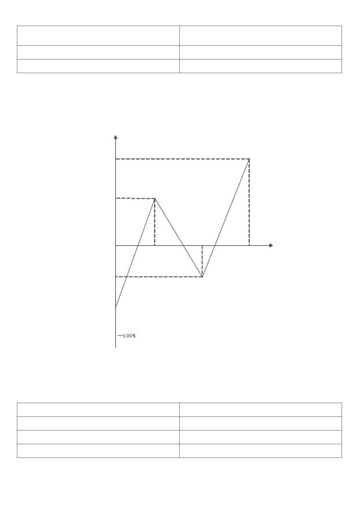
The functions of curve 4 and curve 5 are similar to those of curve 1 to curve 3, but curve 1 to curve 3 are 2 - point
straight lines, while curve 4 and curve 5 are 4 - point curves, which can realize more flexible correspondence. Figs. 5
- 17 are schematic diagrams of curves 4 to 5, taking curve 4 as an example.
Analog input corresponding
set quantity (100 %)
Maximum input settings
corresponding to
Inflection point 1
corresponding setting F5-44
Inflection point 2
input
OV/0mA
Inflection point 1 input
AI voltage input (10V)
Inflection point 2 corresponds
to setting F5 - 46
AI minimum input setting
F5 - 42
Figure 5 - 17 schematic diagram of 4 - point curve
Notes:
When setting curve 4 and curve 5, you should pay attention to the following conditions: minimum input voltage of
curve < inflection point 1 voltage < Inflection point 2 voltage < maximum voltage
F5-65 AI1 sets jumping point
-100.0%~100.0% 【0.0%】
F5-66 AI1 sets jump amplitude
0.0% - 100.0% 【0.5%】
F5-67 AI2 sets jumping point
-100.0%~100.0% 【0.0%】
F5-68 AI2 sets jump amplitude
0.0% - 100.0% 【0.5%】
91
F5-69 AI3 sets jumping point
-100.0%~100.0% 【0.0%】
F5-70 AI3 sets jump amplitude
0.0% - 100.0% 【0.5%】
Analog quantity inputs AI1 to AI3 have the function of setting value jump. The skip function refers to setting the
analog quantity corresponding to changes in the upper and lower sections of the skip point.
The value is fixed to the value of the jumping point.
Example:
The voltage of analog quantity input AI1 fluctuates up and down 5.00V, ranging from 4.90V to 5.10V. the
minimum input 0.00 V of AI1 corresponds to 0.0 % and the maximum input 10.00V corresponds to 100. %. And then
the detected AI1 corresponds to a fluctuation of 49.0 % ~ 51.0 %.
Setting AI1 set jumping point F5 - 65 to 50.0 % and setting AI1 set jumping amplitude F5 - 66 to 1.0 %, the
corresponding setting of the obtained AI1 input after the jump function processing is fixed to 50.0 %, AI1 is converted
into a stable input and the fluctuation is eliminated.
F6 Group start-stop control
F6 - 00 starting operation mode
0~2 [0]
0: direct starting
If the starting DC braking time is set to 0, the frequency inverter will start operating from the starting frequency.
If the starting DC braking time is not 0, DC braking will be performed first, and then operation will start from the
starting frequency. Suitable for small inertia load, where the motor may rotate during start - up
1: speed tracking and restarting
The frequency inverter first judges the speed and direction of the motor, then starts at the tracked frequency of
the motor, and during rotation the motor starts smoothly and without impact. It is suitable for the restart of large
inertia load with instantaneous power failure. In order to ensure the performance of speed tracking and restart, it is
necessary to accurately set the f1 parameters of the motor.
2: The pre-excitation starting of the asynchronous machine
Is only valid for the asynchronous motor, which is used to establish the magnetic field before the motor runs.
Refer to the description of function codes F6 - 05 and F6 - 06 for pre-excitation current and pre-excitation time.
If the pre-excitation time is set to 0, the frequency inverter cancels the pre-excitation process and starts from the
starting frequency. If the pre-excitation time is not 0, the motor can be pre-excited before starting, which can improve
the dynamic response performance of the motor.
F6 - 01 speed tracking method
0~2 [0]
In order to complete the speed tracking process in the shortest time, select the way that the frequency inverter
tracks the motor speed:
0: starting from shutdown frequency
This method is usually used to track down from the frequency of power failure.
1: starting from zero speed
Track up from zero frequency, and use it in case of power failure for a long time before starting.
2: starting from the maximum frequency
Track down from the maximum frequency and use the general power generating load.
92
F6 - 02 rotational speed tracking speed
0~100 [20]
When speed tracking is restarted, select the speed of speed tracking.
The larger the parameter, the faster the tracking speed However, setting too large may lead to unreliable
tracking results.
F6 - 03 startup frequency
0.00Hz~10.00Hz 【0.00Hz】
F6 - 04 startup frequency hold time
0.0s~100s 【0.0s】
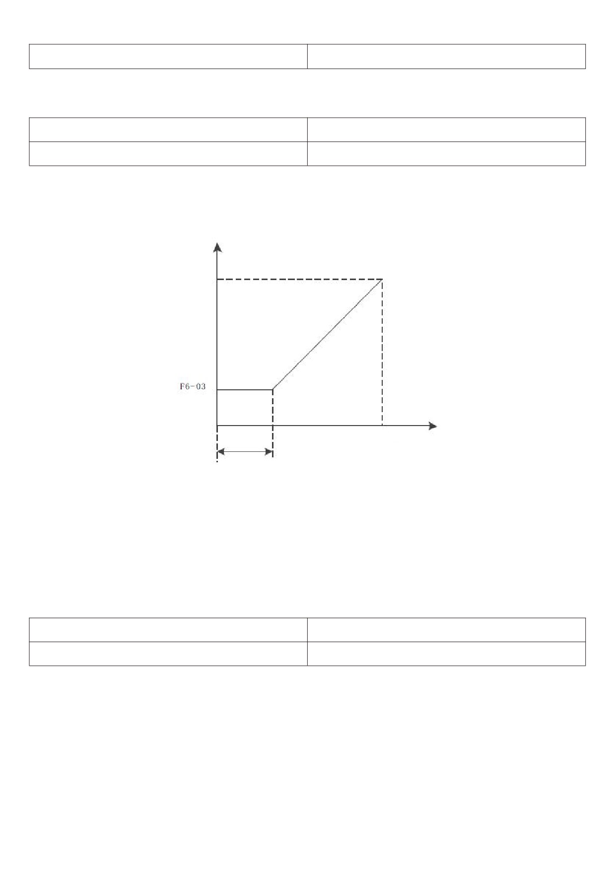
In order to ensure the motor torque during starting, please set the appropriate starting frequency. In order to fully
establish magnetic flux when starting the motor, it is necessary to keep the starting frequency for a certain period of
time.
The relationship between starting frequency and starting time is shown in figure 5 - 18.
Frequency
Time
Figure 5 - 18 startup frequency and startup time
Notes:
The starting frequency F6 - 03 is not limited by the lower limit frequency.
When the set target frequency is less than the starting frequency, and the frequency inverter will not start and
will be in standby mode.
During forward and reverse switching, the start frequency holding time does not work.
The startup frequency holding time is not included in the acceleration time, but is included in the operation time
of the simple PLC.
F6-05 start DC brake current / pre-excitation current
0%~100% 【0%】
F6-06 start DC brake time / pre - excitation time
0.0s~100.0s 【0.0s】
Start the direct current brake, which is usually used to stop the running motor before starting. The pre-excitation
is used to set up a magnetic field before starting the asynchronous motor to improve the response speed.
If it is valid when the startup mode is direct startup at this time, the frequency inverter performs direct current
braking according to the set starting direct current braking current, and starts to run after the starting direct current
braking time. If the DC braking time is set to 0, it will be started directly without direct current braking.
If the starting mode is asynchronous machine pre-excitation starting, the frequency inverter first establishes a
magnetic field in advance according to the set pre-excitation current, and then starts to run after the set
pre-excitation time. If the pre-excitation time is set to
0, it will be started directly without going through the
pre-excitation process.
93
F6-07 stop DC brake starting frequency
0.00 Hz ~ maximum frequency [ 0.00 Hz ]
F6-08 stop DC brake waiting time
0.0s~36.0s 【0.0s】
F6-09 stop DC brake current
0%~100% 【0%】
F6-10 stop DC braking time
0.0s~36.0s 【0.0s】
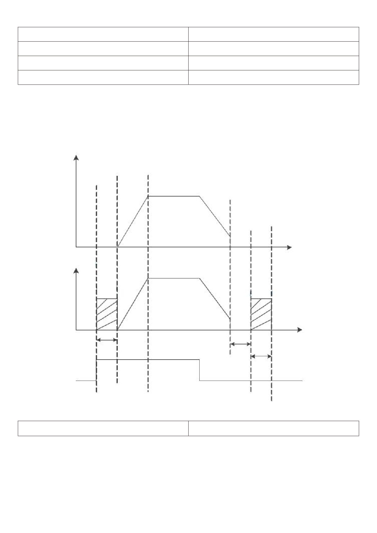
Stop DC brake starting frequency: during deceleration and stop, when the operating frequency drops to this
frequency, the DC brake process starts.
Stop DC brake waiting time: after the operating frequency is reduced to the stop DC brake starting frequency,
the frequency inverter stops output for a period of time before starting the DC brake process. It is used to prevent
over-current and other faults that may be caused by starting DC braking at higher speeds
Output frequency
Time
Time
Output voltage
Starting DC
Parking DC brake quantity
momentum control
Time
Starting braking time
Brake waiting time
Parking brake time
Run command
Figure 5 - 19 schematic diagram of DC braking
F6 - 11 brake usage rate
0%~100% 【100%】
Valid only for frequency inverter with built-in brake unit
It is used to adjust the duty ratio of the moving unit and if the brake usage rate is high, the duty ratio of the brake
unit is high and the brake effect is strong, but the inverter bus voltage fluctuates greatly during braking.
Notes:
The setting of this function code should take into account the resistance and power of the braking resistor.
94
F6-13 JOG frequency
0.00 Hz ~ maximum frequency [ 2.00 Hz ]
F6-14 JOG acceleration time
0.0s~6500.0s 【20.0s】
F6-15 JOG deceleration time
0.0s~6500.0s 【20.0s】
The given frequency and acceleration / deceleration time of the frequency inverter during define JOG.
During JOG operation, the starting mode is fixed as direct starting mode and the stopping mode is fixed as
deceleration stopping mode.
F6 -16 terminal JOG takes precedence
0~1 【0】
This parameter is used to set whether the terminal jog function has the highest priority.
When the terminal JOG takes precedence, if the terminal JOG command appears during operation, the
frequency inverter will switch to the terminal point running status
F6 - 17 acceleration time 2
0.0s ~ 6500.0 S [ model determination ]
F6 - 18 deceleration time 2
0.0s ~ 6500.0 S [ model determination ]
F6 - 19 acceleration time 3
0.0s ~ 6500.0 S [ model determination ]
F6 - 20 deceleration time 3
0.0s ~ 6500.0 S [ model determination ]
F6 - 21 acceleration time 4
0.0s ~ 6500.0 S [ model determination ]
F6 - 22 deceleration time 4
0.0s ~ 6500.0 S [ model determination ]
HV610 has 4 groups of acceleration and deceleration times, which are F0 - 10 \ F0 - 11 and the above 3 groups
of acceleration and deceleration times respectively.
The definitions of the four groups of acceleration and deceleration times are exactly the same, please refer to F0
- 10 and F0 - 11 related instructions.
Through different combinations of multifunctional digital input terminals x, four groups of acceleration and
deceleration times can be switched and selected, and the specific user can please refer to the relevant instructions in
function codes F5 - 01 ~ F5 - 05 for the method.
F6 -23 acceleration and deceleration mode
0~1 【0】
Select the frequency change mode of the frequency inverter during start-up and stop - up.
0: the output frequency of linear acceleration and deceleration
Increases or decreases linearly according to a constant slope.
95
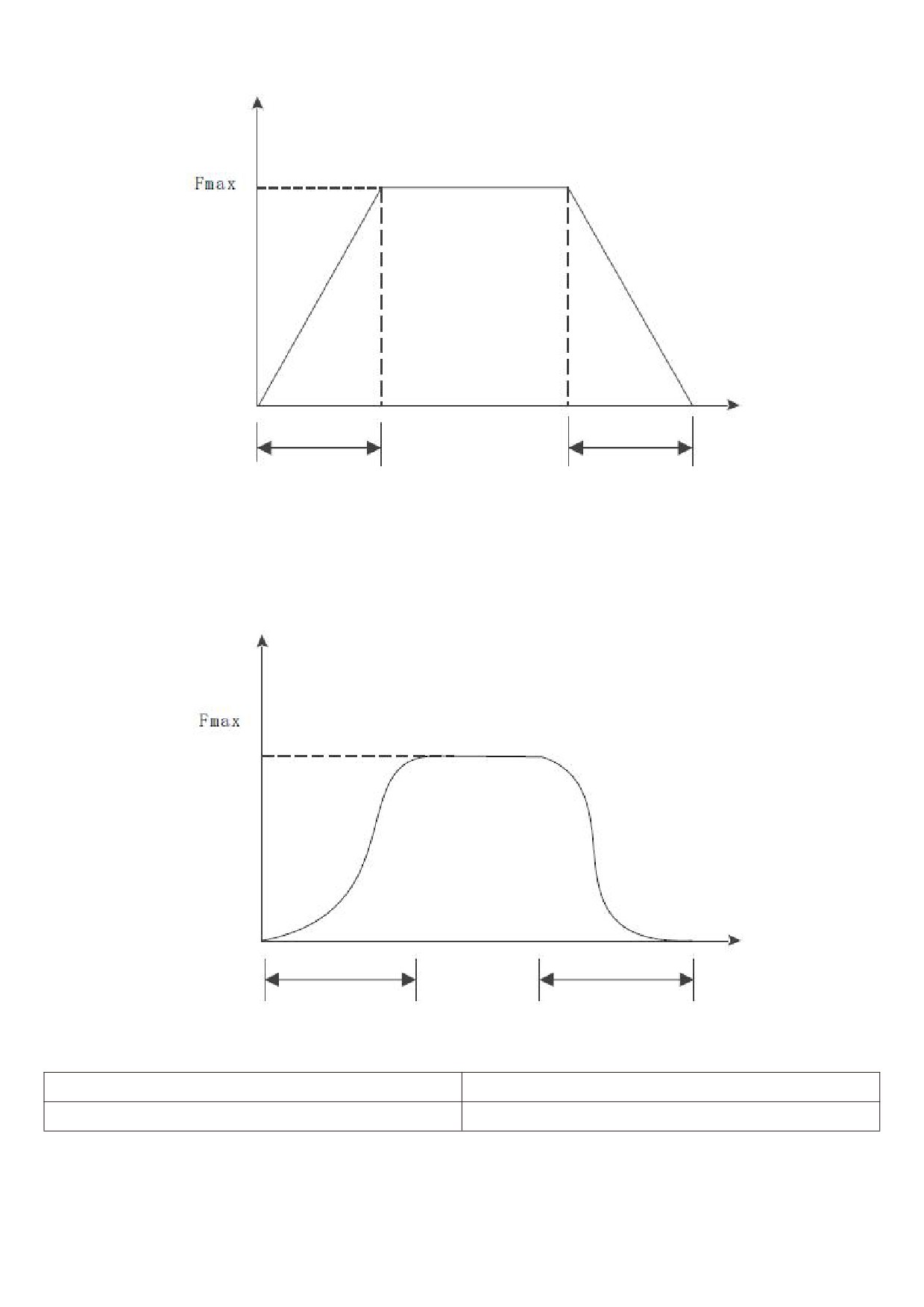
Frequency
Time
Acceleration time
Deceleration time
Figure 5 - 20 linear acceleration and deceleration
1: S curve acceleration and deceleration
The output frequency increases or decreases according to the S curve. The S curve is used in places that
require gentle start-up or shutdown, such as electric ladders and conveyor belts. The function codes F6 - 24 and F6 -
25 define the time ratios of the start and end segments of the S - curve acceleration and deceleration respectively.
Frequency
Time
Acceleration time
Deceleration time
Figure 5 - 21 S curve acceleration and deceleration
F6 - 24 S curve start period time proportion
0%~0.0%~(100.0%-F6-25) 【30%】
F6 - 25 S curve end period time proportion
0%~0.0%~(100.0%-F6-26) 【30%】
The function codes F6 - 24 and F6 - 25 respectively define the time ratio between the start and end periods of
the S curve acceleration and deceleration A and the two function codes shall meet the following requirements: F6-24
+ F6-25 ≤ 100.0%
96
F6-26 acceleration time 1 and acceleration time 2 switch
0.00Hz ~ maximum frequency 【0.00hz】
frequency points
F6-27 deceleration time 1 and deceleration time 2 switch
0.00Hz ~ maximum frequency 【0.00hz】
frequency points
During acceleration, if the operating frequency is less than F6 - 26, the acceleration time 2 is selected; if the
operating frequency is greater than F6 - 26, select acceleration time 1.
During deceleration, select deceleration time 1 if the operating frequency is greater than F6 - 27, and select
deceleration time 1 if the operating frequency is less than F6 -27 and the deceleration time 2 is selected.
F7 Group torque control
F7 - 00 speed / torque control mode
0~1 【0】
0: speed control mode.
1: torque control mode.
Notes:
The torque control mode is only valid in vector mode and VF control mode is invalid.
The X terminal has two functions related to torque control: torque control inhibits (function 29) and speed control
/ torque control switch (function 46). These two terminals should be used in conjunction with F7 - 00 to switch speed
and torque control.
F7 - 01 torque setting selection under torque control
0~7 【0】
mode
F7 - 01 is used to select the torque setting source. There are 8 torque setting methods.
Torque setting uses relative value, 100.0 % corresponding to the rated torque of the motor. Setting range -
200.0 % ~ 200.0 %, table the maximum torque of the Ming frequency inverter is twice the rated torque of the
frequency inverter.
When the torque is given to be positive, the frequency inverter is running in forward rotation
When the torque is given to be negative, the frequency inverter is running in reverse rotation
0: digital setting ( F7 - 03 )
Means that the target torque directly uses the F7 - 03 setting value.
1: AI1
2: AI2
3: AI3
Refers to the target torque is determined by the analog input terminal.
AI is given as torque, the voltage / current input corresponds to 100.0 % set, which refers to the percentage of
F7 - 03 set with respect to the torque number.
4. PULSE pulse (X5)
Target torque is given through terminal X5 high speed pulse.
Pulse given signal specification: voltage range 9V~30V, frequency range 0kHz~100kHz. Pulse given can only
be input from the multi-function input terminal X5.
The setting of 100.0 % corresponding to X5 terminal pulse input refers to the percentage of F7 - 03 set with
respect to the torque figure.
5. Communication given
Refers to the target torque is given by means of communication.
The host computer gives the data through the communication address 0x1000, and the data format is -
100.00 % - 100.00 %. 100.00 % refers to the percentage set by F7 - 03 with respect to the torque figure.
97
F7 - 02 small torque stop compensation
-50.0%~50.0% 【0.0%】
During torque control, the setting torque is too small to stop the traction load. At this time, F7 - 02 is added, and
the setting goes bigger, and the greater the torque during shutdown (note: not deceleration).
F7 - 04 torque control speed limit source
0~1【0】
0: set speed limit by F7 - 05 and F7 - 06.
When the torque setting is greater than 0, the upper frequency limit is given by F7 - 05; When the torque
setting is less than 0, the upper frequency limit is set by F7 - 06.
1: set by frequency source F0 - 03 frequency source.
When the torque is set to be 0, the upper frequency limit is determined by the frequency selected by F0 - 03.
When the torque is set to be 0, the upper frequency limit is F0 - 03 negative number of selected frequency.
F7-05Torque control forward maximum frequency
0.00Hz ~ maximum frequency 【50.00hz】
F7-06Torque control reverse maximum frequency
0.00Hz ~ maximum frequency 【50.00hz】
During torque control, the acceleration / deceleration time of the upper frequency limit is set at F7 - 09
(acceleration) / F7 - 10 (deceleration).
Used to set the maximum forward or reverse operating frequency of the frequency inverter in torque control
mode.
When the frequency inverter torque is controlled, if the load torque is less than the motor output torque, the
motor speed will continuously increase. In order to prevent accidents such as speeding in mechanical systems, it is
necessary to limit the maximum rotational speed of the motor during torque control.
If it is necessary to dynamically and continuously change the maximum frequency of torque control, the upper
limit frequency can be controlled.
F7-07 Torque given rise time
0.00s~650.00s 【0.00s】
F7-08 Given torque drop time
0.00s~650.00s 【0.00s】
Under the torque control mode, the difference between the motor output torque and the load torque determines
the speed change rate of the motor and the load. Therefore, the speed of the motor may change rapidly, which will
cause problems such as noise or excessive mechanical stress. By setting the torque control acceleration and
deceleration time, the rotation speed of the motor can be changed smoothly.
However, when torque is required to respond quickly, torque control acceleration and deceleration time should
be set to 0.00s.
F7-09 Torque control frequency rise time
0.00s~6500.00s 【20.00s】
F7-10 Torque control frequency drop time
0.00s~6500.00s 【20.00s】
F8 Group auxiliary function
F8 - 00 cumulative power-on arrival time setting
0h~65000h 【0h】
When the accumulated power-on time (U0 - 71) reaches the power-on time set by F8 - 00, the frequency inverter
multifunction (No. 24) digital DO outputs the on signal.
98
F8 - 01 cumulative run arrival time setting
0h~65000h 【0h】
When the accumulated operating time (U0 - 70) reaches this set operating time, the digital DO of the frequency
inverter multifunction (No. 12) outputs the on signal.
F8 - 02 Selection of G/P machine
1~2 【1】
1: G machine
2: P machine
Note: when modifying this function code, the motor group parameters will change accordingly.
F8 - 04 timing function selection
0~1 【0】
0: invalid
1: valid
F8 - 05 timing run time selection
0~3 【0】
0: set by F8 - 06
1: set by AI1 (100 % analog input range corresponds to F8 - 06)
2: AI2 setting (100 % analog input range corresponds to F8 - 06)
3: AI3 setting (100 % analog input range corresponds to F8 - 06)
F8 - 02 = 4, the frequency inverter starts timing when it starts. After reaching the set timing running time, the
frequency inverter stops automatically and the multi-function DO outputs an on signal at the same time.
Each time the frequency inverter starts, it starts counting from 0. The remaining running time of timing can be
checked through u0 - 20.
The timing run time is set by F8 - 05 / F8 - 06 and the time unit is min.
F8-06 timing run time
0.0Min~6500.0Min 【0.0Min】
F8-07 arrival time setting for this run
0.0Min~6500.0Min 【0.0Min】
When the running time of this startup reaches this time, the multi-function digital DO of the frequency inverter
outputs an on signal of “the running time reaches this time".
F8 - 08 skip frequency 1
0.00 Hz ~ maximum frequency [ 0.00Hz ]
F8 - 09 skip frequency 2
0.00 Hz ~ maximum frequency [ 0.00Hz ]
F8 - 10 skip frequency 3
0.00 Hz ~ maximum frequency [ 0.00Hz ]
F8 - 11 skip frequency 4
0.00 Hz ~ maximum frequency [ 0.00Hz ]
F8 - 12 jump frequency amplitude
0.00 Hz ~ maximum frequency [ 0.00Hz ]
99
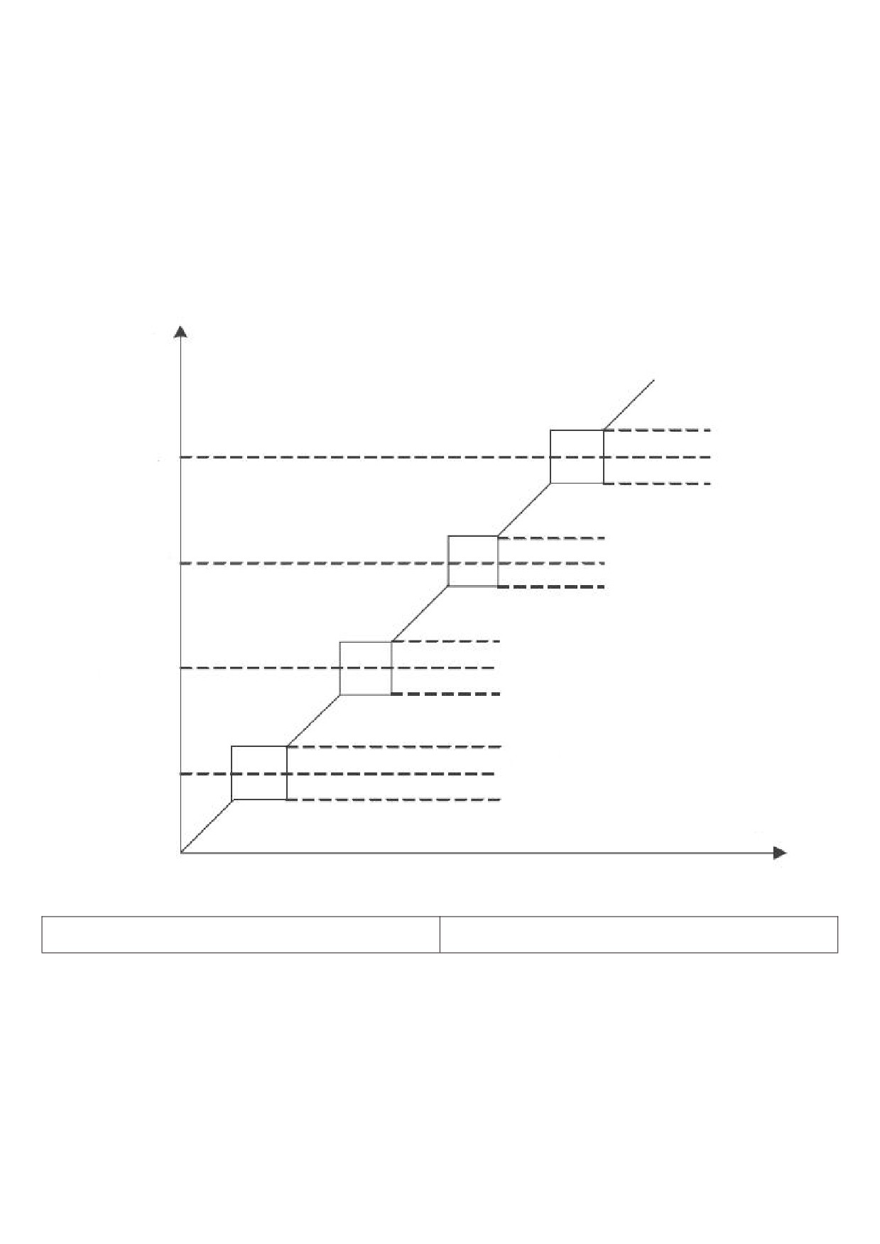
F8 - 08 ~ F8 - 12 are designed for the output frequency of the frequency inverter to avoid the resonance point of
the mechanical load.
When the set frequency is within the jump frequency range, the actual operating frequency will run in the jump
closer to the set frequency. By setting the jumping frequency, the frequency inverter can avoid the mechanical
resonance point of the load.
HV610 can set 4 hopping frequency points. If all 4 hopping frequencies are set to 0, the hopping frequency
function will be cancelled.
The conditions that must be met: The principle of hopping frequency 1 < = hopping frequency 2 < = hopping
frequency 3 < = hopping frequency 4
Hopping frequency and hopping frequency amplitude is illustrated herein with, please refer to figure 5 - 22.
Output frequency
/hz
Jumping amplitude
Hopping frequency 4
Jumping amplitude
Jumping amplitude
Hopping frequency 3
Jumping amplitude
Jumping amplitude
Hopping frequency 2
Jumping amplitude
Jumping amplitude
Hopping frequency 1
Jumping amplitude
Time /t
Figure 5 - 22 Hopping frequency diagram
F8 - 13 is the Hopping frequency valid during
0~1 【0】
acceleration and deceleration
This function code is used to set whether the skip frequency is valid during acceleration and deceleration.
F8 - 13 = 1, when the operating frequency is in the hopping frequency range, the actual operating frequency will
skip the set hopping frequency boundary. Figure 5 - 23 is a schematic diagram showing the valid jumping frequency
during acceleration and deceleration.
100
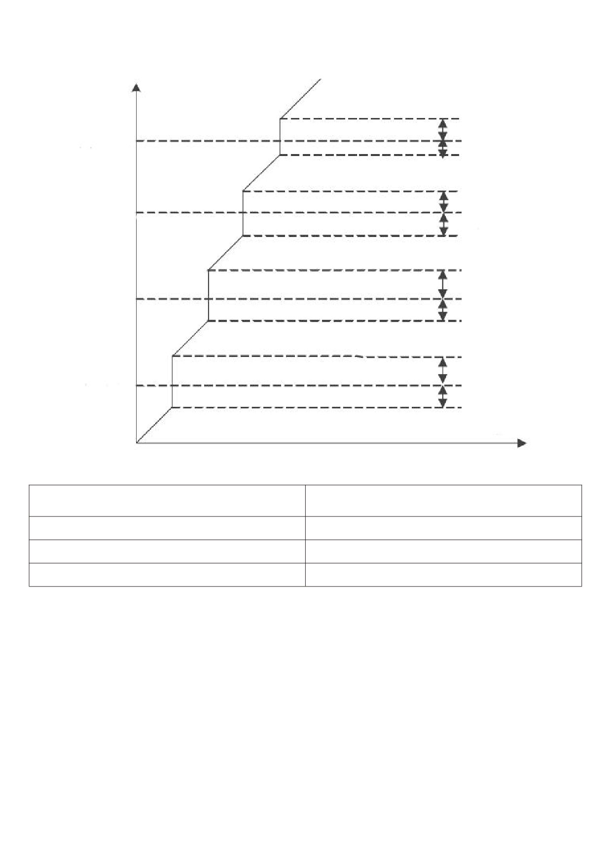
Output frequency
/hz
Jumping amplitude
Hopping frequency 4
Jumping amplitude
Jumping amplitude
Hopping frequency 3
Jumping amplitude
Jumping amplitude
Hopping frequency 2
Jumping amplitude
Jumping amplitude
Hopping frequency 1
Jumping amplitude
Time /t
Figure 5 - 23 valid diagram of jumping frequency during acceleration and deceleration
Sleep frequency ( F8 - 16 ) - maximum frequency ( F0 -
F8-14 wakeup frequency
10 ) 【0.00HZ】
F8-15 wake - up and delay time
0.0s~6500.0s 【0.0S】
F8-16 sleep frequency
0.00 Hz ~ wakeup frequency ( F8 - 14 ) [ 0.00 Hz ]
F8-17 sleep delay time
0.0s~6500.0s 【0.0S】
This set of parameters is used to realize sleep and wake-up functions in water supply applications.
During the operation of the frequency inverter, when the set frequency is less than or equal to the F8 - 16 sleep
frequency, the F8 - 17 delay time passes After that, the frequency inverter goes to sleep and stops automatically.
If the frequency inverter is in sleep state and the current operation command is valid, when the set frequency is
greater than or equal to F8 - 14 wake up Frequency, after a delay of time F8 - 15, the frequency inverter starts to
start.
In general, please set the wakeup frequency to be greater than or equal to the sleep frequency. Set the wake-up
frequency and sleep frequency to both 0.00 Hz, sleep and wake-up functions are invalid.
When the sleep function is enabled, if the frequency source uses PID, whether the sleep state PID is operated is
determined by the function code FA - 28, at this time must choose PID downtime calculation (FA - 28 = 1).
Note: during sleep, the running LED on the control panel blinks for 1s
101
F8 - 18 output power correction factor
0.0%~200.0%【100.0%】
When the output power (u0 - 05) does not correspond to the expected value, the output power can be linearly
corrected through this value.
F8 - 19 instantaneous power failure action selection
0~2 【0】
In the event of an instantaneous power failure or a sudden drop in voltage, the frequency inverter compensates
for the drop in DC bus voltage of the frequency inverter by reducing the output speed, so as to maintain the
frequency inverter's continuous operation.
0: this function is invalid.
1: slow down.
When the power is cut off or the voltage drops suddenly, the frequency inverter slows down. When the bus
voltage returns to normal, the frequency inverter is normal. Speed up recovery to set frequency operation. The basis
for judging the bus voltage to return to normal is that the bus voltage is normal and the duration exceeds the set time
of F8 - 21.
2: slow down and shut down.
In the event of an instantaneous power failure or a sudden drop in voltage, the frequency inverter slows down
until it stops.
F8-20 momentary stop action pauses judgment voltage
80.0%~100.0% 【90.0%】
F8-21 judging time of instantaneous power failure
0.00s~100.00s 【0.50s】
voltage rebound
F8-22 instantaneous power failure action judgment
60.0 % ~ 100.0 % ( standard bus voltage ) [ 80.0 % ]
voltage
F8 - 23 ~ F8 - 32 are specially designed for the textile industry. They are used in textile, chemical fiber and other
industries, as well as in occasions where horizontal movement and winding functions are required. They are simply
referred to as swing frequency functions.
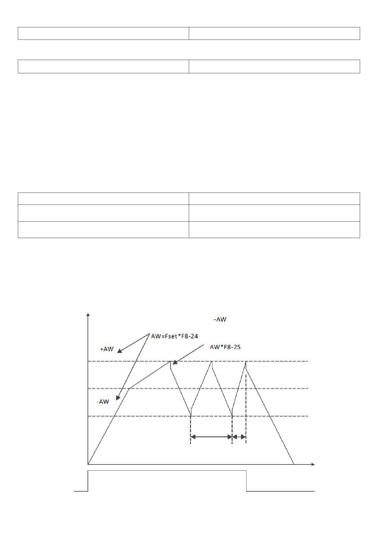
The pendulum frequency function is applicable to the pendulum frequency function. It refers to the frequency
output by the frequency inverter, which swings up and down around the set frequency. The track of the operating
frequency on the time axis is shown in figure 5 - 24. The swing amplitude is set by F8 - 23 and F8 - 24. When F8 - 24
is set to 0, the pendulum frequency will not work at this time.
Output frequency
Swing amplitude
Sudden jump frequency
Upper swing frequency
limit frequency
Pendulum frequency
center frequency
Pendulum frequency
lower limit frequency
Oscillating
Triangular
periodic
wave rise time
Time /t
Figure 5 - 24 schematic diagram of swing frequency operation
102
F8 - 23 swing setting method
0~1 [0]
This parameter is used to determine the reference amount of the swing.
0: relative center frequency (current frequency source), variable swing system. The swing amplitude changes
with the change of the center frequency (set frequency).
1: the relative maximum frequency (F0 - 16) is a fixed swing system, and the swing is fixed.
F8 - 24 swing amplitude
0.0%~100.0% [0.0%]
F8 - 25 sudden jump frequency amplitude
0.0%~50.0% [0.0%]
This parameter is used to determine the values of swing amplitude and sudden jump frequency.
When setting the swing relative to the center frequency (F8 - 23 = 0), swing aw = setting frequency X swing
amplitude F8 - 24.
When setting the swing relative to the maximum frequency (F8 - 23 = 1), the swing aw = maximum frequency F0
- 16 * swing amplitude F8-24.
The sudden jump frequency amplitude is the percentage of the sudden jump frequency relative to the swing
amplitude when the swing frequency is running, i.e. sudden adjustment frequency = swing amplitude aw * sudden
jump frequency amplitude F8 - 25.
If the swing amplitude is selected relative to the center frequency (F8 - 23 = 0), the sudden adjustment
frequency is a change value.
If the swing amplitude is selected relative to the maximum frequency (F8 - 23 = 1), the sudden adjustment
frequency is a fixed value.
The frequency of swing frequency operation is limited by the upper limit frequency and the lower limit frequency.
F8 - 26 frequency swing period
0.0s~3000.0s [10.0s]
F8 - 27 triangular wave rise time coefficient
0.0%~100.0% [50.0%]
Frequency swing period: the time value of a complete frequency swing period.
The triangular wave rise time coefficient F8 - 27 is the percentage of the triangular wave rise time relative to the
wobble period F8 - 26.
Triangular wave rise time = frequency swing period F8 - 26 × triangular wave rise time coefficient F8 - 27 in
seconds.
Triangle wave falling time = swing frequency period F8 - 26 × (1 - triangle wave rising time coefficient F8 - 27),
in seconds.
F8-28 set length
0m~65535m [1000m]
F8-29 actual length
0m~65535m [0m]
F8-30 number of pulses per meter
0.1~6553.5 [100.0]
The above function code is used for fixed length control.
Length information needs to be collected through a multifunctional digital input terminal, and the number of
pulses sampled by the terminal and the number of pulses per meter The actual length F8 - 29 can be calculated by
dividing F8 - 30.
During the fixed length control process, the length reset operation can be performed through the multi-function X
terminal (the X terminal function is selected as follows 28), please refer to F5 - 00 ~ F5 - 06 for details.
The corresponding input terminal function needs to be set to “length count input" (function 27) in the application.
In the pulse frequency X5 port must be used when it is high.
103
F8 - 31 set count value
1~65535 [1000]
F8 - 32 specifies the count value
1~65535 [1000]
The count value needs to be collected through the multifunctional digital input terminal. The corresponding input
terminal function needs to be set to “counter input" (function 25) in the application. When the pulse frequency is high,
X5 port must be used.
When the count value reaches the set count value F8 - 31, the multifunction digital DO outputs the “set count
value reaches" ON signal, and then the counter stops counting
When the count value reaches the specified count value F8 - 32, the multifunction digital DO outputs the
“specified count value reaches" ON signal. At this time, the counter continues counting until “set count value" when
the counter stops.
The specified count value F8 - 32 should not be greater than the set count value F8 - 31. The count value can be
viewed in u0 - 12.
F9 Group failure and protection
F9 - 00 motor overload protection selection
0~1 [1]
F9 - 01 motor overload protection gain
0.20~10.00 [1.00]
F9 - 00 = 0: motor overload protection is invalid.
F9 - 00 = 1: at this time, the frequency inverter judges whether the motor is overloaded according to the inverse
time limit curve of the motor overload protection.
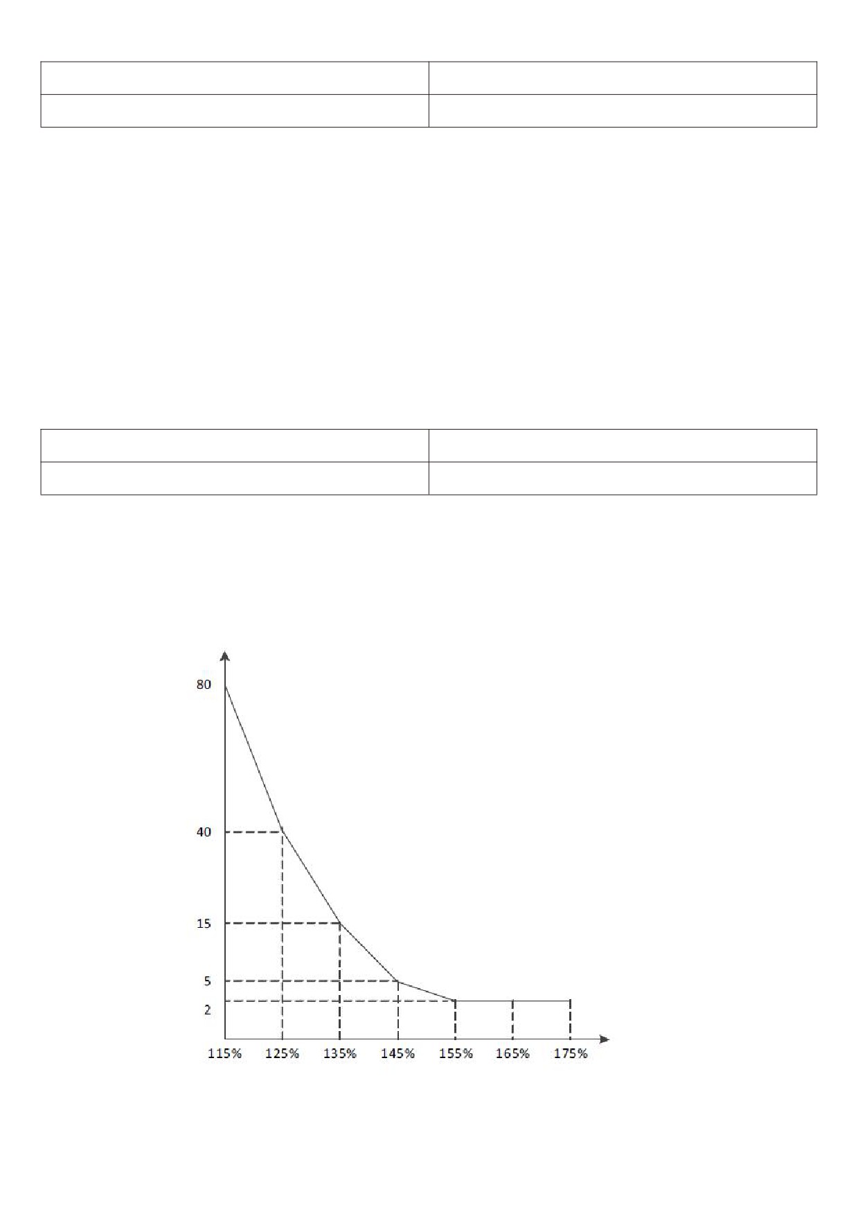
The shortest time to report motor overload is 2 minutes. If you need to adjust motor overload current and time,
please Set F9 - 01 (motor overload protection gain). The curve of motor overload current and overload time is shown
in the following figure:
Overload time
/min
Load /%
Figure 5 - 25 overload current vs. overload time curve
For example: if the motor is required to run at 120 % of the motor current for 30 minutes to report overload, the
default setting will be calculated first motor current IX overloaded for 30 minutes.
104