HV610 Series Frequency Inverter. User Manual (2021 V0.2 version) - page 5
According to the motor overload graph, if the 30 - minute overload is within the current range of 125 % and
135 %, then it can be concluded that the 30 - minute overload motor current IX under the default setting is as follows:
(40-30)÷ (125%-Ix) = (40-15) ÷ (125%-135%)
The result shows that the motor current IX = 129 %, so it can be concluded that the motor needs to overload for
30 minutes at 120 % of the motor current, and the motor overload protection gain:
F9-01=120%÷Ix=120%÷129%=0.93
Note: the user needs to set the value of F9 - 01 correctly according to the actual overload capacity of the
motor. If the parameter setting is too large, it is likely to cause overheating damage to the motor and the
frequency inverter does not give an alarm in time to protect it!
F9 - 02 motor overload warning coefficient
50%~100%[80%]
This function is used to give an early warning signal to the control system through do before motor overload fault
protection. This early warning coefficient is used to determine how much early warning is to be given before motor
overload protection. The higher the value, the smaller the advance warning amount
When the frequency inverter output current accumulation is greater than the product of the overload inverse time
limit curve and F9 - 02, the multi-function digital word DO of the frequency inverter outputs the “motor overload
pre-alarm" on signal
F9 - 03 over voltage stall gain
0~100 [30]
F9 - 04 stall over voltage point
200.0V~2000.0V [760.0%]
F9 - 03 = 0: over voltage stall protection function is invalid.
F9 - 03 non - 0: over voltage stall protection function is valid.
During the speed reduction of the frequency inverter, due to the influence of the load inertia, the actual decrease
of the motor speed may be lower than the decrease rate of the output frequency. At this time, the motor will feed back
electric energy to the frequency inverter, causing the voltage of the DC bus of the frequency inverter to rise. If no
measures are taken, an over voltage fault will occur.
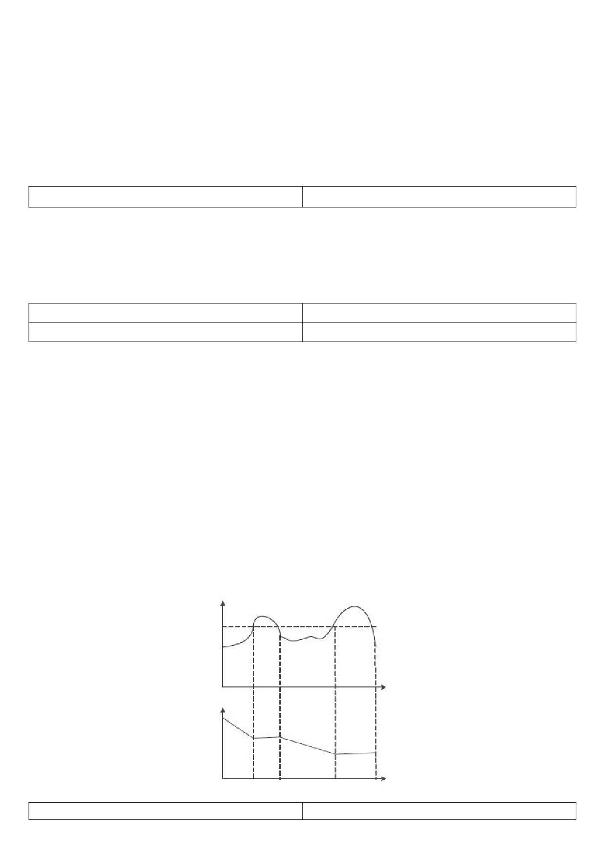
The over-voltage stall protection function detects the bus voltage during the deceleration operation of the
inverter, and compares with the stall over-voltage point F9 - 04. If the stall voltage is exceeded, the output frequency
of the inverter stops falling. When the bus voltage is lower than the stall over-voltage point, the deceleration
operation is implemented again.
F9 - 03 the greater the over voltage stall gain setting, the stronger the ability to suppress over voltage. However,
on the premise that no over voltage occurs, the smaller the benefit increase setting is, the better.
For loads with small inertia, the over-pressure stall gain should be small; otherwise the system's dynamic
response will slow down.
For large inertia loads, this value should be large; otherwise, the suppression effect is not good and over voltage
faults may occur.
Stall over voltage point
Time
Output frequency
Time
Figure 5 - 26 over voltage stall function
F9 - 05 over loss rate gain
0~100 [20]
105
F9 - 06 stall flow point
100%~200% [150%]
Over current speed: when the frequency inverter output current reaches the set over current stall protection
current (F9 - 06), the frequency inverter will reduce the output frequency when accelerating operation; Reduce the
output frequency during constant speed operation; During deceleration operation, the speed of descent is slowed
down until the current is less than the over current stall protection current (F9 - 06) before the operating frequency
returns to normal.
Over current stall protection current: select the current protection point with over current speed function. The
frequency inverter starts to perform over-current stall protection function beyond this parameter value. This value is
the percentage of the rated current of the motor.
Over - loss speed gain: used to adjust the frequency inverter's ability to suppress over-current during
acceleration and deceleration. The greater the value, the stronger the ability to suppress over current on the premise
of no over current, and the smaller the gain setting, the better.
For loads with small inertia, the over-loss rate gain should be small; otherwise the system's dynamic response
will slow down.
For loads with large inertia, this value should be large; otherwise, the suppression effect is not good and over
current faults may occur.
When the inertia is very small, it is recommended to set the over current suppression gain to less than 20. The
over-run speed gain is set to 0, the over-run speed function will be cancelled.
F9 - 07 selection of short circuit protection from power
0~1 [1]
on to ground
0: power-on short circuit test to ground is invalid.
1: power-on short circuit detection to ground is valid.
This function is valid, and then the uvw end of the frequency inverter will have a voltage output for a period of
time after power - up, which will last for 500 Ms.
F9 - 09 number of automatic resets for faults
0~20 [0]
The automatic fault reset function can automatically reset faults in operation according to the set number of
times and interval F9 - 11. When the number of automatic resets is set to 0, automatic resets are prohibited and fault
protection is performed immediately.
F9 - 10 fault DO action selection during automatic fault
0~1 [0]
reset
0: during the fault, the fault DO does not output.
1: fault DO output during fault.
F9 - 11 fault DO action selection during automatic fault
0.1s~100.0s[1.0s]
reset
F9 - 12 input phase missing \ contactor suction
00~11[11]
protection selection
Bit: input phase missing protection
0: input phase missing does not fail.
1: the panel displays IPL if the input is out of phase.
10 bits: contactor suction protection
0: contactor failure when not suction.
1: failure when contactor does not suck, panel shows ref
F9 - 13 selection of out-of-phase protection for output
0~1 [1]
0: no fault protection when the output is out of phase.
1: when the output is out of phase, fault protection and OPL are displayed on the panel.
F9 - 14 fault protection action selection 1
00000~22222 [00000]
Bits: motor overload fault OL2
106
10 bits: input phase failure IPL.
100 bits: output phase-missing fault OPL.
1000 bits: external failure ETF.
10,000 bits: communication failure COF.
0: free parking. Once OL2 fails, stop the parking freely.
1: stop the machine according to the set stop method.
2: continue running.
F9 - 15 fault protection action selection 2
00000~22222
[00000]
Bit:
10 bits: EEPROM fault EPF.
100 bits: reserved.
1000 bits: reserved.
10,000 bits: accumulated time reaches RTAF.
0: free parking.
1: stop the machine according to the set stop method.
2: continue running.
F9 - 16 fault protection action selection 3
00000~22222
[00000]
Bit: custom fault uEF1.
10 bits: user-defined fault uEF2.
100 bits: power-on time reaches faulty utF.
1000 bits: load shedding fault LLf.
10,000 bits: PID feedback lost fault PIDF.
0: free parking.
1: stop the machine according to the set stop method.
2: continue running.
F9 - 17 fault protection action selection 4
00000~22222
[00000]
Bit: failure DEU due to excessive speed deviation.
10 digits: motor over speed OSF.
100 bits: initial position error POF.
1000 bits: load shedding fault LLF.
10,000 bits: reserved.
0: free parking.
1: stop the machine according to the set stop method.
2: continue running.
F9 - 21 continue operating frequency selection in case
0~4 [0]
of failure
0: run at current operating frequency
1: run at the set frequency
2: run at the upper limit frequency
3: the following limited frequency operation
4: run at abnormal standby frequency.
If a fault occurs during the operation of the frequency inverter, and the processing method of the fault is set to
continue running, F9 - 21 will be used for confirmation run at a fixed frequency.
When selecting an abnormal standby frequency to run, the value set by F9 - 22 is a percentage of the maximum
frequency.
107
F9 - 22 abnormal standby frequency
0.0 % - 100.0 % ( maximum frequency ) [ 100.0 % ]
F9 - 23 motor sensor type
0~2【0】
0: no temperature sensor.
1:PT100.
2:PT1000.
F9 - 24 motor overheating threshold
0℃~200℃【110】
F9 - 25 motor overheating warning threshold
0℃~200℃【90】
The sensor type must be set correctly for using, and the motor temperature value is displayed in U0 - 34.
When the motor temperature (U0 - 34) exceeds the motor overheat protection threshold F9 - 24, the frequency
inverter fails to give an alarm.
When the motor temperature (u0 - 34) exceeds the motor overheat warning threshold, the multi-function digital
output “motor overheat warning" of the frequency inverter will output a signal.
F9 - 26 off-load protection options
0~1【0】
0: invalid.
1: valid.
0.0 % ~ 100.0 % ( rated current of motor )
F9 - 27 load shedding test level
【10.0%】
F9 - 28 off-load test time
0.0s~60.0s【1.0s】
F9 - 26 off-load protection function is valid, when the frequency inverter output current is less than the off-load
detection level F9 - 27 and the duration is greater than the off-load detection time F9 - 28, and the frequency inverter
output frequency is automatically reduced to 7 % of the rated frequency. During the period of off-load protection, if
the load recovers, the frequency inverter will automatically resume operating at the set frequency.
F9 - 30 over-speed detection value
0.0 % - 50.0 % ( maximum frequency )【20.0 %】
F9 - 31 over-speed detection time
0.0s~60.0s【1.0s】
When the frequency inverter detects that the actual rotational speed of the motor exceeds the maximum
frequency, the exceeding value is greater than the over-speed detection value F9 - 30, and the duration is greater
than the over-speed detection time F9 - 31, the frequency inverter fails to alarm OSF, and processes it according to
the failure protection operation mode.
If the over-speed detection time F9 - 31 is 0.0s, the over-speed fault detection will be cancelled.
F9 - 32 speed deviation too large detection value
0.0 % - 50.0 % ( maximum frequency ) [ 20.0 % ]
F9 - 33 excessive speed deviation detection time
0.0s~60.0s【5.0s】
When the frequency inverter detects that the actual rotation speed of the motor deviates from the set frequency,
the deviation is greater than the measured value F9 - 32 of excessive speed deviation, and the duration is greater
than the detected time F9 - 33 of excessive speed deviation, the frequency inverter fails to give an alarm DEU and
processes it according to the failure protection action mode.
When the detection time for excessive speed deviation is 0.0s, the fault detection for excessive speed deviation
will be cancelled.
108
FA Group process control PID function
PID control is a common method of process control. By performing proportional, integral and differential
operations on the difference between the feedback signal of the controlled quantity and the target signal, and
adjusting the output frequency of the frequency inverter, a closed loop system is formed to stabilize the controlled
quantity at the target value.
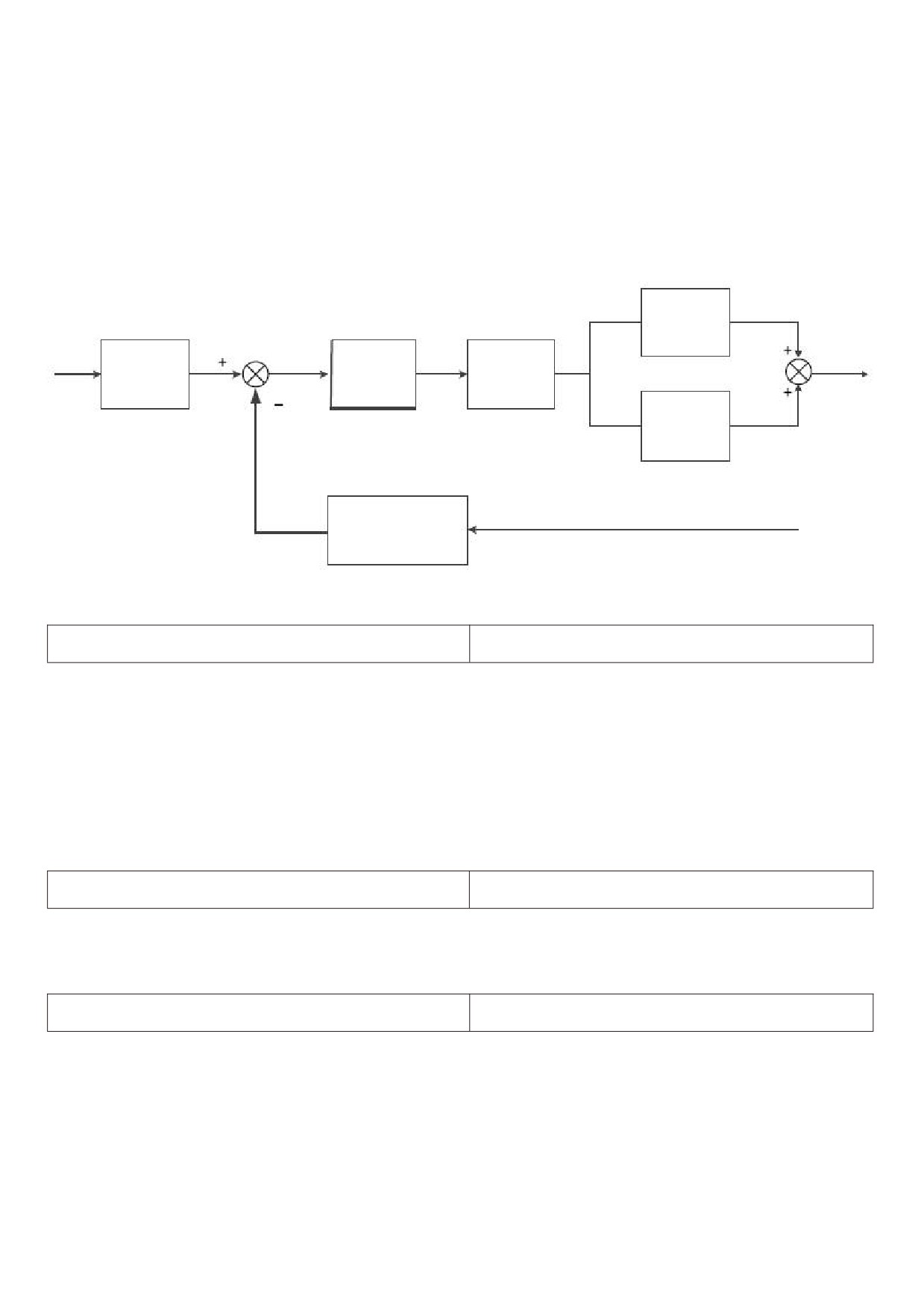
Suitable for flow control, pressure control, temperature control and other process control occasions. Figure 5 -
27 is the control principle block diagram of process PID.
Kp effect
FA - 05
PIDpositive
Given quantity
Deviation limit
and negative
FA-00/FA-01
FA-09
FA - 03
Integral and
Closed loop
differential
output
action
FA-06/FA-07
Closed loop feedback quantity
Feedback quantity
FA-02
Figure 5 - 27 process PID principle block diagram
FA - 00 PID given channel selection
0~6【0】
0: FA - 01 setting.
1:AI1.
2:AI2
3:AI3
4: X5 pulse setting
5: communication settings.
6: multi-speed setting.
7: FA-01 setting (up/down can be changed)
FA - 01 PID digital setting
0.0%~100.0%【50.0%】
The setting target amount of the process PID is a relative value, and the setting range is 0.0 % - 100.0 %.
Similarly, the feedback quantity of PID is also a relative quantity, and the function of PID is to make these two relative
quantities the same.
FA - 02 PID feedback channel selection
0~8【0】
0:AI1。
1:AI2
2:AI3
3:AI1-AI2
4: X5 pulse quantity
5: communication.
6:AI1+AI2
7:MAX (|AI1|, |AI2|)
109
8: MIN (|AI1|, |AI2|)
The feedback amount of the process PID is also a relative value, and the setting range is 0.0 % - 100.0 %.
FA - 03 PID direction of action
0~1 [0]
0: positive effect
When the feedback signal of PID is less than a given amount, the output frequency of the frequency inverter
increases. Such as tension control occasions for winding.
1: reaction.
When the feedback signal of PID is less than a given amount, the output frequency of the frequency inverter will
be decreased Such as tension control occasions for unwinding.
This function is affected by the reversal of the direction of action of the multi-function terminal PID (function 35),
which requires attention in use.
FA - 04 PID gives feedback range
10~65535 【1000】
PID given feedback range is dimensionless unit, used for PID given display U0 - 15 and PID feedback display u0
- 16.
The relative value of the given feedback of PID is 100.0 %, corresponding to the given feedback range FA - 04.
For example, if FA - 04 is set to 2000, when the PID is given 100.0 %, the PID given display u0 - 15 is 2000.
FA-05 proportional gain Kp1
0.0~100.0 [20.0]
FA-06 integration time Ti1
0.01s~10.00s [2.00S]
FA-07 differential time Td1
0.00~10.000 [0.000s]
Proportional gain Kp1:
Determining the adjusting intensity of the whole PID regulator, the greater kp1, the greater the adjusting intensity.
The parameter is 100. 0 indicates when PID is inverted when the deviation between the feed quantity and the given
quantity is 100.0 %, the regulating amplitude of the PID regulator to the output frequency command is the maximum
frequency.
Integration time Ti1:
Determines the strength of integral adjustment of PID regulator. The shorter the integration time, the greater the
adjustment intensity the integration time refers to when the deviation between the PID feedback quantity and the
given quantity is 100.0 %, the integral regulator continuously adjusts after this time, and the adjustment quantity
reaches the maximum frequency.
Differential time Td1:
Determines the strength of the PID regulator to adjust the deviation rate of change. The longer the differentiation
time, the greater the adjustment intensity Differential time it means that when the feedback amount changes by
100.0 % within this time, the adjustment amount of the differential regulator is the maximum frequency.
FA - 08 PID inversion cutoff frequency limit
0.00 ~ maximum frequency [0.00 Hz]
In some cases, only when the output frequency of the PID is negative ( i.e. the frequency inverter inverts ), can
the PID control the given amount and the feedback amount to the same state, but too high an inversion frequency is
not allowed in some cases, and FA - 08 is used to determine the upper limit of the inversion frequency.
FA - 09 PID deviation limit
0. 0%~100.0% [0.0%]
When the deviation between the given PID quantity and the feedback quantity is less than FA - 09, the PID stops
the adjusting action, and the output frequency is stable when the deviation between the given quantity and the
feedback is small.
110
FA - 10 PID differential clipping
0.00%~100.00%【0.10%】
In PID regulator, the function of differentiation is relatively sensitive, which easily causes system oscillation.
The function of PID differentiation is limited to a small range.
FA - 11 PID given change time
0.00s~650.00s【0.00s】
The given change time of PID refers to the time required for the given value of PID to change from 0.0 % to
100.0 %.
When the PID given value changes, the PID given value changes linearly according to the given change time,
thus reducing the occurrence of mutation in the given value adverse impact on the system
FA- 12 PID feedback filtering time
0.00s~60.00s【0.00s】
FA - 13 PID output filtering time
0.00s~60.00s【0.00s】
FA- 12 is used to filter the PID feedback quantity. The filter is helpful to reduce the influence of the feedback
quantity being interfered, but it will bring about a decrease in the response performance of the process closed loop
system.
FA- 13 is used to filter the PID output frequency. This filter will weaken the abrupt change of the frequency
inverter output frequency, but it will also bring about a decrease in the response performance of the process closed
loop system.
FA-15
Proportional gain kp2
0.0~100.0【20.0】
FA-16
Integration time Ti2
0.01s~10.00s【2.00S】
FA-17
Differential time Td2
0.00~10.000【0.000s】
In some applications, a group of PID parameters cannot meet the requirements of the whole operation process,
and different PID parameters need to be adopted in different situations.
The above function code is used for switching the two groups of PID parameters. The setting mode of regulator
parameters FA - 15 ~ FA - 17 is similar to parameters FA - 05 ~ FA - 07.
FA - 18 PID parameter switching conditions
0~3【0】
0: do not switch, only use the first group of PID (FA - 05 ~ FA - 07) parameters.
1: switch through X terminal. Multi-function X terminal function selection to be set to 43 (PID parameter switching
terminal), when the terminal is invalid, select the parameter
Group 1 (FA - 05 ~ FA - 07), select parameter group 2 (FA - 15 ~ FA - 17) when the terminal is active
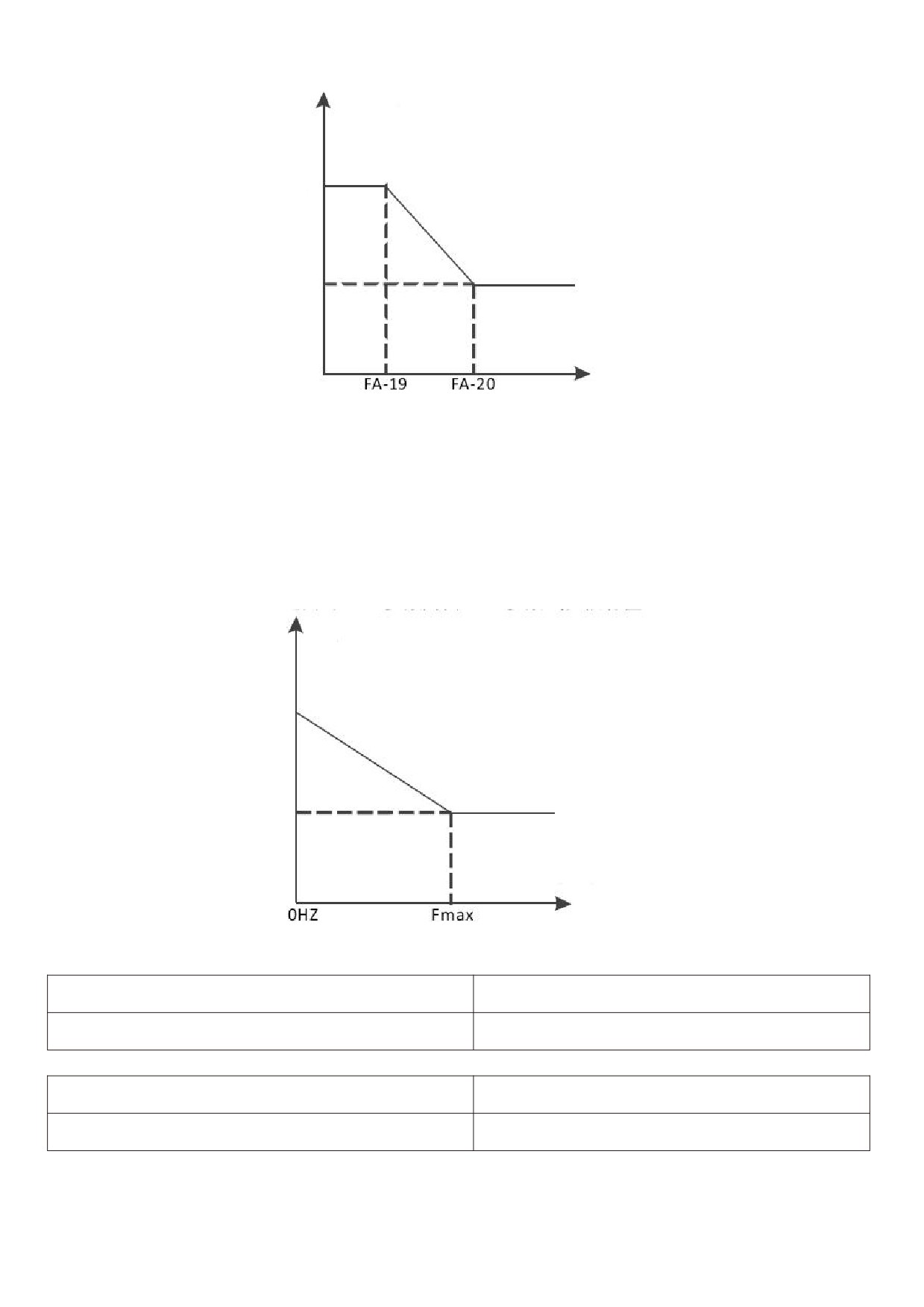
2: switch automatically according to deviation.
Given the absolute value of deviation from feedback is less than PID parameter switching deviation 1 (FA - 19),
PID parameter selection parameter group 1.
Given that the absolute value of the deviation from the feedback is greater than PID switching deviation 2 (FA -
20), PID parameter selection selects parameter group 2.
Given that the deviation from feedback is between switching deviation 1 and switching deviation 2, the PID
parameters are linear interpolation values of two sets of PID parameters, as shown in figure 5 - 28.
111
PID parameter
PID parameter 1
FA - 05 / 06 / 07
PID parameter 2
FA - 15 / 16 / 17
PID deviation
Figure 5 - 28 schematic diagram of PID switching based on deviation
3: automatically switch according to operating frequency.
When the absolute value of the output frequency is equal to 0, the PID parameter selects parameter group 1.
When the absolute value of the output frequency is equal to the maximum frequency (F0 - 16), PID parameter
selection selects parameter group 2.
When the output frequency is between 0 Hz and the maximum frequency, the PID parameters are linear
interpolation values of two groups of PID parameters, as shown in figure 5 - 29.
PID deviation
PID parameter 1
FA - 05 / 06 / 07
PID parameter 2
FA - 15 / 16 / 17
Output frequency / Hz
Figure 5 - 29 schematic diagram of PID switching according to operating frequency
FA - 19 PID parameter switching deviation 1
0.0%~FA-20【20.0%】
FA - 20 PID parameter switching deviation 2
FA-19~100.0%【80.0%】
FA - 21 PID initial value
0.0%~100.0%【0.0%】
FA - 22 PID initial value holding time
0.00s~650.00s【0.00s】
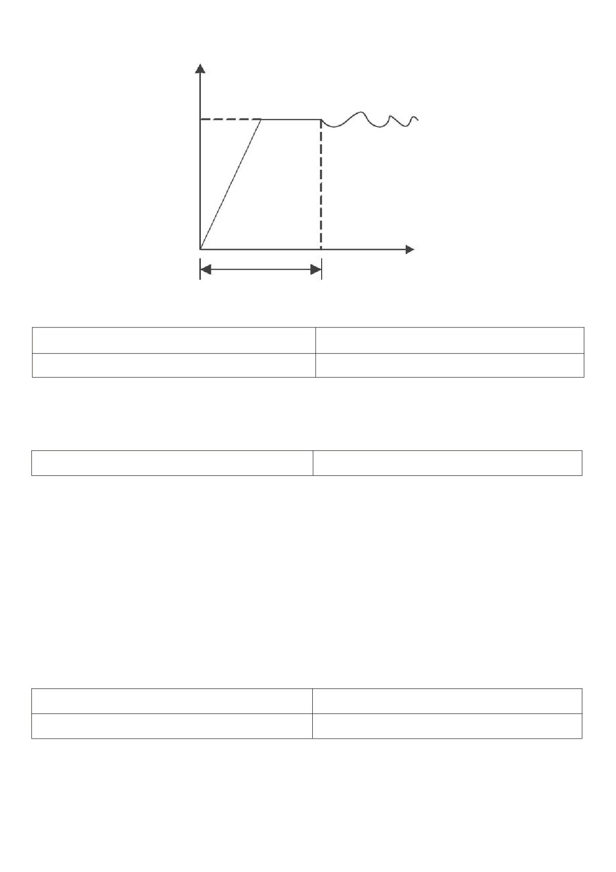
When the frequency inverter is started, the PID output is fixed to the PID initial value FA - 21, and after the PID
initial value keeping time FA - 22 is continued, PID began the closed loop adjustment operation. Figure 5 - 30 is a
functional diagram of the initial PID value.
112
PID output
Initial value
FA-21
Time
FA- 22 initial value
maintenance time
Figure 5 - 30 functional diagram of PID initial value
FA - 23 twice output deviation positive maximum
0.00%~100.00%【1.00%】
FA - 24 twice output deviation reverse maximum
0.00%~100.00%【1.00%】
This function is used to limit the difference between the two beats (2 ms / beat) of the PID output so as to
prevent the PID output from changing too fast and stabilize the operation of the frequency inverter.
FA - 23 and FA - 24 respectively correspond to the maximum absolute value of the output deviation in forward
and reverse directions.
FA - 25 PID integral attribute
00~11【00】
Bit: PID integral separation
0: invalid.
No matter what kind of state, Ti integral of PID plays a role.
1: valid.
When the multifunctional digital X - terminal integral pause (function 22) is valid, the integral PID integral of the
PID stops the operation, and at this time the PID only has proportional and differential effects.
Ten digits: whether to stop integrating after outputting to the limit value.
0: continue to score.
When the PID outputs to the upper limit frequency or the lower limit frequency, the integral calculation will
continue.
1: stop points.
When the PID is output to the upper limit frequency or the lower limit frequency, the calculation of the PID
integral will stop at this time, which may help to reduce the overshoot of the PID.
FA- 26 PID feedback loss detection value
0.1%~100.0%【0.0%】
FA - 27 PID feedback loss detection time
0.0s~20.0s【0.0s】
When FA - 26 = 0.0, PID does not judge that feedback is lost;
When FA - 26 is not 0, when the PID feedback amount is less than the feedback loss detection value FA - 26 and
the duration exceeds the PID feedback loss detection time FA - 27, the frequency inverter alarms the fault pidf and
processes it according to the selected fault processing method.
113
FA - 28 PID shutdown operation
0~1【0】
0: stop without calculation.
1: stop operation.
Use to select whether the PID will continue to operate under the shutdown state of the PID. In general
applications, PID should the operation should be stopped.
FA - 29 pressure sleep option
0~1【0】
0: the frequency inverter sleeps and wakes up according to the frequency node according to the functions of F8 -
14 ~ F8 - 17.
1: the frequency inverter sleeps and wakes up according to the pressure node according to the functions of FA -
30 ~ FA - 33.
FA - 30 wake-up pressure percentage
0.0~100.0%【80.0%】
FA - 31 wake-up pressure delay time
0~6000.0【1.0】
Wake up pressure percent = (wake up pressure / target pressure) X 100 %.
When the feedback pressure is less than the wake-up pressure, it will enter the wake-up state after FA - 31
times.
FA - 32 sleep pressure percentage
50.0~1000.0%【80.0%】
FA - 33 sleep pressure delay time
0~6000.0【60.0】
Sleep pressure percentage = (sleep pressure / target pressure) X 100 %.
When the feedback pressure is greater than the sleep pressure, it will enter the sleep state.
Note: during sleep, the operation indicator on the control panel flashes for 1s cycle.
FB Group 2 motor parameters
HV610 can switch operation between two motors. The two motors can respectively set motor nameplate
parameters and can respectively enter Line motor parameter tuning, VF control or vector control can be selected
separately, encoder related parameters can be set separately, and parameters related to VF control or vector control
performance can be set separately.
The Fb group function code corresponds to all parameters of the motor 2 and FB group. Its content definition
and usage method are consistent with those of the first motor. This will not be repeated here. The user can refer to
the description of the relevant parameters of the first motor. The specific FB - 00 ~ FB - 37 refers to f1 - 00 ~ f1 - 37
group parameters, and FB - 38 ~ FB - 55 refers to F2 - 00 ~ F2 - 17 parameters.
FB - 61 2nd motor control mode
0~2【0】
When the motor is selected as the second motor, the control mode takes effect, and the definitions of 0 ~ 2 are
the same as F0 - 01.
0: no PG open loop vector control
1: PG closed loop vector control
2:V/F
FB - 62 second motor acceleration and deceleration time
0~4【0】
selection
0: the acceleration and deceleration time is the same as that of the first motor.
1: the first group of acceleration and deceleration time
114
2: acceleration and deceleration time of the second group
3: acceleration and deceleration time of the third group
4: the fourth group of acceleration and deceleration time
FB - 63 2nd motor torque boost
0.0 % ~ 30.0 % [model determination]
Same as F3 - 01 torque boost function of the first motor.
FB - 64 second motor oscillation suppression gain
0 ~ 100 [model determination]
Same as F3 - 11 oscillation suppression function of the first motor.
FC Group multi-segment instruction and simple PLC function
HV610 multi-segment instruction has more abundant functions than usual multi-segment speed. Besides
realizing multi-segment speed function, it can also be used as a voltage source for VF separation and a given source
for process PID. For this reason, the dimension of the multi-segment instruction is a relative value.
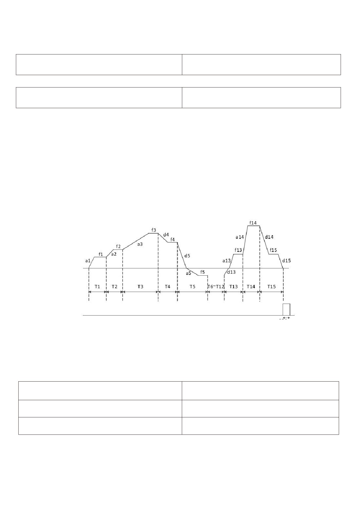
The simple PLC function is a multi-section speed generator. The frequency inverter automatically numbers the
running frequency and direction according to the running time to meet the technological requirements. The function
was previously completed by the PLC (programmable controller) and now depends on the frequency inverter.As
shown in figure 5 - 31.
Plc operation
D0 or relay
Plc cycle completion instruction
250ms
Figure 5 - 31 simple PLC operation diagram
In fig. 5 - 31, a1 ~ a15 / D1 ~ d15 are the acceleration and deceleration times of the stage where they are
located, while f1 ~ f15 and t1 ~ t15 are the set frequencies and stage operation times of the stage where they are
located.
FC-00
Multi - segment instruction 0
-100.0%~100.0%【0.0%】
FC-01
Multi - segment instruction 1
-100.0%~100.0%【0.0%】
FC-02
Multi - segment instruction 2
-100.0%~100.0%【0.0%】
115
FC - 03 multi-segment instruction 3
-100.0%~100.0%【0.0%】
FC - 04 multi-segment instruction 4
-100.0%~100.0%【0.0%】
FC - 05 multi-segment instruction 5
-100.0%~100.0%【0.0%】
FC - 06 multi-segment instruction 6
-100.0%~100.0%【0.0%】
FC - 07 multi-segment instruction 7
-100.0%~100.0%【0.0%】
FC - 08 multi-segment instruction 8
-100.0%~100.0%【0.0%】
FC - 09 multi-segment instruction 9
-100.0%~100.0%【0.0%】
FC - 10 multi-segment instruction 10
-100.0%~100.0%【0.0%】
FC - 11 multi-segment instruction 11
-100.0%~100.0%【0.0%】
FC - 12 multi-segment instruction 12
-100.0%~100.0%【0.0%】
FC - 13 multi-segment instruction 13
-100.0%~100.0%【0.0%】
FC - 14 multi-segment instruction 14
-100.0%~100.0%【0.0%】
FC - 15 multi-segment instruction 15
-100.0%~100.0%【0.0%】
Multi-segment instruction can be used in three situations: multi-segment speed as frequency source, simple
PLC, voltage source as VF separation, and setting source of process PID.
In the three applications, the dimension of the multi-segment instruction is the relative value, ranging from -
100.0 % to 100.0 %.
Which is the percentage of the relative maximum frequency when used as the frequency source.
When VF is used as a separate voltage source, it is a percentage of the rated voltage of the motor.
Given the relative value of PID, multi-segment instructions as the PID setting source do not require dimensional
conversion.
The multi-segment instructions need to be switched and selected according to different States of the
multi-function digital X terminal,please refer to F5 group for details relevant instructions.
FC - 16 simple PLC operation mode
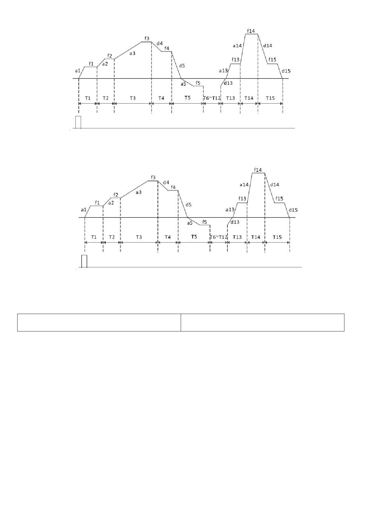
1~2【0】
0: stop after single operation. As shown in figure 5 - 32, the frequency inverter stops automatically after
completing one cycle, and it needs to be transported again to run.
116
Plc operation
Run command
Figure 5 - 32 shutdown modes after single cycle
1: Maintain the final value at the end of a single run. As shown in figure 5 - 33, the frequency inverter
automatically maintains the operating frequency of the last section after completing one cycle.
Plc operation
Run command
Figure 5 - 33 PLC maintains final value after single cycle
2: Keep running in a cycle.
After the frequency inverter completes one cycle, it will automatically start the next cycle until there is a stop
command.
FC - 17 Simple PLC memory selection
00~11【00】
Bit: power failure memory option.
0: no memory when power fails.
When power is lost, the PLC operation state will not be memorized. When power is turned on, the PLC will start
to run again from the first stage.
1: power failure memory.
When power is lost, the PLC operation status, including operation phase and frequency, and the time that has
already been run, will be memorized. Continue to run from the memory stage after power - up.
Ten digits: stop memory option.
0: stop the machine and do not remember.
Each start-up starts from the first stage.
1: stop memory.
PLC shutdown memory is to record the previous PLC operation phase and frequency during shutdown, and
continue to operate from the memory stage during the next operation.
117
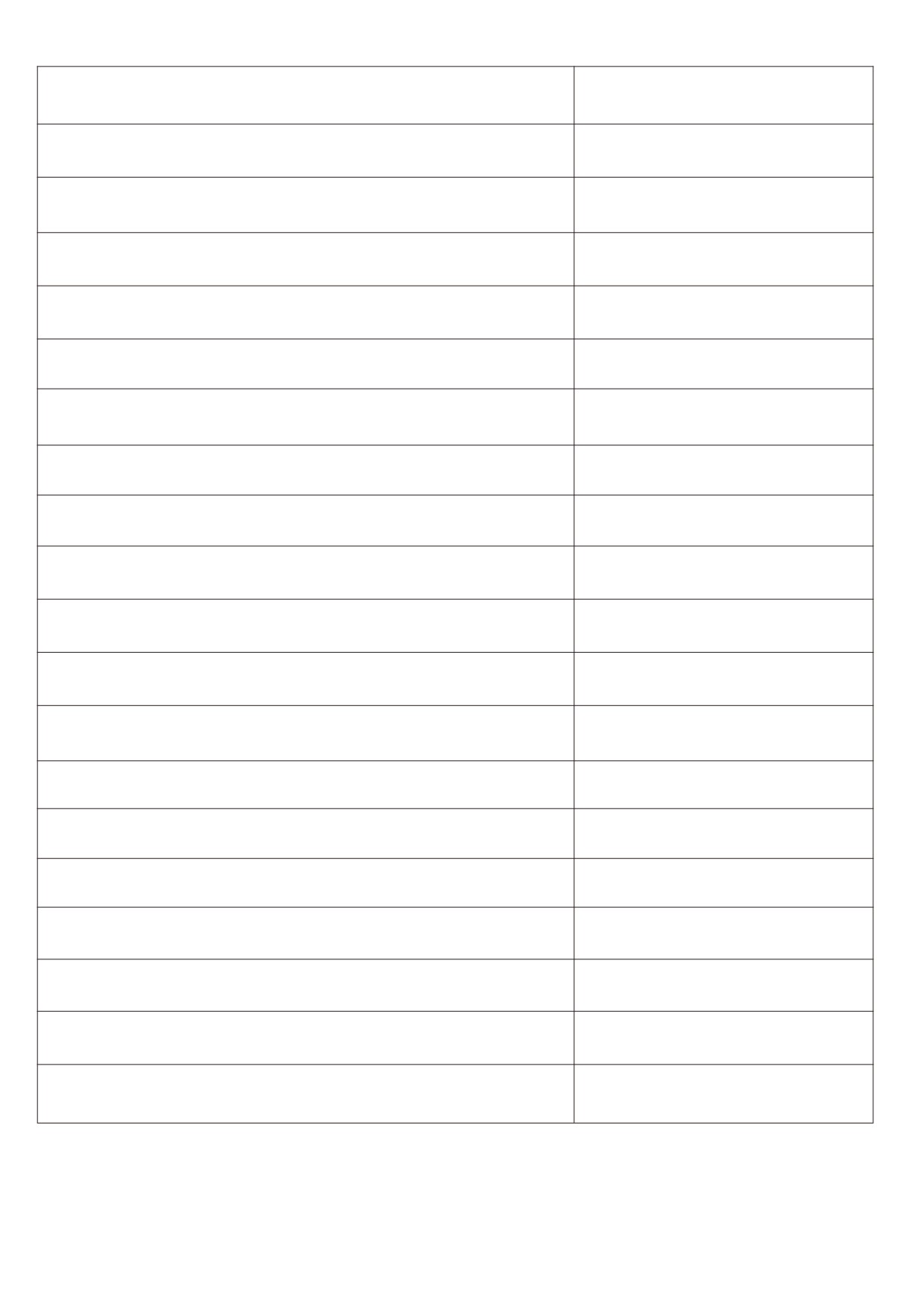
FC -
18
Simple PLC section 0 operation time
0.0s(h)~6500.0s(h)【0.0s(h)】
FC -
19
Simple PLC section 0 acceleration and deceleration time
0~3【0】
FC -
20
Simple PLC first run time
0.0s(h)~6500.0s(h)【0.0s(h)】
FC -
21
Simple PLC first acceleration and deceleration time
0~3【0】
FC -
22
Simple PLC section 2 operation time
0.0s(h)~6500.0s(h)【0.0s(h)】
FC -
23
Simple PLC second acceleration and deceleration time
0~3【0】
FC -
24
Simple PLC section 3 operation time
0.0s(h)~6500.0s(h)【0.0s(h)】
FC -
25
Simple PLC section 3 acceleration and deceleration time
0~3【0】
FC -
26
Simple PLC section 4 operation time
0.0s(h)~6500.0s(h)【0.0s(h)】
FC -
27
Simple PLC section 4 acceleration and deceleration time
0~3【0】
FC -
28
Simple PLC section 5 operation time
0.0s(h)~6500.0s(h)【0.0s(h)】
FC -
29
Simple PLC
5 acceleration and deceleration time
0~3【0】
FC -
30
Simple PLC section 6 operation time
0.0s(h)~6500.0s(h)【0.0s(h)】
FC -
31
Simple PLC section 6 acceleration and deceleration time
0~3【0】
FC -
32
Simple PLC section 7 operation time
0.0s(h)~6500.0s(h)【0.0s(h)】
FC -
33
Simple PLC section 7 acceleration and deceleration time
0~3【0】
FC -
34
Simple PLC section 8 operation time
0.0s(h)~6500.0s(h)【0.0s(h)】
FC -
35
Simple PLC section 8 acceleration and deceleration time
0~3【0】
FC -
36
Simple PLC section 9 operation time
0.0s(h)~6500.0s(h)【0.0s(h)】
FC -
37
Simple PLC section 9 acceleration and deceleration time
0~3【0】
118
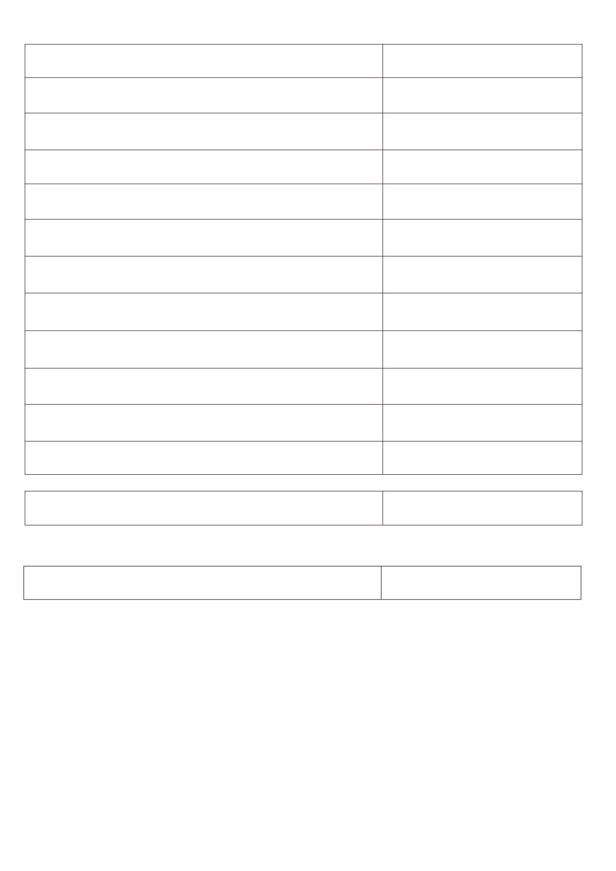
FC - 38 Simple PLC section 10 operation time
0.0s(h)~6500.0s(h)【0.0s(h)】
FC - 39 Simple PLC 10th acceleration and deceleration time
0~3【0】
FC - 40 Simple PLC section 11 operating time
0.0s(h)~6500.0s(h)【0.0s(h)】
FC - 41 Simple PLC section 11 acceleration and deceleration time
0~3【0】
FC - 42 Simple PLC section 12 operation time
0.0s(h)~6500.0s(h)【0.0s(h)】
FC - 43 Simple PLC section 12 acceleration and deceleration time
0~3【0】
FC - 44 Simple PLC section 13 operating time
0.0s(h)~6500.0s(h)【0.0s(h)】
FC - 45 Simple PLC section 13 acceleration and deceleration time
0~3【0】
FC - 46 Simple PLC section 14 operating time
0.0s(h)~6500.0s(h)【0.0s(h)】
FC - 47 Simple PLC section 14 acceleration and deceleration time
0~3【0】
FC - 48 Simple PLC section 15 operating time
0.0s(h)~6500.0s(h)【0.0s(h)】
FC - 49 Simple PLC section 15 acceleration and deceleration time
0~3【0】
FC - 50 Simple PLC running time unit
0~1【0】
0: S (seconds)
1: h (hours)
FC - 51 multi-segment instruction 0 given mode
0~6【0】
0: Given function code FC - 00
1: AI1
2: AI2
3: AI3
4: X5 pulse input.
5: PID.
6: Given the preset frequency (F0 - 09), up / down can be modified.
119
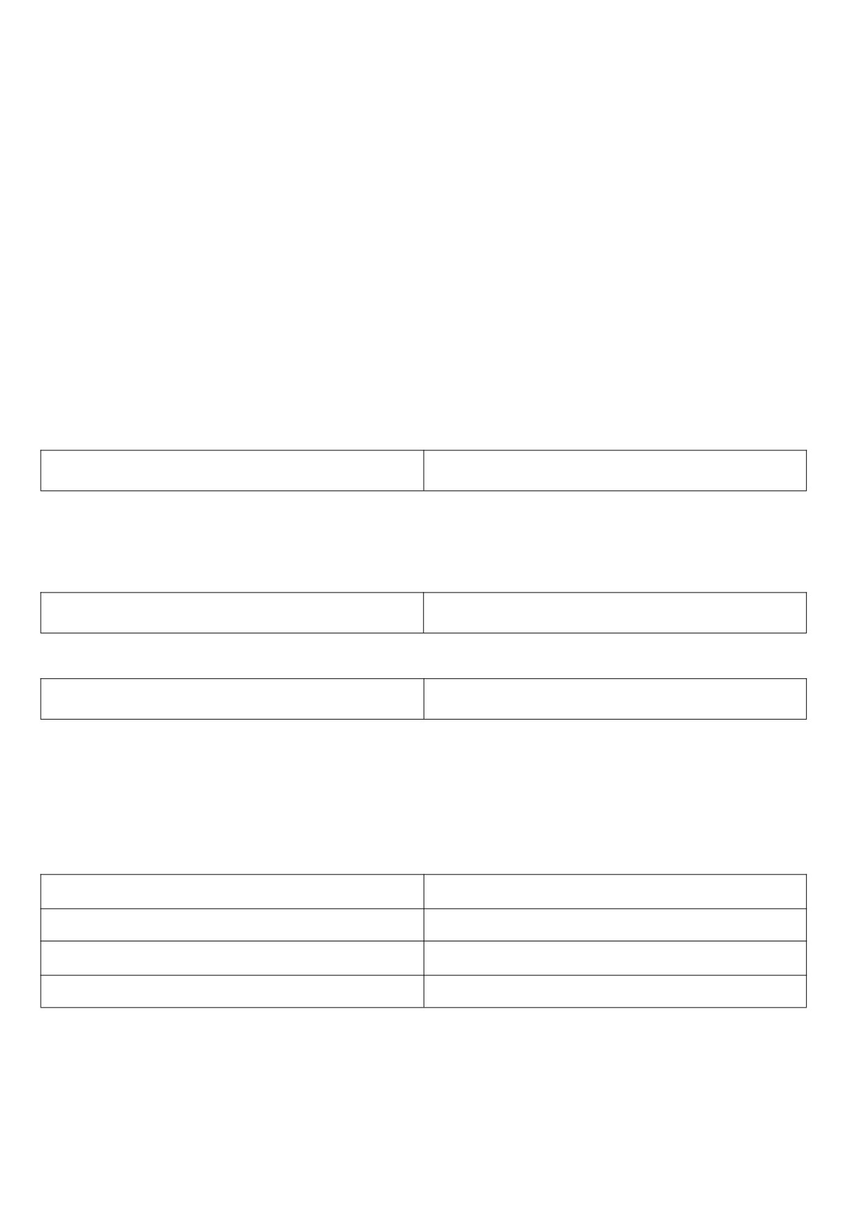
FD Group communication parameters
Please refer to appendix a: description of communication parameters of FD group.
FE Group user-defined function code
This group function code is a user-defined parameter group.
The user can select the required parameters from all HV610 function codes and summarize them to the Fe
group as user-customized parameters.
Number to facilitate viewing and changing operations The Fe group provides up to 30 user-defined parameters,
and the displayed value of the Fe group parameter is f 0.00, which indicates the user function code is empty.
When entering the user-defined parameter mode, the display function codes are defined by FE-00~FE-31. The
order is the same as that of the FE group function codes. If F0 - 00, it will be skipped.
FF Group control optimization parameters
FF - 04
cbc current limiting enable
0~1【0】
0: not enabled.
1: enabling wave-by-wave current limiting.
By enabling the wave-by-wave current limiting function, the over-current fault of the frequency inverter can be
minimized and the frequency inverter can be guaranteed to run uninterruptedly.
FF - 06
Uder voltage point setting
60%~140%【100.0%】
Voltage value of frequency inverter under voltage fault LV
FF - 09
over voltage point setting
200.0V~2200.0V【820.0V】
Note: the factory value is also the upper limit value of the internal over voltage protection of the frequency
inverter. This parameter setting will only take effect if the FF - 09 setting value is less than the factory value. If it is
higher than the factory value, the factory value shall prevail.
E0 Group fault record
E0-00
First failure type
0~99【0】
E0-01
Second failure type
0~99【0】
E0-02
Third ( most recent ) fault type
0~99【0】
E0-03
Frequency at third failure
0.00~500.00【0.00HZ】
120
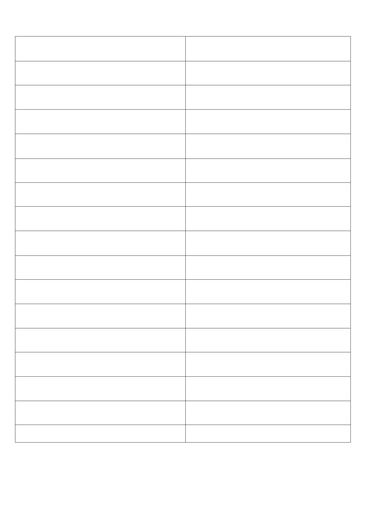
E0 - 04
Current at third fault
0.00~500.00【0.00A】
E0 - 05
Bus voltage at the third fault
0.0~2000.0【0.0V】
E0 - 08
Frequency inverter status at third failure
0~65535【0】
E0 - 09
Power-on time for third failure
0~65535【0】
E0 - 10
Run time at third failure
0~65535【0】
E0 - 13
Frequency at second failure
0.00~500.00【0.00HZ】
E0 - 14
Current at second failure
0.00~500.00【0.00A】
E0 - 15
Bus voltage at second failure
0.0~2000.0【0.0V】
E0 - 18
Frequency inverter status at second failure
0~65535【0】
E0 - 19
Power-on time for second failure
0~65535【0】
E0 - 20
Run time at second failure
0~65535【0】
E0 - 23
Frequency at first failure
0.00~500.00【0.00HZ】
E0 - 24
Current at first failure
0.00~500.00【0.00A】
E0 - 25
Bus voltage at first failure
0.0~2000.0【0.0V】
E0 - 28
Frequency inverter status at first failure
0~65535【0】
E0 - 29
Power-on time for first failure
0~65535【0】
E0 - 30
Run time at first failure
0~65535【0】
121
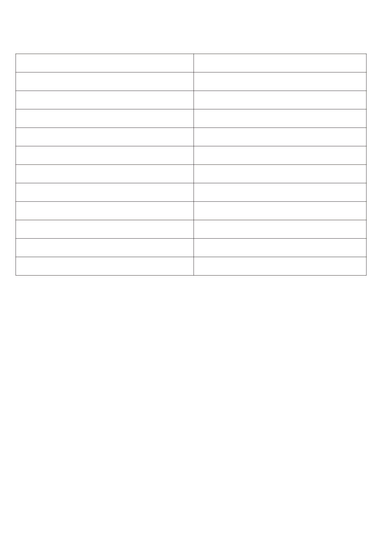
P2 Group AIAO correction
P2 - 00
A I1 measured voltage 1
-10.000V~10.000V【2.000V】
P2 - 01
A I1 shows voltage 1
-10.000V~10.000V【2.000V】
P2 - 02
A I1 measured voltage 2
-10.000V~10.000V【8.000V】
P2 - 03
AI1 shows voltage 2
-10.000V~10.000V【8.000V】
P2 - 04
AI2 measured voltage 1
-10.000V~10.000V【2.000V】
P2 - 05
AI2 shows voltage 1
-10.000V~10.000V【2.000V】
P2 - 06
AI2 measured voltage 2
-10.000V~10.000V【8.000V】
P2 - 07
AI2 shows voltage 2
-10.000V~10.000V【8.000V】
P2 - 08
AI3 measured voltage 1
-10.000V~10.000V【2.000V】
P2 - 09
AI3 shows voltage 1
-10.000V~10.000V【2.000V】
P2 - 10
AI3 measured voltage 2
-10.000V~10.000V【8.000V】
P2 - 11
AI3 shows voltage 2
-10.000V~10.000V【8.000V】
The set of function codes is used to correct the analog quantity input AI to eliminate the influence of zero offset
and gain at the AI input.
The set of functional parameters has been corrected at the factory. When the factory value is restored, it will be
restored to the factory corrected value.Generally, no correction is required at the application site.
Measured voltage refers to the actual voltage measured by measuring instruments such as multimeter.
Display voltage refers to the voltage display value sampled by the frequency converter. See u0 group ai
pre-correction voltages (U0 - 21, U0 - 22, U0 - 23) for display.
During correction, two voltage values are input to each AI input port, and the values measured by the multimeter
and the values read by the U0 group are input into the above function codes accurately, then the frequency converter
will automatically correct the zero offset and gain of AI.
For the situation where the voltage given does not match the actual sample voltage of the frequency converter, a
field correction method can be adopted so that the sampling value of the frequency convert is consistent with the
expected given value.
122
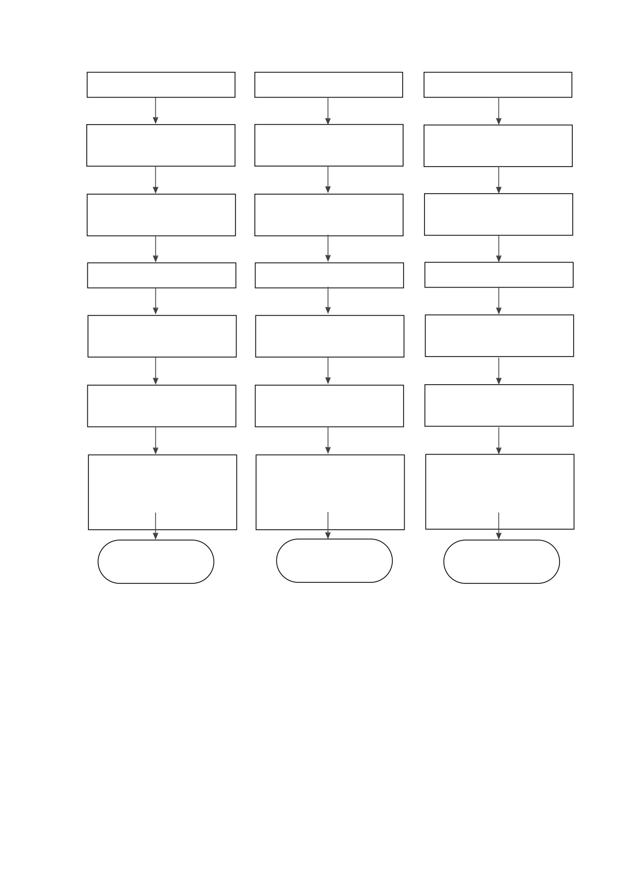
Given AI1 voltage signal (2v or so)
Given AI2 voltage signal (2v or so)
Given AI3 voltage signal (2v or so)
Measured actual measured AI1
Measured actual measured AI2
Measured actual measured AI3
voltage value is recorded as v1
voltage value is recorded as v1
voltage value is recorded as v1
View U0 - 21 display value record as
View U0 - 22 display value record as
View U0 - 23 display value record as
u1
u1
u1
Given AI1 voltage signal (8v or so)
Given AI2 voltage signal (8v or so)
Given AI3 voltage signal (8v or so)
Measured actual measured AI1
Measured actual measured AI2
Measured actual measured AI3
voltage value is recorded as v2
voltage value is recorded as v2
voltage value is recorded as v2
View U0 - 21 display value record as
View U0 - 22 display value record as
View U0 - 23 display value record as
U2
U2
U2
V1 input P2 - 00
V1 input P2 - 04
V1 input P2 - 08
u1 input P2 - 01
u1 input P2 - 05
u1 input P2 - 09
v2 input P2 - 02
v2 input P2 - 06
v2 input P2 - 10
u2 input P2 - 03
u2 input P2 - 07
u2 input P2 - 11
AI1 calibration completed
AI2 calibration completed
AI3 calibration completed
Figure 5 - 34 AI calibration method diagram
123
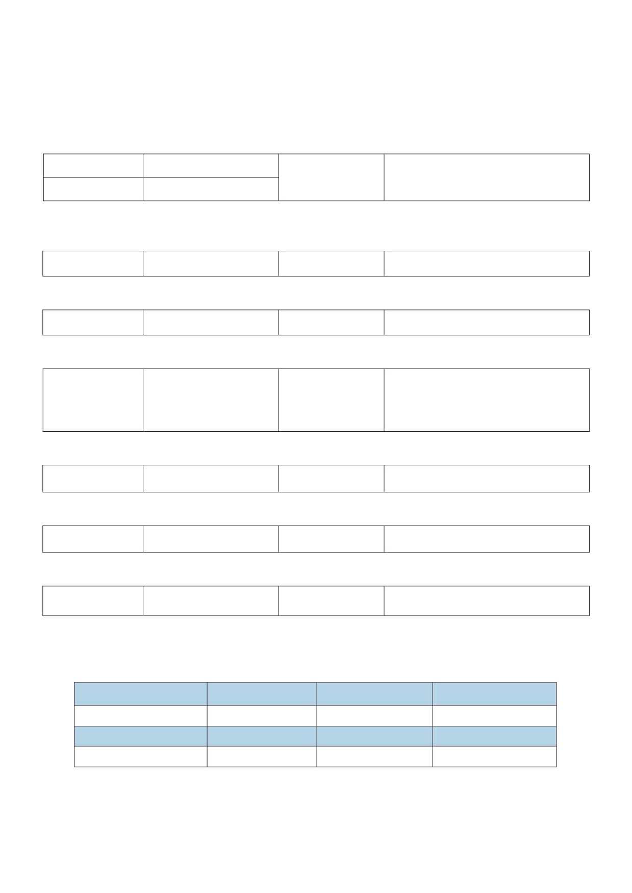
U0 Group monitoring parameter group
The U0 parameter group is used to monitor the operation status information of the frequency inverter.
Customers can check it through the panel to facilitate on-site commissioning. They can also read the parameter
group values through communication for monitoring by the upper computer. The communication address is 0x7000
~
0x7044.
U0-00
Running frequency
Indication range
0.00:500.00Hz
U0-01
Set frequency
Display the absolute values of the theoretical operating frequency and the set frequency of the frequency inverter.
See U0 - 19 for actual output frequency of frequency inverter.
U0-02
Busbar voltage
Indication range
0.0V~3000.0V
Display the inverter bus voltage value.
U0-03
Output voltage
Indication range
0V~1140V
Display the output voltage value of the frequency inverter during operation.
0.00A~655.35A
U0-04
Output current
Indication range
(frequency inverter power < = 55kw )
0.0A~6553.5A
(frequency inverter power > 55kw )
Display the output current value of the frequency inverter during operation.
U0-05
Output power
Indication range
0~32767
Display the output power value of the frequency inverter during operation.
U0-06
Output torque
Indication range
-200.0%
- 200.0%
Display the output torque value of the frequency inverter during operation.
U0-07
X terminal input status
Indication range
0~32767
Display the current X terminal input status value. After being converted into binary data, each bit corresponds to
X input signal, a value of 1 indicates that the input is a high level signal, and a value of 0 indicates that the input is a
low level signal. The correspondence between each bit and the input terminal is as follows:
Bit0
Bit1
Bit2
Bit3
X1
X2
X3
X4
Bit4
Bit5
Bit6
X5
X6
X7
124
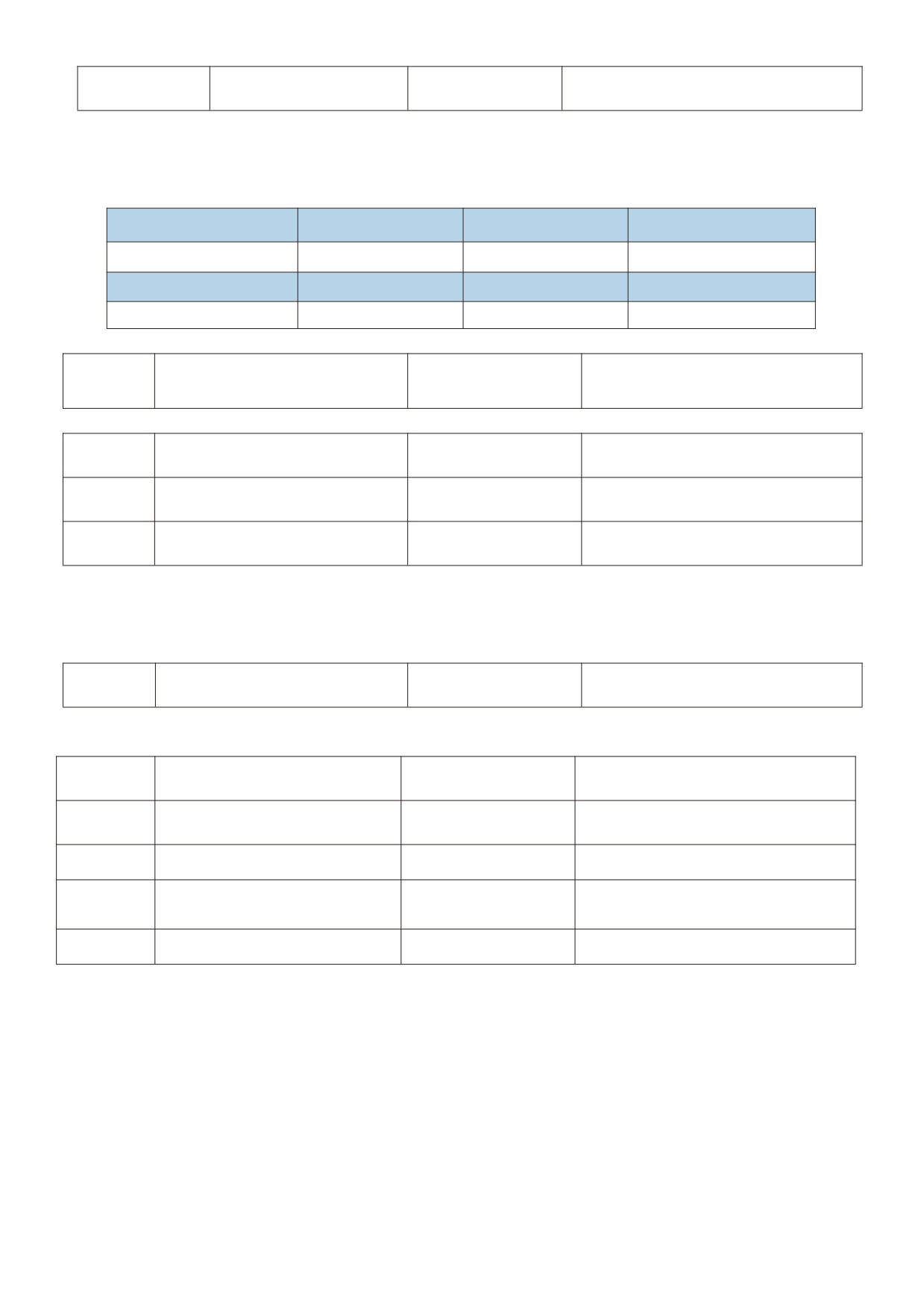
U0-08
Do output state
Indication range
0~1023
Display the current DO terminal output status value. After being converted into binary data, each bit corresponds
to a DO signal, indicating the output high level for 1 and the output low level for 0. The correspondence between
each bit and the output terminal is as follows:
Bit1
Bit3
Relay 1
DO1
Bit4
DO2
0.00V~10.57V
U0-10
AI2 voltage ( v ) / current ( mA )
Indication range
0.00mA~20.00mA
U0-14
Load speed display
Indication range
0~65535
U0-15
PID setting
Indication range
0~65535
U0-16
PID feedback
Indication range
0~65535
Display the PID setting value and feedback value. The value format is as follows:
PID setting = PID setting (percentage) * FA - 04
PID feedback = PID feedback (percentage) * FA - 04.
U0-18
PULSE input pulse frequency
Indication range
0.00kHz~100.00KHz
Display X5 high speed pulse sampling frequency, minimum unit is 0.01 KHz.
U0-19
Feedback speed
Indication range
-320.00Hz~320.00Hz
U0-20
Remaining operating time
Indication range
0.0~6500.0 minutes
U0-21
AI1 pre-correction voltage
Indication range
0.000V~10.570V
AI2 voltage / current before
0.000V~10.570V
U0-22
Indication range
correction
0.000mA~20.000mA
U0-23
AI3 voltage before correction
Indication range
-10.570V~10.570V
Display the actual value of the analog input sample voltage / current.
The voltage / current actually used has been linearly corrected so that the sampled voltage / current is in line with the
actual input voltage / electricityThe flow deviation is smaller.
See U0 - 09, U0 - 10, U0 - 11 for the correction voltage / current actually used, and P3 group for the correction
method.
125
U0-24
Linear velocity
Indication range
0 ~ 65535 m / min
U0-27
PULSE input pulse frequency
Indication range
0:65535Hz
Display X5 high speed pulse sampling frequency in 1hz. It is the same data as u0 - 18, only showing different units.
U0-28
communication settings value
Indication range
communication settings value
Display data written through address 0x1000.
U0-30
Main frequency X display
Indication range
0.00Hz~500.00Hz
Display the main frequency source X frequency setting.
U0-31
Auxiliary frequency Y display
Indication range
0.00Hz~500.00Hz
Display the auxiliary frequency Y frequency setting.
U0-35
Target torque
Indication range
200.0%
- 200.0%
Display the current torque upper limit setting.
U0-37
Power factor angle
Indication range
-
Display the current operating power factor angle.
U0-39
VF separates target voltage
Indication range
0v ~ rated voltage of motor
U0-40
VF separates output voltage
Indication range
0v ~ rated voltage of motor
Display the target output voltage and the current actual output voltage when operating in the VF separation state.
VF separation is described in F3 group.
X7 X5 X3 X1
- light for valid
U0-41
X input status visual display
Indication range
extinction is not
invalid
X6 X4 X2
126
U0-42
Do output status visual display
Indication range
-
U0-59
Set frequency
Indication range
-100.00%
- 100.00%
U0-60
Running frequency
Indication range
-100.00%
- 100.00%
Display the current set frequency and operating frequency. 100.00 % corresponds to the maximum frequency of
the frequency inverter (F0 - 16).
Operating state of frequency
U0-61
Indication range
0~65535
inverter
Display the frequency inverter operation status information.
The data definition format is as follows:
Bit0
0: shutdown;
1: forward rotation;
2: reversal
Bit1
U0-61
Bit2
0: constant speed;
1: accelerating;
2: slow down
Bit3
Bit4
0: bus voltage is normal;
1: under voltage
U0-62
Current fault code
Indication range
0~99
Display the current fault code.
U0-65
Upper torque limit
Indication range
-200.00%
- 200.00%
Display the current upper limit of the given torque.
Frequency inverter module
U0-69
Indication range
0℃~120℃
radiator temperature
Display the temperature of the frequency inverter module IGBT.
The over-temperature protection values of IGBT modules of different models are different.
127
U0-70
Accumulated operating time
Indication range
0~65536h
U0-71
Cumulative power-on time
Indication range
0~65536h
U0-72
Cumulative power consumption
Indication range
0 ~ 65535 degrees
U0-73
Product Number
Indication range
-
U0-74
Software version number
Indication range
-
U0-76
Rated power of frequency converter
Indication range
-
U0-77
Frequency inverter G/P type machine
Indication range
-
U0-78
Rated voltage of frequency inverter
Indication range
-
128

Chapter VI Abnormal diagnosis
6.1 Fault alarm and countermeasures
Countermeasures for fault
Sr. No.
Fault name
Operation panel display
Troubleshooting of cause of failure
handling
1. Eliminate peripheral faults
1. Frequency inverter output circuit short
2. Install reactors or output
circuit
filters
2. Motor and frequency inverter wiring is
3. Check whether the air duct
too long
is blocked, fan is it working
Frequency inverter
3. Module overheating
01
properly and excluded
unit protection
4. The internal wiring of the frequency
question
inverter is loose
4. Plug in all connection lines
5. Abnormal main control board
5. Seek technical support
6. Abnormal drive plate
6. Seek technical support
7. Abnormal frequency inverter module
7. Seek technical support
1. Eliminate peripheral faults
2. Identify motor parameters
1. Frequency inverter output circuit is
3. Increase the acceleration
connected ground or short circuit
time
2. The control mode is vector and no
4. Adjust the manual lifting
parameter identification is carried out
torque or V/F curve
3. The acceleration time is too short
5. Adjust the voltage to the
Accelerated over
4. Manual torque increase or V/F curve
normal range
02
current
is not appropriate
6. Choose speed tracking start
5. Iow voltage
or wait for the electric
6. Start the rotating motor
machine to stop before
7. Sudden loading during acceleration
starting
8. The selection of frequency inverter is
7. Cancel the sudden load
small
8. Choose the frequency
inverter with higher power
level
1. Frequency inverter output circuit is
connected ground or short circuit
1. Eliminate peripheral faults
2. The control mode is vector and no
2. Identify motor parameters
parameter identification is carried out
3. Increase the deceleration
Deceleration over
3. The deceleration time is too short
time
03
current
4. Low voltage
4. Adjust the voltage to the
5. Sudden load increase during
normal range
deceleration
5. Cancel the sudden load
6. No brake unit and system added
6. Add brake unit and resistor
dynamic resistance
1. Frequency inverter output circuit is
connected ground or short circuit
1. Eliminate peripheral faults
2. The control mode is vector and there
2. Identify motor parameters
is no carry out parameter
3. Adjust the voltage to the
Constant speed
identification
normal range
04
over current
3. Low voltage
4. Cancel the sudden load
4. Whether there is a sudden load in
5. Choose the frequency
operation
inverter with higher power
5. The selection of frequency inverter is
level
small
129
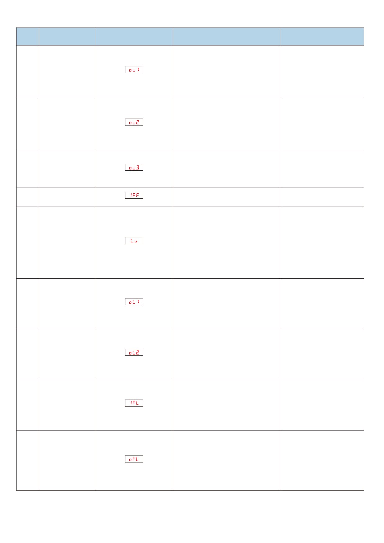
Countermeasures for fault
Sr. No.
Fault name
Operation panel display
Troubleshooting of cause of failure
handling
1. Adjust the voltage to the
1. High input voltage
normal range
2. There is an external force to drag the
2 Cancel the power or add
Accelerating over
motor to run during acceleration
05
brake resistance
voltage
3. The acceleration time is too short
3. Increase the acceleration
4. No brake unit and brake resistor are
time
installed
4. Add brake unit and resistor
1. Adjust the voltage to the
1. High input voltage
normal range
2. There is an external force to drag the
2 Cancel the power or add
Deceleration over
motor to run during deceleration
06
brake resistance
voltage
3. The deceleration time is too short
3. Increase the deceleration
4. No brake unit and brake resistor are
time
installed
4. Add brake unit and resistor
1. Adjust the voltage to the
1. High input voltage
Constant speed
normal range
07
2. There is external drag during
over voltage
2. Cancel the power or add
operation moving motor operation
brake resistance
Control power
1. The input voltage is not within the
1. Adjust the voltage to the
08
failure
scope of the specification
standard range
1. Instantaneous power failure
2. Frequency inverter input terminal
1. Reset fault
voltage is not within the scope of the
2. Adjust the voltage to the
specification requirements
normal range
09
Under voltage fault
3. Bus voltage is not normal
3. Seek technical support
4. Rectifier bridge and buffer resistance
4. Seek technical support
is not normal
5. Seek technical support
5. Abnormal drive plate
6. Seek technical support
6. Abnormal control panel
1. Reduce the load and check
1. Whether the load is too large or
the motor and machine
electricity occurs locked rotation of
frequency inverter
mechanical situation
10
machine
overload
2. Choose the frequency
2. The selection of frequency inverter is
inverter with higher power
small
level
1. Is the setting of motor protection
1. Set this parameter correctly
parameter F9 - 01 appropriate
2. Reduce the load and check
2. Whether the load is too large or the
the motor and machinery
11
Motor overload
electric machine is blocked
3. Choose the frequency
3. The selection of frequency inverter is
inverter with higher power
small
level
1. Check and eliminate
1. Three-phase input power supply is
problems existing in
not normal
peripheral lines
12
Input phase missing
2. Abnormal drive plate
2. Seek technical support
3. Abnormal lightning protection plate
3. Seek technical support
4. Abnormal main control board
4. Seek technical support
1. The lead from the frequency inverter
1. Eliminate peripheral faults
to the motor is not normal
2, Check whether the motor
2. The three-phase output of the
Output phase
three-phase winding is
13
frequency inverter is unbalanced
missing
normal and troubleshooting
when the motor is running
3. Seek technical support
3. Abnormal drive plate
4. Seek technical support
4. Module exception
130