HV610C Series Frequency Inverter. User Manual (Version: 3.1.14) - page 7
Appendix II Parameter Settings List
F5.12
AO2 zero offset
0.00%
F5.13
AO2 gain
1.00
F5.17
Y1R output delay time
0.0s
F5.18
RELAY1 output delay time
0.0s
F5.19
RELAY2 output delay time
0.0s
F5.20
DO1 output delay time
0.0s
F5.21
DO2 output delay time
0.0s
F5.22
DO output terminal valid state selection
00000
F6
Start/stop control: F6.00-F6.15
F6.00
Start mode
0
F6.01
Revolving speed tracking mode
0
F6.02
Revolving speed tracking speed
20
F6.03
Start frequency
0.00Hz
F6.04
Start frequency holding time
0.0s
F6.05
Start dc braking current /pre-excitation current
0%
F6.06
Start dc braking time /pre-excitation time
0.0s
F6.07
Acceleration/deceleration mode
0
F6.08
S-curve initial-segment time proportion
30.0%
F6.09
S-curve end-segment time proportion
30.0%
F6.10
Stop mode
0
F6.11
DC braking initial frequency at stop
0.00Hz
F6.12
DC braking waiting time at stop
0.0s
F6.13
DC braking current at stop
0%
F6.14
DC braking time at stop
0.0s
F6.15
Brake utilization ratio
100%
F7
Keyboard and display: F7.00-F7.14
F7.01
MF/REV key function selection
0
F7.02
STOP/RESET function
1
F7.03
LED running display parameter 1
1F
F7.04
LED running display parameter 2
0
F7.05
LED stop display parameter
0
F7.06
Load speed coefficient
1.0000
F7.07
Inverter module radiator temperature
F7.08
product ID
140
Appendix II Parameter Settings List
F7.09
Accumulative running time
0h
F7.10
Performance version number
-
F7.11
Software version No.
-
F7.12
Load speed display decimal digits
1
F7.13
Accumulative power-on time
-
F7.14
Accumulative power consumption
-
F8
Auxiliary Function: F8.00-F8.53
F8.00
Jog running frequency
2.00Hz
F8.01
Jog acceleration time
20.0s
F8.02
Jog deceleration time
20.0s
F8.03
Acceleration time 2
10.0s
F8.04
Deceleration time 2
10.0s
F8.05
Acceleration time 3
10.0s
F8.06
Deceleration time 3
10.0s
F8.07
Acceleration time 4
10.0s
F8.08
Deceleration time 4
10.0s
F8.09
Hopping frequency 1
0.00Hz
F8.10
Hopping frequency 2
0.00Hz
F8.11
Hopping frequency amplitude
0.00Hz
F8.12
Dead zone time of forward & reverse rotations
0.0s
F8.13
Reverse rotation control
0
F8.14
Set frequency below lower limit running mode
0
F8.15
Droop control
0.00Hz
F8.16
Accumulative power-on time arrival setup
0h
F8.17
Accumulative running time arrival setup
0h
F8.18
Start protection selection
0
F8.19
Frequency detection value (FDT1)
50.00Hz
F8.20
Frequency detection hysteresis value (FDT1)
5.0%
F8.21
Frequency arrival detection amplitude
0.0%
F8.22
Acc./dec. hopping frequency validity
0
F8.25
Acc. time1 & acc. time 2 frequency switching point
0.00Hz
F8.26
Dec. time1 & dec. time 2 frequency switching point
0.00Hz
F8.27
Terminal jog priority
0
F8.28
Frequency detection value(FDT2)
50.00Hz
141
Appendix II Parameter Settings List
F8.29
Frequency detection hysteresis value(FDT2)
5.0%
F8.30
Random frequency arrival detection value1
50.00Hz
F8.31
Random frequency arrival detection range1
0.0%
F8.32
Random frequency arrival detection value2
50.00Hz
F8.33
Random frequency arrival detection range2
0.0%
F8.34
Zero-current detection level
5.0%
F8.35
Zero-current detection delay time
0.10s
F8.36
Output current overlimit value
200.0%
F8.37
Output current overlimit detection delay time
0.00s
F8.38
Random current arrival 1
100.0%
F8.39
Random current arrival range1
0.0%
F8.40
Random current arrival 2
100.0%
F8.41
Random current arrival range2
0.0%
F8.42
Timing function selection
0
F8.43
Running time timing selection
0
F8.44
Timing running time
0.0Min
F8.45
AI1 input voltage protection value lower limit
3.10V
6.80V
F8.46
AI1 input voltage protection value upper limit
F8.47
Module temperature arrival
75℃
F8.48
Cooling fan control
0
F8.49
Wake-up frequency
0.00Hz
F8.50
Wake-up delay time
0.0s
F8.51
Sleep frequency
0.00Hz
F8.52
Sleep delay time
0.0s
F8.53
The running time arrival
0.0Min
F9
Overload and Protection: F9.00-F9.70
F9.00
Motor overload protection selection
1
F9.01
Motor overload protection gain
1.00
F9.02
Motor overload pre-alarm coefficient
80%
F9.03
Over-voltage stall gain
0
F9.04
Over-voltage stall protection voltage
130%
F9.05
Over current stall gain
20
F9.06
Over current stall protection current
150%
142
Appendix II Parameter Settings List
F9.07
Ground short circuit protection upon power-on
1
F9.09
Fault auto reset times
0
F9.10
Fault auto reset FAULT DO selection
0
F9.11
Fault auto reset interval
1.0s
F9.12
Input phase lack protection selection
11
F9.13
Output phase lack protection selection
1
F9.14
The first fault type
-
F9.15
The second fault type
-
F9.16
The latest fault type
-
F9.17
Third fault frequency
-
F9.18
Third fault current
-
F9.19
Third fault bus voltage
-
F9.20
Third fault input terminal
-
F9.21
Third fault output terminal
-
F9.22
Third fault inverter state
-
F9.23
Third fault power-on time
-
F9.24
Third fault running time
-
F9.27
Second fault frequency
-
F9.28
Second fault current
-
F9.29
Second fault bus voltage
-
F9.30
Second fault input terminal
-
F9.31
Second fault output terminal
-
F9.32
Second fault inverter state
-
F9.33
Second fault power-on time
-
F9.34
Second fault running time
-
F9.37
First fault frequency
-
F9.38
First fault current
-
F9.39
First fault bus voltage
-
F9.40
First fault input terminal
-
F9.41
First fault output terminal
-
F9.42
First fault inverter state
-
F9.43
First fault power-on time
-
F9.44
First fault running time
-
F9.47
Fault protection action selection 1
00000
143
Appendix II Parameter Settings List
F9.48
Fault protection action selection 2
00000
F9.49
Fault protection action selection 3
00000
F9.50
Fault protection action selection 4
00000
F9.54
Continued to run when fault frequency selection
0
F9.55
Abnormal backup frequency
100.0%
F9.56
Motor temperature sensor
0
F9.57
Motor overheating protection threshold
110℃
F9.58
Motor overheating pre-alarm threshold
90℃
F9.59
Transient stop selection
0
F9.60
Transient stop action pause protection voltage
90.0%
F9.61
Transient stop voltage recovery judgment time
0.50s
F9.62
Transient stop action judgment voltage
80.0%
F9.63
Load-off protection selection
0
F9.64
Load-off detection level
10.0%
F9.65
Load-off detection time
1.0s
F9.67
Over speed detection value
20.0%
F9.68
Over speed detection time
1.0s
F9.69
Excessive speed deviation detection value
20.0%
F9.70
Excessive speed deviation detection time
5.0s
FA
PID Function group: FA.00-FA.28
FA.00
PID reference source
0
FA.01
PID reference value
50.0%
FA.02
PID feedback source
0
FA.03
PID action direction
0
FA.04
PID reference feedback range
1000
FA.05
Proportional gain KF1
20.0
FA.06
Integration time Ti1
2.00s
FA.07
Differential time Td1
0.000s
FA.08
PID cutoff frequency of reverse rotation
2.00Hz
FA.09
PID deviation limit
0.0%
FA.10
PID differential amplitude limit
0.10%
FA.11
PID reference change duration
0.00s
FA.12
PID feedback filter time
0.00s
FA.13
PID output filter time
0.00s
144
Appendix II Parameter Settings List
FA.14
Reserved
-
FA.15
Proportional gain KF2
20.0
FA.16
Integration time Ti2
2.00s
FA.17
Differential time Td2
0.000s
FA.18
PID parameter switching condition
0
FA.19 PID parameter switching deviation1
20.0%
FA.20 PID parameter switching deviation2
80.0%
FA.21
PID initial value
0.0%
FA.22
PID initial value retention time
0.00s
FA.23
Output deviation forward maximum value
1.00%
FA.24
Output deviation reverse maximum value
1.00%
FA.25
PID integration attribute
00
FA.26
PID feedback loss detection value
0.0%
FA.27
PID feedback loss detection time
0s
FA.28
PID stop operation
0
Fb
Swing Frequency, Fixed Length and Counting: Fb.00-Fb.09
Fb.00
Swing setup mode
0
Fb.01
Swing frequency amplitude
0.0%
Fb.02
Jump frequency amplitude
0.0%
Fb.03
Swing frequency cycle
10.0s
Fb.04
Triangle wave rise time coefficient
50.0%
Fb.05
Setup length
1000m
Fb.06
Actual length
0m
Fb.07
Pulse number per meter
100.0
Fb.08
Counting value setup
1000
Fb.09
Designated counting value
1000
FC
MS Speed Function & Simple PLC Function: FC.00-FC.51
FC.00
MS command 0
0.0%
FC.01
MS command 1
0.0%
FC.02
MS command 2
0.0%
FC.03
MS command 3
0.0%
FC.04
MS command 4
0.0%
FC.05
MS command 5
0.0%
145
Appendix II Parameter Settings List
FC.06
MS command 6
0.0%
FC.07
MS command 7
0.0%
FC.08
MS command 8
0.0%
FC.09
MS command 9
0.0%
FC.10
MS command 10
0.0%
FC.11
MS command 11
0.0%
FC.12
MS command 12
0.0%
FC.13
MS command 13
0.0%
FC.14
MS command 14
0.0%
FC.15
MS command 15
0.0%
FC.16
PLC running mode
0
FC.17
PLC power off memory selection
00
FC.18
PLC 0segment running time
0.0s(h)
FC.19
PLC 0segment acc./dec. time
0
FC.20
PLC 1segment running time
0.0s(h)
FC.21
PLC 1segment acc./dec. time
0
FC.22
PLC 2 segment running time
0.0s(h)
FC.23
PLC 2 segment acc./dec. time
0
FC.24
PLC 3 segment running time
0.0s(h)
FC.25
PLC 3 segment acc./dec. time
0
FC.26
PLC 4 segment running time
0.0s(h)
FC.27
PLC 4 segment acc./dec. time
0
FC.28
PLC 5 segment running time
0.0s(h)
FC.29
PLC 5 segment acc./dec. time
0
FC.30
PLC 6 segment running time
0.0s(h)
FC.31
PLC 6 segment acc./dec. time
0
FC.32
PLC 7 segment running time
0.0s(h)
FC.33
PLC 7 segment acc./dec. time
0
FC.34
PLC 8 segment running time
0.0s(h)
FC.35
PLC 8 segment acc./dec. time
0
FC.36
PLC 9 segment running time
0.0s(h)
FC.37
PLC 9 segment acc./dec. time
0
FC.38
PLC 10 segment running time
0.0s(h)
146
Appendix II Parameter Settings List
FC.39
PLC 10 segment acc./dec. time
0
FC.40
PLC 11 segment running time
0.0s(h)
FC.41
PLC 11 segment acc./dec. time
0
FC.42
PLC 12 segment running time
0.0s(h)
FC.43
PLC 12 segment acc./dec. time
0
FC.44
PLC 13 segment running time
0.0s(h)
FC.45
PLC 13 segment acc./dec. time
0
FC.46
PLC 14 segment running time
0.0s(h)
FC.47
PLC 14 segment acc./dec. time
0
FC.48
PLC 15 segment running time
0.0s(h)
FC.49
PLC 15 segment acc./dec. time
0
FC.50
Running time unit
0
FC.51
MS command 0 reference mode
0
Fd
Communication function group:Fd.00-Fd.29
Fd.00
Baud rate
6005
Fd.01
Data format
0
Fd.02
Local address
1
Fd.03
Response delay
2
Fd.04
Excessive communication time
0.0
Fd.05
Data transformat selection
30
Fd.06
Communication read current resolution
0
FE
User customization function code: FE.00-FE.29
FE.00
User function code 0
F0.01
FE.01
User function code 1
F0.02
FE.02
User function code 2
F0.03
FE.03
User function code 3
F0.07
FE.04
User function code 4
F0.08
FE.05
User function code 5
F0.17
FE.06
User function code 6
F0.18
FE.07
User function code 7
F3.00
FE.08
User function code 8
F3.01
FE.09
User function code 9
F4.00
FE.10
User function code 10
F4.01
147
Appendix II Parameter Settings List
FE.11
User function code 11
F4.02
FE.12
User function code 12
F5.04
FE.13
User function code 13
F5.07
FE.14
User function code 14
F6.00
FE.15
User function code 15
F6.10
FE.16
User function code 16
F0.00
FE.17
User function code 17
F0.00
FE.18
User function code 18
F0.00
FE.19
User function code 19
F0.00
FE.20
User function code 20
F0.00
FE.21
User function code 21
F0.00
FE.22
User function code 22
F0.00
FE.23
User function code 23
F0.00
FE.24
User function code 24
F0.00
FE.25
User function code 25
F0.00
FE.26
User function code 26
F0.00
FE.27
User function code 27
F0.00
FE.28
User function code 28
F0.00
FE.29
User function code 29
F0.00
FP
Function code management:FP.00-FP.04
FP.00
User password
0
FP.01
Parameter initialization
0
FP.02
Parameter display attribute
11
FP.03
Personalized parameter display selection
00
FP.04
Function codes modification attribute
0
A0
Torque control group: A0.00-A0.08
A0.00
Speed/ torque control mode selection
0
A0.01
Torque setup source selection in torque control mode
0
A0.03
Torque digital setup in torque control mode
150%
A0.05
Torque control forward maximum frequency
50.00Hz
A0.06
Torque control reverse maximum frequency
50.00Hz
A0.07
Torque control acc. time
0.00s
A0.08
Torque control dec. time
0.00s
148
Appendix II Parameter Settings List
A1
Virtual IO: A1.00-A1.21
A1.00
Virtual VX1 function selection
0
A1.01
Virtual VX2 function selection
0
A1.02
Virtual VX3 function selection
0
A1.03
Virtual VX4 function selection
0
A1.04
Virtual VX5 function selection
0
A1.05
Virtual VD1 terminal valid state set mode
00000
A1.06
Virtual VD1 terminal state
00000
A1.07
AI1 as X function selection
0
A1.08
AI2 as X function selection
0
A1.09
AI3 as X function selection
0
A1.10
AI as X valid mode selection
000
A1.11
Virtual VDO1 output function
0
A1.12
Virtual VDO2 output function
0
A1.13
Virtual VDO3 output function
0
A1.14
Virtual VDO4 output function
0
A1.15
Virtual VDO5 output function
0
A1.16
VDO1 output delay time
0.0s
A1.17
VDO2 output delay time
0.0s
A1.18
VDO3 output delay time
0.0s
A1.19
VDO4 output delay time
0.0s
A1.20
VDO5 output delay time
0.0s
A1.21
VDO output terminal valid state selection
00000
A2
The second motor control: A2.00-A2.65
A2.00
Motor type selection
0
A2.01
Rated power
-
A2.02
Rated voltage
-
A2.03
Rated current
-
A2.04
Rated frequency
-
A2.05
Rated revolving speed
-
A2.06
Asynchronous motor stator resistance
-
A2.07
Asynchronous motor rotor resistance
-
A2.08
Asynchronous motor leakage inductance
-
149
Appendix II Parameter Settings List
A2.09
Asynchronous motor mutual inductance
-
A2.10
Asynchronous motor no load current
-
A2.16
Synchronous motor stator resistance
-
A2.17
Synchronous motor D-axis inductance
-
A2.18
Synchronous motor Q-axis inductance
-
Synchronous motor
A2.19
0
inductance resistance unit
Synchronous motor back electromotive force
A2.20
0.1V
coefficient.
Synchronous motor output phase lack detection
A2.21
0
time
A2.27
Encoder pulses number
2500
A2.28
Encoder type
0
A2.29
Speed feedback PG selection
0
A2.30
ABZ incremental encoder AB phase
0
A2.31
Encoder installation angle
0
A2.32
UVW phase sequence
0
A2.33
UVW encoder offset angle
0.00
A2.34
Rotary transformer pole pairs
1
A2.35
UVW pole-pairs
4
A2.36
PG dropped inspection time
0.0s
A2.37
Tuning selection
0
A2.38
Speed loop proportional gain 1
30
A2.39
Speed loop integration time1
0.50s
A2.40
Switching frequency1
5.00Hz
A2.41
Speed loop proportional gain 2
20
A2.42
Speed loop integration time 2
1.00s
A2.43
Switching frequency 2
10.00Hz
A2.44
Vector control slip gain
150%
A2.45
Speed-loop filtering time
0.000s
A2.46
Vector control over-excitation gain
64
A2.47
Torque upper limit source in speed control mode
0
Torque upper limit digital setup in speed control
A2.48
150.0%
mode
A2.51
Excitation regulation proportional gain
2000
A2.52
Excitation regulation integration gain
1300
150
Appendix II Parameter Settings List
A2.53
Torque regulation proportional gain
2000
A2.54
Torque regulation integration gain
1300
A2.55
Speed loop integration attribute
0
A2.56
Synchronous motor field weakening mode
1
A2.57
Synchronous motor field weakening depth
100%
A2.58
Maximum field weakening current
50%
A2.59
Field weakening auto regulation gain
100%
A2.60
Field weakening integration multiples
2
A2.61
Motor2 control mode
0
A2.62
Motor 2 acc./dec. time selection
0
A2.63
Motor 2 torque hoist
-
A2.65
Motor 2 oscillation suppression gain
-
A5
Control optimization group:A5.00-A5.09
A5.00
DPWM switching frequency upper limit
12.00Hz
A5.01
PWM modulation mode
0
A5.02
Dead-zone compensation mode selection
1
A5.03
Random PWM depth
0
A5.04
Rapid current-limiting enable
1
A5.05
Current detection compensation
5
A5.06
Under-voltage point setup
100.0%
A5.07
SVC optimization mode selection
1
A5.08
Dead zone time adjustment
150%
A5.09
Over-voltage point setup
Model determination
A6
AI curve setup: A6.00-A6.29
A6.00
AI curve 4 minimum input
0.00V
A6.01
AI curve 4 minimum input corresponding setup
0.0%
A6.02
AI curve 4inflection point 1 input
3.00V
AI curve 4 inflection point 1 input corresponding
A6.03
30.0%
setup
A6.04
AI curve 4 inflection point 2 input
6.00V
AI curve 4 inflection point 2 input corresponding
A6.05
60.0%
setup
A6.06
AI curve 4 maximum input
10.00V
A6.07
AI curve 4 maximum input corresponding setup
100.0%
A6.08
AI curve 4 minimum input
-10.00V
A6.09
AI curve 5 minimum input corresponding setup
-100.0%
151
Appendix II Parameter Settings List
A6.10
AI curve 5 inflection point 1 input
-3.00V
AI curve 5 inflection point 1 input corresponding
A6.11
-30.0%
setup
A6.12
AI curve 5 inflection point 2 input
3.00V
AI curve 5 inflection point 2 input corresponding
A6.13
30.0%
setup
A6.14
AI curve 5 maximum input
10.00V
A6.15
AI curve 5 maximum input corresponding setup
100.0%
A6.24
AI1 set hopping point
0.0%
A6.25
AI1 set hopping amplitude
0.5%
A6.26
AI2 set hopping point
0.0%
A6.27
AI2 set hopping amplitude
0.5%
A6.28
AI3 set hopping point
0.0%
A6.29
AI3 set hopping amplitude
0.5%
A7
User programmable card parameters: A7.00-A7.09
A7.00
User programmable function selection
0
Control board output terminal control mode
A7.01
-
selection
Programmable card expansion AI3x function
A7.02
-
configuration
A7.03
Y1P output
0.0%
A7.04
AO1 output
0.0%
A7.05
Switch output
000
A7.06
Programmable card frequency setup
0.0%
A7.07
Programmable card torque setup
0.0%
A7.08
Programmable card command setup
0
A7.09
Programmable card fault setup
0
A8
Point to point communication:A8.00-8.11
A8.00
Master slave control function selection
0
A8.01
Master slave selection
0
A8.02
Master slave information exchange
011
A8.03
Message frame selection
0
A8.04
Receive data zero offset torque
0.00%
A8.05
Receive data gain torque
1.00
A8.06
Communication interrupt detection time
1.0s
A8.07
Communication Master data transmission cycle
0.001s
A8.08
Receive data zero offset frequency
0.00%
152
Appendix II Parameter Settings List
A8.09
Receive data gain frequency
1.00
A8.10
Reverse
A8.11
view
0.5Hz
A9
Extended function group:A9.00-A9.09
A9.00
0
A9.01
0
A9.02
0
A9.03
0
A9.04
0
A9.05
0
A9.06
0
A9.07
0
A9.08
0
A9.09
0
AC
AIAO correction: AC.00-AC.19
AC.00
AI1measured voltage 1
Factory calibration
AC.01
AI1 display voltage 1
Factory calibration
AC.02
AI1 measured voltage 2
Factory calibration
AC.03
AI1 display voltage 2
Factory calibration
AC.04
AI2 measured voltage 1
Factory calibration
AC.05
AI2 display voltage 1
Factory calibration
AC.06
AI2 measured voltage 2
Factory calibration
AC.07
AI2 display voltage 2
Factory calibration
AC.08
AI3 measured voltage 1
Factory calibration
AC.09
AI3 display voltage 1
Factory calibration
AC.10
AI3 measured voltage 2
Factory calibration
AC.11
AI3 display voltage 2
Factory calibration
AC.12
A01 target voltage 1
Factory calibration
AC.13
A01 measured voltage 1
Factory calibration
AC.14
A01 target voltage 2
Factory calibration
AC.15
A01 measured voltage 2
Factory calibration
AC.16
A02 target voltage 1
Factory calibration
AC.17
A02 measured voltage 1
Factory calibration
AC.18
A02 target voltage 2
Factory calibration
AC.19
A02 measured voltage 2
Factory calibration
153
Appendix
IV
HV610C
in
Crane
Applications
1. Overview
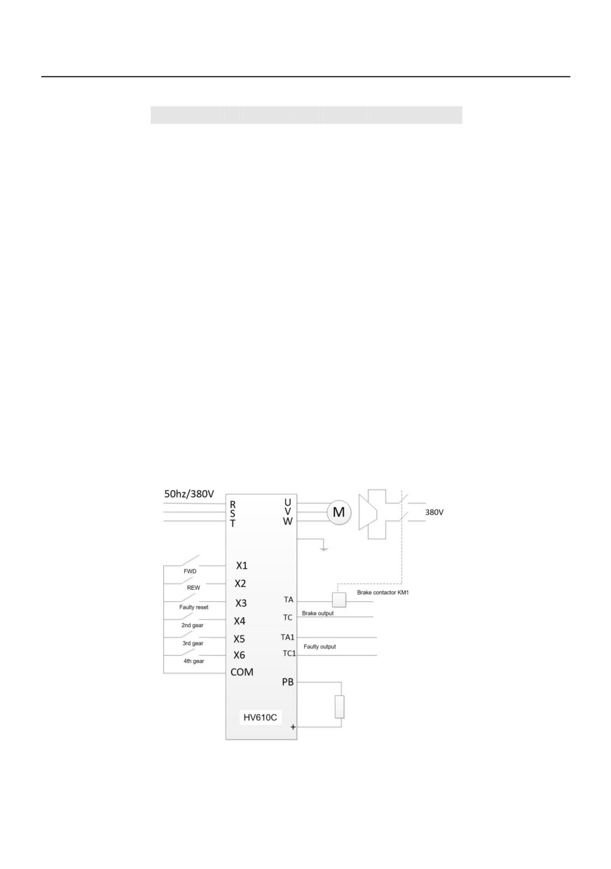
The HV610C is specially designed according to the operation characteristics and operating
conditions of the crane. It is widely used in gantry crane industry, including lifting and transitional
movement mechanism. As shown in the figure below:
2. Examples of the typical wiring of HV610C in Crane applications
The terminal is command channel, multi-segment speed.
frequency reference, two-wire connection mode, brake output control, fault output.
Note: Built-in braking unit of 22KW and below, external braking unit is required for more than
22KW (built-in braking unit is optional). Braking resistors are selected according to customer
requirements. See the resistor selection guide for details.
155
3. Introduction to lifting sequence
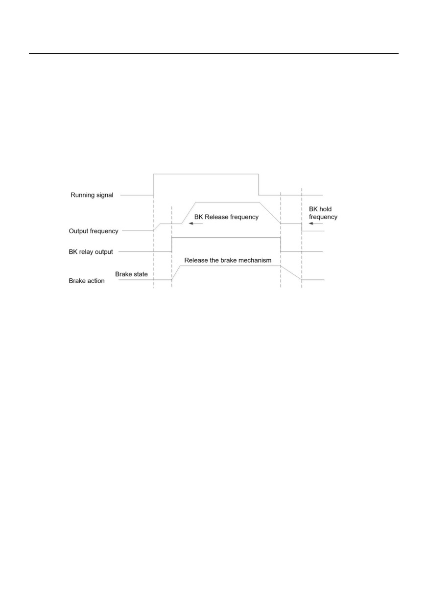
When the brake mechanism of the brake is not energized, it is in the state of holding the brake,
and must be released under the condition that the brake mechanism is energized; because the action
of the brake requires mechanical action, therefore there is a mechanical delay between the drive's
brake output signal and the brake status, and the release time and the brake time must be set
according to the mechanical delay of the actual brake. In theory, the setting of these two parameters is
actually slightly longer than the mechanical delay to avoid the phenomenon of slip hooks.
4. Motor parameters self-tuning
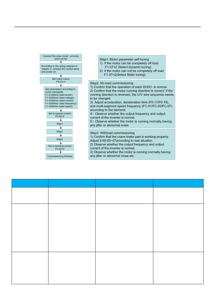
HV610C has the function of motor parameters self-turning . It should be noted that, when
controlling the tapered motor, both dynamic and static setting functions can open the brake of the
tapered motor.Therefore, during the tapered motor parameter setting time, parameter
setting operation only can start when the crane does not carry a heavy load or the safety have ensured.
156
5. Debugging steps
Before the initial application, please debug the frequency converter according to the requirements
of following processes.
6. Special function code of braking timing
Function code
Name
Setting parameter
Description
Factory default:2.00hz
Output frequency before the
A9-00
Run up release frequency
Range:0~20.00hz
brake is fully opened.
During the time from the start
opening to the full opening of
Factory default:0.4s
the mechanical brake, the
A9-01
Run up release time
Range:0~20.0s
inverter keep the frequency
output of A9-00.
After the running command is
Factory default:3.00hz
canceled, when the output
A9-02
Run up hold frequency
Range:0~20.00hz
frequency during the stop is
lower than the set value, the
157

inverter immediately outputs
the command to close the
brake.
This time is from start brake
Factory default:0.3s
to full brake, During this
A9-03
Run up hold time
Range:0~20.0s
period, the inverter keep the
frequency output of A9-02
Run
down
release
Factory default:0.6hz
Output frequency before the
A9-04
frequency
Range:0~20.00hz
brake is fully opened.
During the time from the start
opening to the full opening of
the mechanical brake, the
Factory default:0.2s
A9-05
Run down release time
inverter keep the frequency
Range:0~20.0s
output of A9-04.
After the running command is
canceled, when the output
frequency during the stop is
Factory default:3.00hz
lower than the set value, the
A9-06
Run down hold frequency
Range:0~20.00hz
inverter immediately outputs
the command to close the
brake.
This time is from start brake
Factory default:0.5s
to full brake, During this
A9-07
Run down hold time
Range:0~20.0s
period, the inverter keep the
frequency output of A9-06.
0:Invalid
A9-29
Elevator enable
1:Valid
03:Braking for translation
F5-02
Relay function
46:Braking for lifting
158
7. Use of application Macros
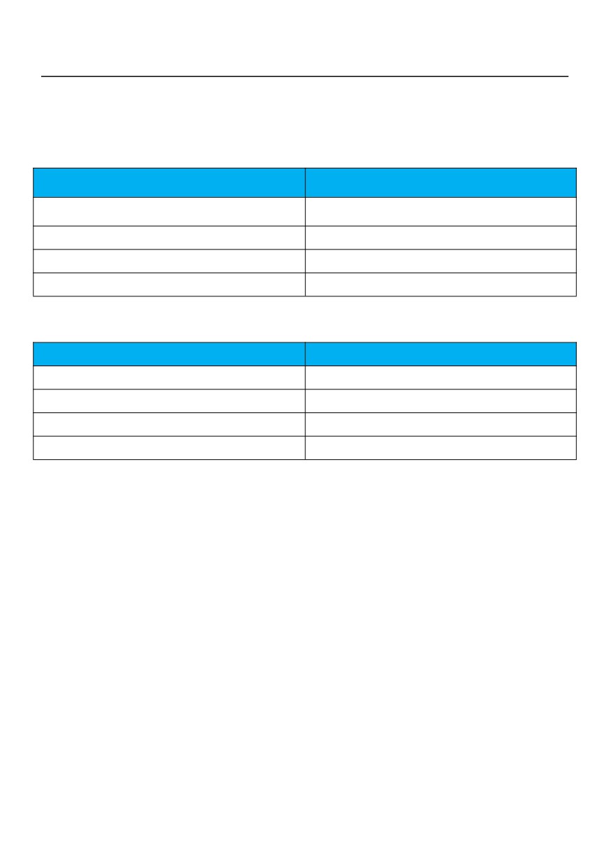
Set FP-01= 1111 is for lift movement application macros,in this way, the parameters are modified as
follow:
Function code
Modified value
F0-01(control mode)
0(vector control)
F0-17(acceleration tim)
2.0s
F0-18(deceleration time)
1.5s
F4-02(relay function)
46(lifting brake dedicated)
Set FP-01= 2222 is for translation movement application macros,in this way, the parameters are
modified as follow:
Function code
Modified value
F0-01(control mode)
2(VF control)
F0-17(acceleration time)
12.0s
F0-18(deceleration time)
5.0s
F4-02(relay function)
03(translation brake dedicated)
159
Product Feedback
Dear users:
Thank you for your interest and purchasing of HNC products!
HNC adheres to the "user-centric", based on customer demand, and offering full customer service to
enhance customer satisfaction.
We hope to learn about your present and future demand for HNC products as well as your valuable
feedback of the products. In order to help you get our service faster and more convenient, please visit our
1) Download the product manual you need.
2) Read and download all kinds of product technical information, such as operation instruction, product
specification, features, FAQ, etc.
3) Application cases.
4) Technical consultation, on-line feedback
5) Feedback product information and customer requirement information by e-mail.
6) Inquiry for the latest products, obtain various types of warranty and extend additional service, etc.
160
Warranty
Agreement
1. The warranty period of the product is 18 months (refer to the barcode on the equipment).
During the warranty period, if the product fails or is damaged under the condition of normal use by
following the instructions, HNC Electric will be responsible for free maintenance.
2. Within the warranty period, maintenance will be charged for the damages caused by the
following reasons:
a. Improper use or repair/modification without prior permission
b. Fire, flood, abnormal voltage, other disasters and secondary disaster
c. Hardware damage caused by dropping or transportation after procurement
d. Improper operation
e. Trouble out of the equipment (for example, external device)
3. If there is any failure or damage to the product, please correctly fill out the Product
Warranty Card in detail.
4. The maintenance fee is charged according to the latest Maintenance Price List of HNC
Electric.
5. The Product Warranty Card is not re-issued. Please keep the card and present it to the
maintenance personnel when asking for maintenance.
6. If there is any problem during the service, contact HNC Electric’s agent or HNC Electric
directly.
7. This agreement shall be interpreted by HNC Electric Limited.
161