HV610C Series Frequency Inverter. User Manual (Version: 3.1.14) - page 2

Section II.
Installation &Wiring
Output voltage range :
0V to 10V Output current
range: 0mA to 20mA.
Optical coupling isolation, bipolar open collector output
voltage range: 0V ~ 24V output current range: 0mA ~
20mA
Note: CME of digital output location is internally isolated
DO-CME
Digital output 1
from com of digital input location, but at the factory it is
shorted to COM via short connector
2CME on the
Digital
control board (DO1 is driven by + 24v by default at this
Output
time). When DO1 is driven by an external power supply,
the short connector 2 must be unplugged.
Constrained by function code F5-
00" FM terminal
High
speed
output mode selection" as high-speed pulse output, the
FM- COM
pulse output
highest frequency is 100 kHz; When it is exported as
open collector, it is the same as DO1 specification.
TA-TB
Normally closed
Contact driving capacity:
Relay
AC250V, 3A, COSθ=0.4
output1
TA-TC
Normally open
DC30V, 1A
15
Section II. Installation &Wiring
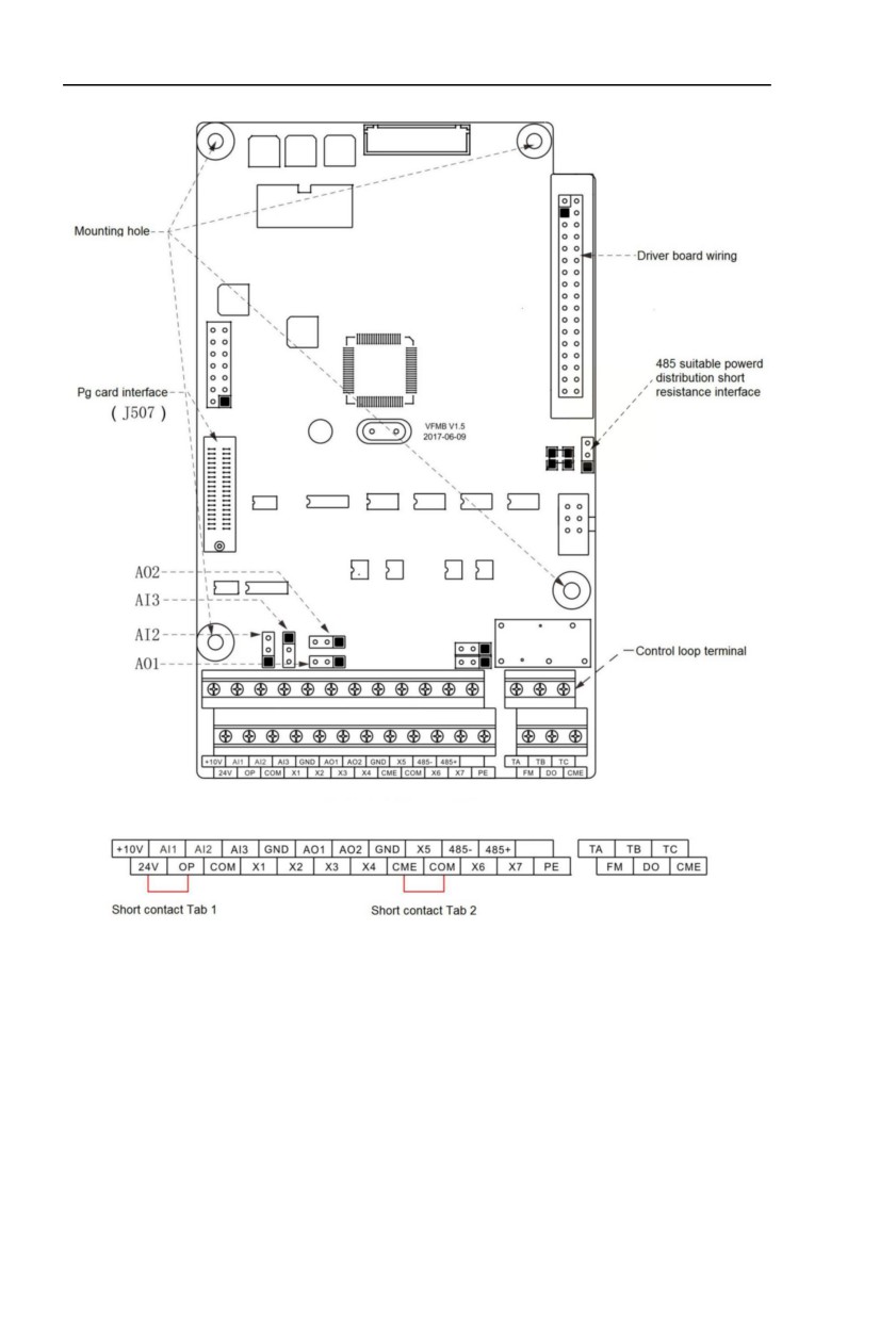
Control board terminal layout
16
Section II. Installation &Wiring
2.5.2 Description of wiring of control terminals
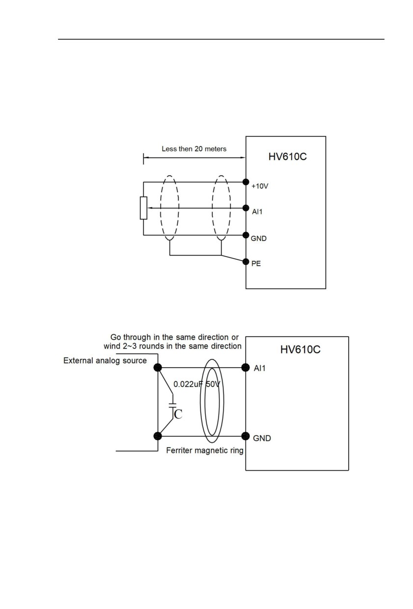
1) Analog input terminal
Because the weak analog signal will be easily affected by the external interference,
generally shielded cable shall be used, the cable length shall be as short as possible and no
longer than 20 meters, as shown in Fig. 2-5.1. In case the analog signal is subject to severe
interference, analog signal source side shall be installed with filter capacitor or ferrite magnetic
ring, as shown in Fig.2-5.2.
Fig. 2-5.1 Analog input terminal wiring diagram
Fig.2.5.2 Analog input terminal processing wiring diagram
17
Section II. Installation &Wiring
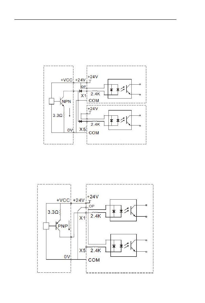
2) Digital input terminal
It needs to employ shielded cable generally, with wiring distance of no longer than 20
meters. When valid driving is adopted, necessary filtering measures shall be taken to prevent
the interference to the power supply.
It is recommended to use the contact control mode.
a) X terminal wiring method (The drain wiring mode)
Fig.2-5.3 Drain wiring mode
This is one of the most commonly used connection mode. If you use an external power
supply, J9 jumper must be removed, and connect the external positive power supply to SP,while
negative power supply to X port.
b)X terminal wiring method (The source wiring mode)
Fig. 2-5.4 Source wiring mode
18
Section II. Installation &Wiring
This connection mode must make SP of jumper J9 connect to COM port,and connect +24V
and public terminal of external controller together.If you use an external power supply,jumper J9
must be removed,and connect external negative power supply to SP ,while positive power
supply to X port.
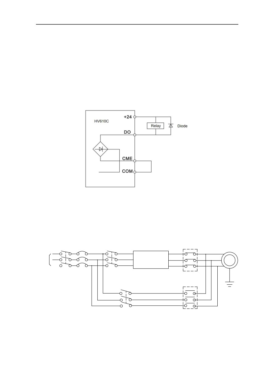
3) Digital output terminal
When drive relay is essential for digital output terminal,you should add absorption diode to
both sides of relay coil.Or +24V dc power supply will be easily damaged.
Caution : The polarity of the absorption diode must be installed correctly according to the
picture below.Or +24V dc power supply will immediately get burnt after digital output terminal
outputs.
Fig. 2-5.5 Digital output terminal wiring diagram
2.6 Standby circuit
Inverter fault or jump may cause great breakdown loss or other accident. To avoid this
happens, please add the standby circuit below to ensure security.
Note:Confirm and test the running characteristic of the standby circuit, make sure that the
industrial phase and the converter phase are in the same direction.
MCC1
R
R
U
S
S
V
M
T
T
Inverter
W
3~
3-phase AC power supply
Interlock AC contactor
MCC2
Fig. 2-6.1
19
Section IV. Keyboard Operation
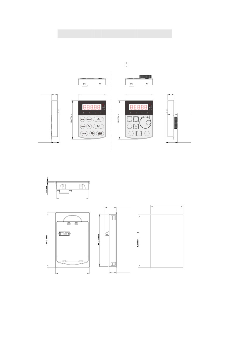
4.1 Keyboard size
4.1.1 HV610C keyboard specification
D=16mm
W=72mm
W=72mm
D=16mm
D1=25.5mm
E NT ER
PRG QUICK
ENTER
RU N
J OG
S TO P
K
RE SE T
D2=20.5mm
D2=29.6mm
Fig. 4-1.1
4.1.2 Keyboard warehouse dimension
77mm
D1=28.3mm
W=81mm
D1=18mm
Fig. 4-1.2
20
Section IV. Keyboard Operation
4.2 Display Interface
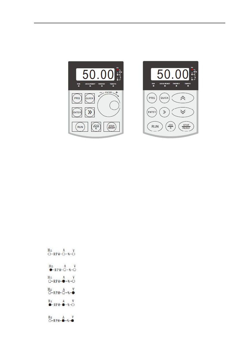
Modification of function parameter, monitoring of inverter operation, control of inverter
operation (start and stop) can be performed through the operation panel.Its shape and function
area are shown as below:
Fig. 4-2.1
4.2.1 Indicator light indicates run
RUN: When the light is on, it indicates that the frequency inverter is in operation, and when
the light is off, it indicates that the frequency inverter is in shutdown state
LOCAL/REMOT: Keyboard operation, terminal operation and remote operation
(communication control) indicator light
FWD/REV: Positive and negative rotation indicator light, which indicates that it is in reverse
rotation when the light is on
TUNE/TC: Tuning / torque control / fault indicator light, light on indicates torque control
mode, light slow flashing indicates tuning state, and light flash indicates fault
state.
The unit indicator lamp is used to indicate the unit of the current
display data (○ marks off, ● marks on). There are the following units:
Hz frequency unit
A current unit
V voltage unit
RMP rotational speed unit
% percentage
21
Section IV. Keyboard Operation
4.3 Examples for parameter setting
4.3.1 Methods of checking and modifying function codes
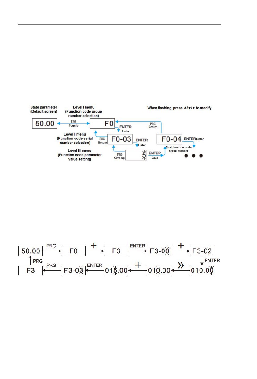
The operation panel of this series of frequency inverters uses a three-level menu structure
to set parameters and other operations.
The three-level menus are: function parameter group (I - level menu) → function code (II -
level menu) → function code setting value (level III menu).
Description: press PRG key or enter key to return to the level II menu when operating the
level II menu. The difference between the two is: press enter to save the setting parameters and
return to the secondary menu, and automatically transfer to the next function code; while
pressing PRG key is to abandon the current parameter modification and directly return to the
secondary menu of the current function code serial number.
Example: example of setting function code F3 - 02 to 15.00 Hz from 10.00 Hz
In the level III menu state, if the parameter does not flash, it indicates that the function code
cannot be modified. Possible reasons are:
This function code is an unmodified parameter, such as frequency inverter type, actual
detection parameter, operation record parameter, etc.
This function code cannot be modified in the running state. It can only be modified after
shutdown.
22
Section IV. Keyboard Operation
4.3.2 Two quick search modes for function code parameters there
Are many function codes in this series. In order to facilitate quick search by users, the
frequency inverter also provides two quick search methods for function codes:
1) Selecting and customizing common function codes and users, up to 30 of which can be
customized, to form a user-defined code function code set; the user determines the function
parameters to be displayed through the FE group
2) Automatically arranges the function codes different from the factory values and the
frequency inverters for quick selection by the user;
This provides three function code lookup methods, the display code of each parameter
display method is:
Parameter display mode
Display
Function parameter mode
--F--
User - customized parameter method
--U-
The method for changing parameters by the users
--C-
The display modes of the three function codes are switched by the quick key on the panel
( FP.03 is set to 11 ), and the search or modification method after entering the function codes of
each group is the same as that of the previous keyboard operation:
4.3.3 Commissioning
The series of frequency inverters has three operation control modes, which including
keyboard control, terminal control and RS-485 control. Its control can be selected by setting the
function code F0-02.
Through keyboard operation, the function code F0-02=0, i.e. the panel start-stop control
mode, presses the run key on the keyboard, and the frequency inverter starts to run ( the run
indicator lights up ); When the frequency inverter is running, press the stop key on the keyboard
to stop the frequency inverter ( the run indicator goes out )
4.3.4 Motor characteristic parameter setting and self - learning
When the frequency inverter operates in the “vector control" (F0-01 = 0 or 1) mode, it is
highly dependent on accurate motor parameters. This is one of the important differences from
the “VF control" (F0-01=2) mode. In order for the frequency inverter to have good driving
performance and operating efficiency, the frequency inverter must obtain the preparation
parameters of the controlled motor.
23

Section IV. Keyboard Operation
Motor 1
Parameter description
Description
parameter
Rated power / voltage / current / frequency / speed of
Model parameters,
F1-01 F1-05
motor
manual input
Equivalent stator resistance, inductance, rotor
F1-06 F1-20
Tuning parameter
inductance, etc. inside the motor
Methods for obtaining the internal electrical parameters of the controlled motor by the
frequency inverter
include dynamic identification, static identification, manual
input of motor
parameters, etc.
Identification
Identification
Application
method
effect
No-load
Suitable for asynchronous motors. Occasions where the
dynamic
Best
motor and the application system are conveniently separated
identification
On-load
Suitable for asynchronous motors. Where the motor is not
May
dynamic
easily separated from the application system
identification
It is only suitable for asynchronous motors, where it is
Static
difficult to separate the motor from the load and dynamic
Poor
identification
identification of operation is not allowed
It is only suitable for asynchronous motors. When the motor
is difficult to separate from the application system, the
Manually enter
parameters of the same type of electric machine
May
parameters
successfully identified by the frequency inverter are copied
and input into the corresponding function codes of F1-00 ~
F1-10
Automatic tuning of motor parameters (motor self - learning) steps are as follows:
The following explains the parameter identification method of the default motor 1 as an
example. The identification method of the motor 2 is the same as that of the default motor 1,
except that the function code number needs to be changed in a targeted way:
z
If the motor can be completely disconnected from the load, under the condition of
power failure, the motor can be mechanically separated from the load so that the
motor can rotate freely without load.
z
After power on, first select the frequency inverter command source (F0 - 02) as the
operation panel command channel.
z
Accurately input the nameplate parameters of the motor (for example, F1-00 ~F1-
24

Section IV. Keyboard Operation
05). Please input the parameters of the lower surface according to the actual
parameters of the motor (according to the current motor selection)
z
If it is an asynchronous motor, then F1-37 (tuning selection, for motor 2, it should
be FB-37 function code) please select 2 (asynchronous motor fully tuned), press
enter to confirm, at this point, the keyboard shows STUDY, as shown in the
following figure:
Then press the run key on the panel, the frequency inverter will drive the motor to
accelerate and decelerate, rotate forward and backward, the operation indicator light will
illuminate, and the operation duration will be recognized for about 2 minutes. When the above
display information disappears, the normal parameter display state will be returned, indicating
that the tuning is completed. After the complete tuning, the frequency inverter will automatically
calculate the following parameters of the motor:
F1 - 06: Asynchronous motor stator resistance
F1 - 07: Asynchronous motor rotor resistance
F1 - 08: Induction motor leakage inductance
F1 - 09: Induction motor mutual inductance resistance
F1 - 10: Asynchronous motor no-load current
If the motor cannot be completely disconnected from the load, F1- 29 (motor 2 is FB - 29)
please select 1 (asynchronous motor is still tuned), and then press the run key on the panel to
start the motor parameter identification operation.
25

Section IV. Keyboard Operation
4.3.5 Motor parameter automatic tuning
Vector control running mode:before running, user must accurately input motor nameplate
parameters. HV610C series inverter will be matching standard motor parameter according to
this nameplate. Vector control methods are very much dependent on motor parameters, to get
good control performance, accurate control motor parameters must be acquired.
Motor parameter auto tuning procedure is as follows:
Firstly, select command source(F0.02) as operation panel command channel.Secondly,
input parameters below in accordance with motor actual parameter:
Motor selection
Parameter
F1.00:Motor type selection
F1.01:Motor rated power
Motor 1
F1.02:Motor rated voltage
F1.03:Motor rated current
F1.04:Motor rated frequency
F1.05:Motor rated revolving speed
A2.00:Motor type selection
A2.01:Motor rated power
Motor 2
A2.02:Motor rated voltage
A2.03:Motor rated current
A2.04:Motor rated frequency
A2.05:Motor rated revolving speed
Table 4-3.4
E.g:Asynchronous motor parameter tuning
If motor and the load can be totally separated, please select F1.37 (Motor 2as A2.37) to 2
(Asynchronous machine complete tuning), then press RUN key on keyboard panel, inverter will
automatically calculate the motor of the following parameters:
Motor selection
Parameter
F1.06:Asynchronous motor stator resistance
F1.07: Asynchronous motor rotor resistance
Motor 1
F1.08: Asynchronous motor leakage inductance
F1.09: Asynchronous motor mutual inductance
F1.10: Asynchronous motor no-load current
A2.06: Asynchronous motor stator resistance
A2.07: Asynchronous motor rotor resistance
Motor 2
A2.08: Asynchronous motor leakage inductance
A2.09: Asynchronous motor mutual inductance
F2.10: Asynchronous motor no-load current
Table4-3.5
If motor and the load can not be totally separated, please select F1.37(Motor 2\3\4 as
A2\A3\A4.37) to 1(Asynchronous machine static tuning), then press RUN key on keyboard panel.
26

Section IV. Keyboard Operation
4.4 Test running
HV610C General machine type factory setting value
Code
Factory setting
Description
F0.01
0
Speed sensorless vector control(SVC)
F0.02
0
Operation panel command channel(LED OFF)
F0.03
4
AI3 (Potentiometer)
Users set motor parameters F1.00~F1.05 to correct values, after parameters auto tuning,
motor operation can be directly controlled through keyboard, while frequency can be set through
keyboard potentiometer.
27
Section V. Parameter Function Table
Caution:
The symbols in the function table are explained as follows:
“★” : indicates that the parameter setup value cannot be modified when the inverter is in the
running status.
“●”:indicates that the parameter value is the actual detection record and cannot be modified.
“Change limit” indicates if the parameter is adjustable during operation.
When FP.00 is set to non-zero value, it means that the parameter protection password is
set and only when correct password is input can the user enter the parameter menu. To cancel
the password, FP.00 should be set to 0.
In the user set parameter mode , parameter menu is not protected by password protection.
F group, A group are of basic function parameters, U group is the monitor function group.
5.1 Monitor function group:U0.00-U0.61
U0 parameter group is used to monitor inverter running status .Customers can check through
panel for field commissioning as well as read parameter value through communication for position
machine monitoring. Among which, U0.00~U0.31 is defined for running or stop monitor parameter
by F7.03 , F7.04, F7.05.
For specific parameter function code、parameter name and minimum unit, please refer to the
table below.
Function code
Designation
Unit
U0.00
Running frequency(Hz)
0.01Hz
Inverter current actual setting frequency
U0.01
Setting frequency(Hz)
0.01Hz
Inverter current actual output frequency
U0.02
DC bus voltage(V)
0.1V
Detection value of DC bus voltage
U0.03
The output voltage(V)
1V
Inverter actual output voltage
U0.04
Motor output current(A)
0.01A
Valid value of motor actual current
U0.05
The output power(kW)
0.1kW
The calculated value of actual output power of motor
U0.06
Output torque(%)
0.1%
The output torque of the motor
28
Section V. Parameter Function Table
U0.07
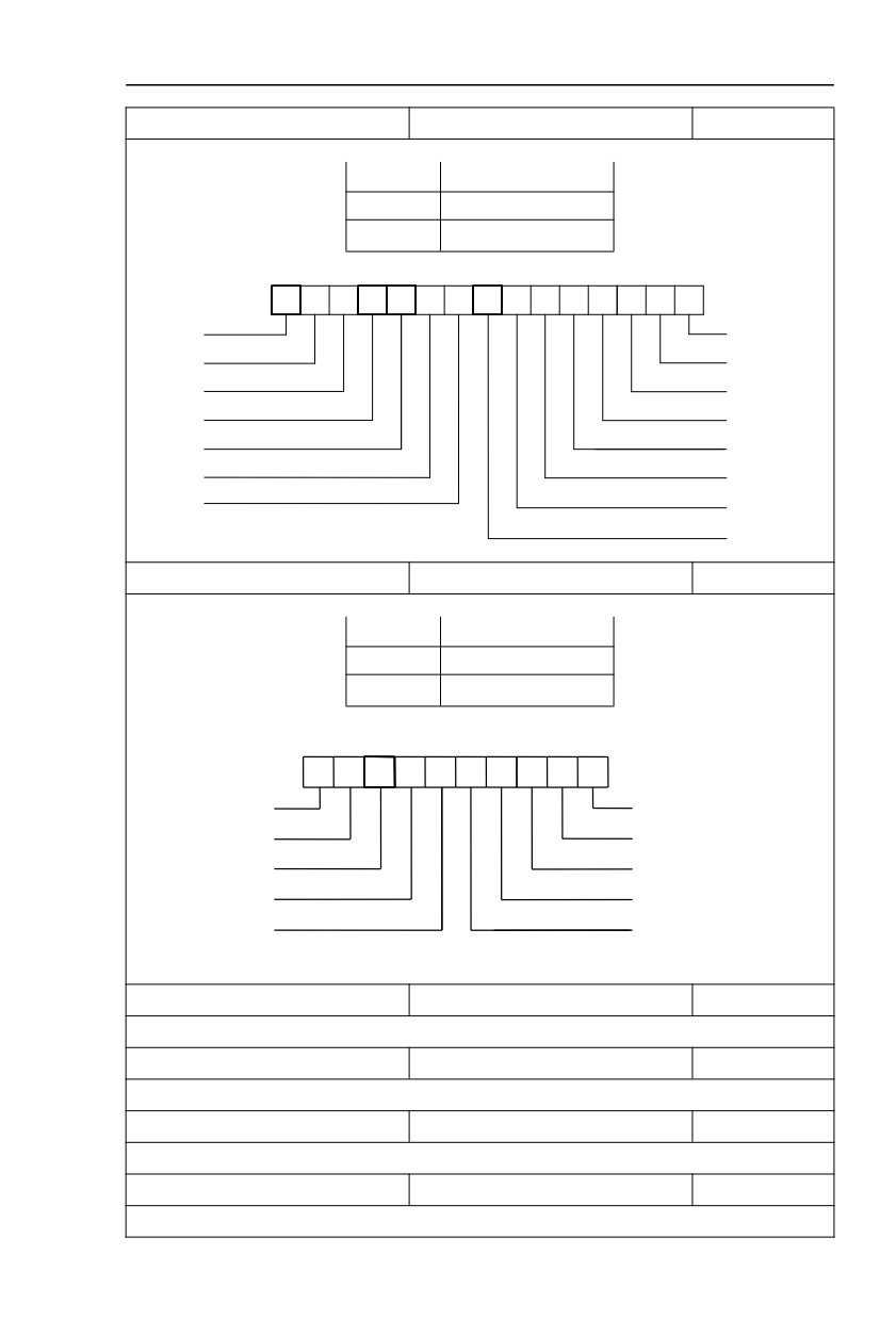
DI input status
1
IO input status,it’s value is a hexadecimal digit.Each bit corresponds to each input terminal state:
0~14 bit
Input status
0
Invalid
1
Valid
14
13
12
10
9
8
7
6
5
4
3
2
1
0
2
2
2
211
2
2
2
2
2
2
2
2
2
2
2
14
13
12
11
10
9
8
7
6
5
4
3
2
1
0
VDI5
DI1
VDI4
DI2
VDI3
DI3
VDI2
DI4
VDI1
DI5
DI10
DI6
DI9
DI7
DI8
U0.08
Y output status
1
IO output status,it’s value is a hexadecimal digit.Each bit corresponds to each output terminal state
:
0~9 bit
Output status
0
Invalid
1
Valid
9
7
6
5
4
3
2
1
0
2
28
2
2
2
2
2
2
2
2
9
8
7
6
5
4
3
2
1
0
VDO5
FMR
VDO4
TA-TB-TC
VDO3
TA2-TB2-TC2
VDO2
DO
VDO
DO2
U0.09
AI1 voltage(V)
0.01V
AI1 input voltage, corrected by AC.00~AC.03
U0.10
AI2 voltage(V)
0.01V
AI2 input voltage, corrected by AC.04~AC.07
U0.11
AI3 voltage(V)
0.01V
AI3 input voltage, corrected by AC.08~AC.11
U0.12
Count value
1
Fb function group count function Fb.08~Fb.09
29
Section V. Parameter Function Table
U0.13
Length value
1
Fb function group fixed length function Fb.05~Fb.07
U0.14
Load speed display
1
Motor actual running speed
U0.15
PID set point
1
PID percentage of reference value for running adjustment.
U0.16
PID feedback
1
PID percentage of feedback value for running adjustment.
U0.17
PLC stage
1
PLC program running stage-display
U0.18
PULSE pulse input frequency(kHz)
0.01kHz
Display PULSE pulse input frequency,unit 0.01Khz
U0.19
Speed feedback(Unit 0.1Hz)
0.1Hz
synchronous speed,accurate to 0.1hz
U0.20
Surplus running time
0.1Min
Display surplus running time, used for regular operation control.
U0.21
AI1 voltage before correction
0.001V
AI1 voltage before correction ,used for AC function group parameter AC.00~AC.03 to correct AI1 voltage
U0.22
AI2 voltage before correction
0.001V
AI2 voltage before correction ,used for AC function group parameter AC.04~AC.07 to correct AI2 voltage
U0.23
AI3 voltage before correction
0.001V
AI3 voltage before correction ,used for AC function group parameter AC.08~AC.11 to correct AI3 voltage
U0.24
Linear velocity
1m/Min
Linear velocity is calculated according to angular velocity and diameter, used for constant tension control
and constant linear velocity control.
U0.25
Current power on time
1Min
The cumulative power on time of the inverter.
U0.26
Current running time
0.1Min
The cumulative running time of the inverter.
U0.27
PULSE pulse input frequency
1Hz
Display PULSE pulse input frequency ,unit 1Hz.
U0.28
Communication set value
0.01%
Communication set value
U0.29
Encoder feedback speed
0.01Hz
PG feedback speed, accurate to 0.1hz
30
Section V. Parameter Function Table
U0.30
Main frequency X display
0.01Hz
F0.03 main frequency source set frequency
U0.31
Auxiliary frequency Y display
0.01Hz
F0.04 auxiliary frequency source set frequency
U0.32
View arbitrary memory address value
1
To view arbitrary memory address, advanced commissioning function.
U0.33
Reserve
0.0°
U0.34
Motor temperature
1℃
Display motor temperature. Other device temperature can also be tested through different
temperature
measuring point.
U0.35
Target torque(%)
0.1%
Target torque setup.In torque control mode, it is used to check the set target torque.
U0.36
Rotary variable position
1
It’s rotor position when speed feedback.
U0.37
Power factor angle
0.1
Current power factor angle,power factor=COS(angle),angle=0,maximum power.
U0.38
ABZ position
0.0
ABZ incremental feedback position information of encoder calculation.
U0.39
VF target voltage separation
1V
VF target voltage when power supply separating.
U0.40
VF output voltage separation
1V
VF output voltage when power supply separating.
U0.41
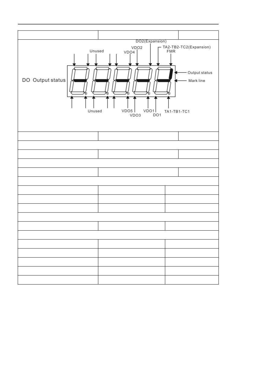
DI input status intuitive display
-
Display DI input status intuitively, offer DI input information more detailed than U0.07, advanced
display function.
31
Section V. Parameter Function Table
U0.42
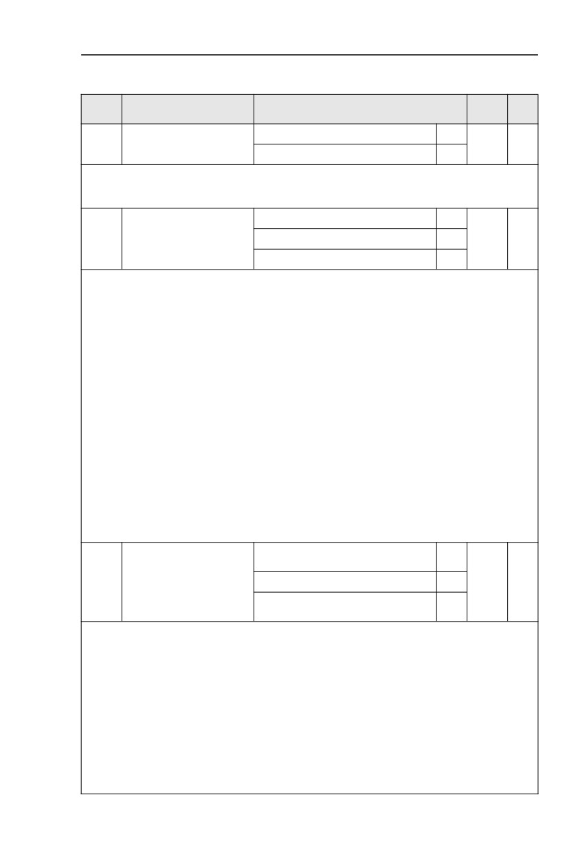
DO output status intuitive display
-
Display DO output status intuitively, offer DO output information more detailed than U0.08, advanced
display function.
U0.43
DI function status intuitive display1
1
Display DI function status 1 intuitively ,display(function 01-40)
U0.44
DI function status intuitive display2
1
Display DI function status 2 intuitively ,display (function 41-80)
U0.45
Fault information
0
Fault information query.
U0.46-U0-57
Reserved
-
U0.58
Z-pulse counter
1
U0.59
Setting frequency(%)
0.01%
-100.00%~100.00%
U0.60
Running frequency(%)
0.01%
-100.00%~100.00%
U0.61
Inverter status
1
U0.62
Current fault code
1
U0.63
Point to point communication
0.01%
U0.64
From the number of stations
1
U0.64
Torque limit
0.01%
32
Section V. Parameter Function Table
5.2 Basic function group:F0.00-F0.28
FactoryChange
Code
Description/Display
Setting Range
Setting
Limit
G type(constant torque load type)
1
F0.00
GP type display
-
●
P type(draught fan,pump load type)
2
This parameter is only for the use of viewing the factory model. It is can not be modified.
1:It is applicable to the constant torque load of specified rated parameter
2:It is applicable to the variable torque load of specified rated parameter(draught fan,pump load type)
Speed sensorless vector control(SVC)
0
F0.01
Motor 1 control mode
Speed sensor vector control(FVC)
1
0
★
V/F control
2
0:Speed sensorless vector control
It refers to the open-loop vector control that is generally applied to high performance control field. One
inverter can only drive one motor. E.g:machine tool, centrifugal machine, fiber drawing machine, injection
molding machine’ load etc.
1:Speed sensor vector control
It refers to the closed-loop vector control and encoder must be added to the motor end.Inverter must
be matching with the same type PG card of the encoder. This control mode is suitable for high precision
speed control and torque control field. One inverter can only drive one motor. E.g : high speed
papermaking machinery , hoisting machinery , elevator’ load etc.
2:V/F control
V/F control mode is suitable for fields that load demand is not high or one inverter can drive multiple
motos. E.g:draught fan, pump’ load etc.
Tips:Motor parameters must be identified before choosing vector control mode.Only accurate motor
parameters can play the advantage of vector control mode. Users can get better performance by adjusting
speed regulator group F2 parameters(motor 2 for group A2)
FVC is generally used for permanent magnet synchronous motor, while part of the small power
applications can select V/F control mode. HV610C series support specific models of permanent magnet
synchronous motor sensorless vector control mode. Please refer to HV610C users manual and HV610CS
dedicated users manual for using method.
Operation panel command channel(LED
0
off)
F0.02
Command source selection
Terminal command channel(LED on)
1
0
☆
Serial port communication command
2
channel(LED flashing)
Inverter control commands include : run, stop, forward rotation (FWD), reverse rotation (REV),
forward jog (FJOG), reverse jog (RJOG), etc.
0: Operation panel command channel (“LOCAL/REMOT” LED off);
Perform running command control with RUN, MF.K and STOP/RESET keyson the operation panel.
1: Terminal command channel (“LOCAL/REMOT” LED on);
Perform running command control with multifunctional input terminals such as FWD, REV, FJOG,
RJOG, and so on.
2:Serial port communication command channel (“LOCAL/REMOT” LED flashing).
The running command is given by the host computer via the communication mode. When the item is
choosen,it must be equipped with communication card( Modbus RTU 、 Profibus DP card 、 users
programmable control card or CANopen card and so on).
For the communication protocol, please refer to
“FD group communication parameters”and
33
Section V. Parameter Function Table
supplementary explanation of corresponding communication card for details.
Supplementary explanation for communication card is allotted with communication card.This manual
contains a brief description of communication card.
Digital setup(Preset frequency F0.08,
UP/DOWN can be modified, power off
0
without memory)
Digital setup(Preset frequency F0.08,
UP/DOWN can be modified, power off
1
with memory)
AI1
2
Main frequency source X
AI2
3
F0.03
4
★
selection
AI3
4
Pulse setup(X5)
5
MS command
6
Simple PLC
7
PID setup
8
Communicaton setup
9
This parameter is used to select the main reference frequency input channel. Totally 10 main reference
frequency channels:
0:Digital setup(power off without memory)
Initial value of set frequency equals to F0.08
“preset frequency”.User can change inverter set
frequency value through keyboard ∧ key and ∨ key ( or multi-function input terminal UP,DOWN).
Inverter power on after powered off, frequency set value restored to F0.08 “Preset frequency”.
1:Digital setup(power off with memory)
Initial value of set frequency equals to F0.08
“preset frequency”. User can change inverter set
frequency value through keyboard ∧ key and ∨ key ( or multi-function input terminal UP,DOWN).
Inverter power on after powered off, frequency set value restored to the value that equals to setupof
last power off time. Correction is memorized through keyboard ∧ key and ∨ key or terminal UP,DOWN.
What needs to be reminded is, F0.23 is “Digitalsetupfrequencymemoryselection”. F0.23 is used to
select correction whether to be memorized or cleared and is relevant to stop, irrelevant to power off
memory, please pay attention during operation.
2:AI1
3:AI2
4:AI3
The frequency is determined by the input terminal of the analog quantity. The HV610C control board
provides 3 analog input terminals (AI1, AI2, AI3). Among them, AI1 is 0V ~ 10V voltage input, AI2 can be
0V ~ 10V voltage input, or 4mA ~ 20mA current input, which is selected by the J8 jumper on the control
board, AI3 is -10V ~ 10V voltage input. 1. The input voltage value of AI2, AI3 and the corresponding
relationship with the target frequency can be freely selected by the user.
This series of inverters provide 5 sets of corresponding relationship curves, of which 3 sets of curves
are linear relationships (2-point corresponding relationships), and the user can set them through the F4
group function code. The 2 sets of curves are arbitrary curves with 4 points corresponding to the
relationship (factory parameters). The function code F4-33 is used to set the AI1~AI3 three-way analog
input, respectively select which one of the 5 groups of curves.
5:Pulse setup(X5)
Pulse setup is set through terminal pulse. Signal standard : voltage range 9V~30V, frequency range
0kHz~100kHz. Set pulse can be only input through multi-function input terminal X5.
34
Section V. Parameter Function Table
Relationship between X5 input pulse frequency and corresponding settings is set through F4.28~F4.31. It
is linear relationship(2-point correspondence). Pulse input 100.0% refers to the percentage of F0.10 .
6:MS command
MS command running mode is set through different combination mode of digital input DI terminal.
There are 4 MS command terminals with 16 status of HV610C series. FC group function codes correspond
to 16 “MS command”. “MS command” is percentage relativing to F0.10 ( maximum frequency).
When digital input terminal DI is used as MS command terminal, user should set through F4 group.For
specifications please refer to F4 group.
7:Simple PLC
When frequency source is set to 7, running frequency source can be switched to any frequency
command during 1~16.
User can set frequency command retention time and acceleration/deceleration time respectively.For
specifications please refer to FC group .
8:PID
Running frequency is the output of PID control process. Generally used for field process closed-loop
control.
When PID is chosen, user should set relevant parameters of FA group “PID function”.
9:Communication setup
Means that the main frequency source is given by the host computer through communication
Digital setup(preset frequency F0.08,
UP/DOWN adjustable, power off without
0
memory)
Digital setup(preset frequency F0.08,
UP/DOWN adjustable, power off with
1
memory)
AI1
2
Auxiliary frequency source
AI2
3
F0.04
0
★
Y selection
AI3
4
PULSE setup (Dl5)
5
MS command
6
Simple PLC
7
PID setup
8
Communication setup
9
When the auxiliary frequency source is used as independent frequency reference channel
(i.e.
frequency source switching from X to Y), it is used in the same way as the relative specifications of F0.03.
When the auxiliary frequency source is used as overlap reference (i.e. frequency source selection
switching from X plus Y or X to X plus Y), it has special points as follows:
1. When the auxiliary frequency source is digital reference, the preset frequency
(F0.08) is
nonsensical, and it needs to adjust the main reference frequency through the keys “∧”and “∨” of the
keyboard (or UP andDOWN of multifunctional input terminals).
2. When the auxiliary frequency source is analog input reference (AI1 、 AI2 、 AI3) or pulse input
reference, 100% of input setup is relative to the auxiliary frequency source range,and can be set through
F0.05 and F0.06.
3. When the frequency source is pulse input reference, it is similar to the analog value.
Prompt : There is difference between the auxiliary frequency source Y selection and the main
frequency source X setup value. That is to say, F0.03 and F0.04 cannot use the same frequency reference
channel.
35
Section V. Parameter Function Table
Auxiliary frequency source
Relative to maximum frequency
0
F0.05
0
☆
Y range selection
Relative to frequency source X
1
Auxiliary frequency source
F0.06
0%~150%
0
☆
Y range
When the frequency source selection is frequency overlap reference(F0.07 is set to 1 、 3 or 4), it is
used to determine the adjustment range of auxiliary frequency source. F0.05 is used to determine the
relative object within the range. If it is relative to main frequency, that range will vary with the main
frequency X.
1bit
Frequency source selection
Main frequency source X
0
Main /auxiliary operation result (10bit
1
determine operation relationship)
Switching between X & Y
2
Switching between X & option 1
3
Frequency source stacking
Switching between Y & option 1
4
F0.07
00
☆
selection
Relationship betweenmain
10bit
/auxiliaryfrequency source
Main+auxiliary
0
Main-auxiliary
1
MAX(main frequency source X, auxiliary
2
frequency source Y)
MIN(main frequency source X, auxiliary
3
frequency source Y)
This parameter is used to select frequency setup channel, and of realizing frequency setup through
the compound of main frequency X and auxiliary frequency Y.
1bit :Frequency source selection
0:Main frequency source X
Main frequency source X is the target frequency.
1:Main /auxiliary operation result is targe frequency,operation relationship see “10 bit” for details.
2:Switching between main frequency source X and auxiliary frequency source Y
When terminal 18 (frequency switching) is invalid, main frequency X is target frequency. On the
contrary, auxiliary frequency Y is the target frequency.
3:Switching between main frequency X and main /auxiliary operation result
When terminal 18 (frequency switching) is invalid, main frequency X is target frequency. On the
contrary, auxiliary frequency Y is the target frequency.
4:Switching between auxiliary frequency Y and main /auxiliary operation result
When terminal 18 (frequency switching) is invalid, auxiliary frequency Y is the target frequency. On the
contrary, main frequency X is target frequency.
10bit :Relationship between main/auxiliary frequency source
0:Main frequency source + auxiliary frequency source Y
Operation result of main + auxiliary is target frequency. It realizes frequency stacking set function.
1:Main frequency source - auxiliary frequency source Y
Operation result of main - auxiliary is target frequency.
2:MAX(main frequency source X, auxiliary frequency source Y)
Choose bigger absolute value of the two as target frequency
3:MIN(main frequency source X, auxiliary frequency source Y)
36
Section V. Parameter Function Table
Choose smaller absolute value of the two as target frequency.
Besides, when frequency source is main& auxiliary operation,users can set offset frequency through
F0.21.By stacking offset frequency on main& auxiliary operation result,it could flexible cope with all
kinds of needs.
0.00Hz to maximum frequency(It is only valid
F0.08
Preset frequency
50.00Hz
☆
when frequency source is set to “digital setting”)
When set the frequency source to “digital setting” or “terminal UP/DOWN”, the parameter value is the
initial value of the inverter frequency digital setting.
Consistent direction
0
F0.09
Running direction
0
☆
Reverse direction
1
Modification of this parameter can change the rotary direction of the motor without changing any other
parameters, which is equivalent to the role of switching the rotary direction through adjusting any two lines
of the motor (U, V and W).
When needing to change the rotary direction of the motor, users can modify this parameter rather than
adjust the wiring of the motor.
Caution : When the function code is restored to the factory default value, this parameter value is
restored to 0, which should be used prudently in the applications where the motor rotary direction is not
allowed to change.
F0.10
Maximum frequency
50.00Hz~320.00Hz
50.00Hz
★
When analog input, pulse input(X5), MS command etc are used as frequency source, their respective
100% are relatively calibrated through F0.10.
HV610C maximum frequency could reach 3200Hz. Users can set decimal digits of frequency
command through F0.22 to balance the idex of frequency command resolution and frequency input range.
When F0.22 is set to 1,frequency resolution ratio is 0.1Hz, F0.10 setting range is 50.0Hz~3200.0Hz;
When F0.22 is set to 2, frequency resolution ratio is 0.01Hz, F0.10 setting range is 50.00Hz~320.00Hz.
F0.12 setup
0
AI1
1
AI2
2
F0.11
Frequency source upper limit
0
★
AI3
3
PULSE setup
4
Communication setup
5
It defines the source of frequency upper limit. Frequency upper limit comes from digital setup (F0.12)
or analog input channel. When upper limt is set through analog input, 100% of analog input corresponds to
F0.12.
E.g : When winding control field is in the torque control mode, to avoid material break
phenomenon,users can set upper limit frequency through analog value. When running frequency reaches
value of upper limit , inverter maintains operation at the upper limit frequency.
Frequency lower limit(F0.14) to maximum
F0.12
Frequency upper limit
50.00Hz
☆
frequency(F0.10)
F0.13
Frequency upper limit offset
0.00Hz~maximum frequency F0.10
0.00Hz
☆
When upper limit is set through analog value or PULSE setup, F0.13 will be used as analog
valueoffset. The addition of offset frequency and analog setup value of frequency upper limit is used as
the final setup value of frequency upper limit.
37
Section V. Parameter Function Table
F0.14
Frequency lower limit
0.00Hz to frequency upper limit F0.12
0.00Hz
☆
When the running frequency of the inverter is lower than the frequency lower limit, it can select to
run at frequency lower limit or stop the inverter. Refer to F8.14 function code for details.
F0.15
Carrier frequency
0.5kHz~16.0kHz
-
☆
This function is used to adjust the carrier frequency of the inverter. By adjusting the carrier
frequency, the motor noise can be reduced, the resonance of the mechanical system can be avoided, so
that the leakage current to the ground and the interference of the inverter can be reduced.
When the carrier wave frequency is low, the output current higher harmonic component will be
increased, the motor loss will be increased, and the motor temperature rise will also be increased.
When the carrier wave frequency is high, the motor loss is reduced, and the motor temperature
rise is reduced, but the inverter loss and inverter temperature rise will be increased, and thus the
interference will be increased.
The adjustment of carrier frequency will influence the following items on the performance:
Carrier frequency
low→
high
Motor noise
big→
small
Output current waveform
poor→
well
Motor temperature rise
high→
low
Inverter temperature rise
low→
high
Leakage current
small→
large
Radiation interference
small→
big
Different power of inverter is set with different carrier frequency by the factory. Though user could
modify it , attention should be paid:if carrier frequency is set higher than the factory set valule, it will
lead to inverter radiator temperature rise increasing. User should take inverter derating use, or there
will be danger of overheating alarm.
No
0
Carrier frequency adjusting
F0.16
0
☆
with temperature
Yes
1
Carrier frequency adjusting with temperature refers to the detecting of radiator temperature. When
the temperature is high , carrier frequency automatically decreased to reduce the inverter temperature
rise. On the contrary , when the temperature is low, carrier frequency gradually restored to the set
value.This function could help to reduce the chance of inverter overheating alarm.
F0.17
Acceleration time 1
0.00s~65000s
-
☆
F0.18
Deceleration time 1
0.00s~65000s
-
☆
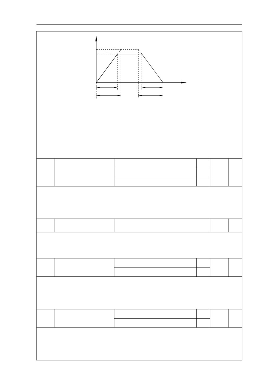
The acceleration time means the time t1 needed for the inverter to accelerate from 0Hz to the
reference frequency(F0.25).
The deceleration time means the time t2 needed for the inverter to decelerate from the reference
frequency (F0.25) to 0Hz.
The descriptionof acceleration and deceleration time are as shown in Fig.5.1:
38
Section V. Parameter Function Table
Output frequency
Hz
Acceleraion/deceleration
reference frequency
Setting frequency
t
Actual acceleration time
Actual deceleration time
t1
t2
Setting acceleration time
Setting deceleration time
Fig.5-1Acceleration/deceleration time schematic diagram
HV610C totally offers 4 groups of speed-up/speed-DOWN time for selection,you can shift through
digital input terminal DI,4 groups of them are shown as follows:
GROUP 1:F0.17、F0.18;
GROUP 2:F8.03、F8.04;
GROUP 3:F8.05、F8.06;
GROUP 4:F8.07、F8.08.
1 second
0
F0.19
Acc./dec. time unit
0.1 seconds
1
1
★
0.01 seconds
2
HV610C offers 3 kinds of speed-up /speed down time unit to meet the need of all kinds of
scene.Respectively for 1 second、0.1 seconds and 0.01 seconds.
Caution:Decimal places as well as corresponding acceleration/deceleration time of the 4 groups may
be changed when modifying this function parameter,special attention should be paid in the process of
application.
Auxiliary frequency source
F0.21
0.00Hz~Maximum frequencyF0.10
0.00Hz
☆
offset frequency
It is valid only at the time of main/auxiliary operation is choosen.
When frequency source is main / auxiliary operation(F0.21
as offset frequency)
,it could make
frequency set more flexible by stacking offset frequency on main& auxiliary operation as the final frequency
set value.
0.1Hz
1
Frequency command
F0.22
2
★
resolution
0.01Hz
2
This parameter is used to dertermine all the function code resolution which is relevant to frequency.
Frequency resolution is 0.1Hz , HV610C maximum output frequency can reach 3200Hz. While
frequency resolution is 0.01Hz, HV610C maximum output frequency is 320.00Hz.
Caution : Parameter (relating to frequency ) decimal digits and corresponding frequency value will
change through modifying F0.22. Special attention should be paid during operation.
Digital setup frequency
Without memory
0
F0.23
0
☆
memory selection upon stop
1
Memory
This function is only valid when frequency source is digital setup.
0: Without memory
Upon power fault or stop of the inverter, set the frequency value back to the setup value of “Preset
Frequency” (F0.08). Frequency modification which set through keyboard “∧” 、 “∨” or terminal UP 、
DOWN is cleared.
39