HNC-180xpT3. Operation Guide (V 2.0 2015.4) - page 3
Program Editing and Management
system prompts you to enter the content to search. Press
, the system highlights the first
block of content that meets the search conditions. You may press F5
to view the
next block of content that meets the search conditions.
5.2.4 Locate a Line
To rapidly locate a line within a program, press F6
, and then press F3
. The system prompts you to enter the line number to locate. Enter the line
number and press
, and the cursor will automatically go to the end of the line within the
program.
5.2.5 Save as
To save an edited or created program as another file, press F6
, and then press
F6
. The system displays the default file name. Press
to save the current
program file with the default name. You may change the file name, and then press
to
save the program with another name. It is recommended to use a file name that has not existed. If
the system fails to save the edited program, a corresponding failure message will be displayed. In
this case, the program is a read-only file and cannot be saved with modification, but you may save
it as another file. If the failure is caused of insufficient storage space, you may delete unnecessary
files and resave the program.
5.2.6 Replace a String of Characters
To replace a string of characters in the program with other characters, press F6
,
and then press F2
. The system prompts you to enter the characters to be replaced.
Press
after entering required information. After that, enter the characters to replace the
66
Program Editing and Management
previous ones, and then press
. The system will automatically replace the string of
characters as required.
5.2.7 Delete a Line
To delete a line within a program, move the cursor to the line, press F6
, and
then press F4
. The system will automatically delete the content of the line.
5.2.8 Edit a Block
To edit a block within a program, press F6
, and then press F5
Based on the cursor position, press F1
or F2
as required, and
then press F3
, F4
or F5
to cut, copy, or paste block
information.
5.3 Create a Program
Press the
key, and then press the F3
key. The system prompts you
to enter a new program name (a random G code name by default). After entering the program
name, you may press
to create a new program by pressing the character keys on the
NCP board.
5.4 Delete a Program
You may delete unnecessary program files when there is no sufficient space with too many
unnecessary files. Do as follows:
1.
Press
, press F1
, and then use the
,
,
, and
keys to select the disk where files required to delete are placed.
67
Program Editing and Management
2.
Select a file from the program list on the right, and use the
,
,
,
and
keys to select the program to be deleted.
3.
Press
, and the system displays the message
4.
Enter Y to delete the program.
5.5 Copy a Program
Follow the instructions below to copy a program:
1.
Press
, press F1
, and then use
,
,
,
and
keys to select the disk where files required to copy are placed.
2.
Select a file from the program list on the right, and use the
,
,
,
and
keys to select the program to be copied.
3.
Press F2
, and select a target directory by using
and
4.
Press F3
to paste the program.
5.6 Verify a Program
Selected programs can be automatically verified and errors will be reported if there is any. New
programs that have not been run on the machine should be verified before auto running. Follow
the instructions below to verify programs:
1. Select a program required to be verified.
2.
Press F6
under
, and press F4
to select a
68
Program Editing and Management
program verification mode.
3.
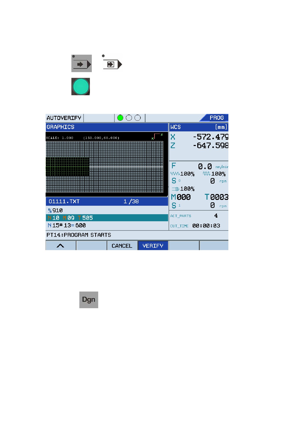
Press
or
to enter the program running mode.
4.
Press
to start verifying the program,
Figure 5.4 Verify programs
If the program is correct, the cursor returns to the head of the program after verification. If the
program is incorrect, the system displays the error message on the screen and the indicator blinks.
You may press
to view related error information.
Note:
y
The machine cannot run during program verification.
y
It is recommended to select difference graphs for verification results to ensure correct
program. For more information, see section 1.3.5 (Figure 1.37).
69

Program Editing and Management
5.7 Restart a Program
If you need to restart a program from the beginning after the program is stopped, press
,
and press F5
. In the Auto or Single Block mode, press
to restart the
program from the beginning.
70
User Operation and Maintenance Information
6 User Operation and Maintenance
Information
6.1 Environmental Requirements
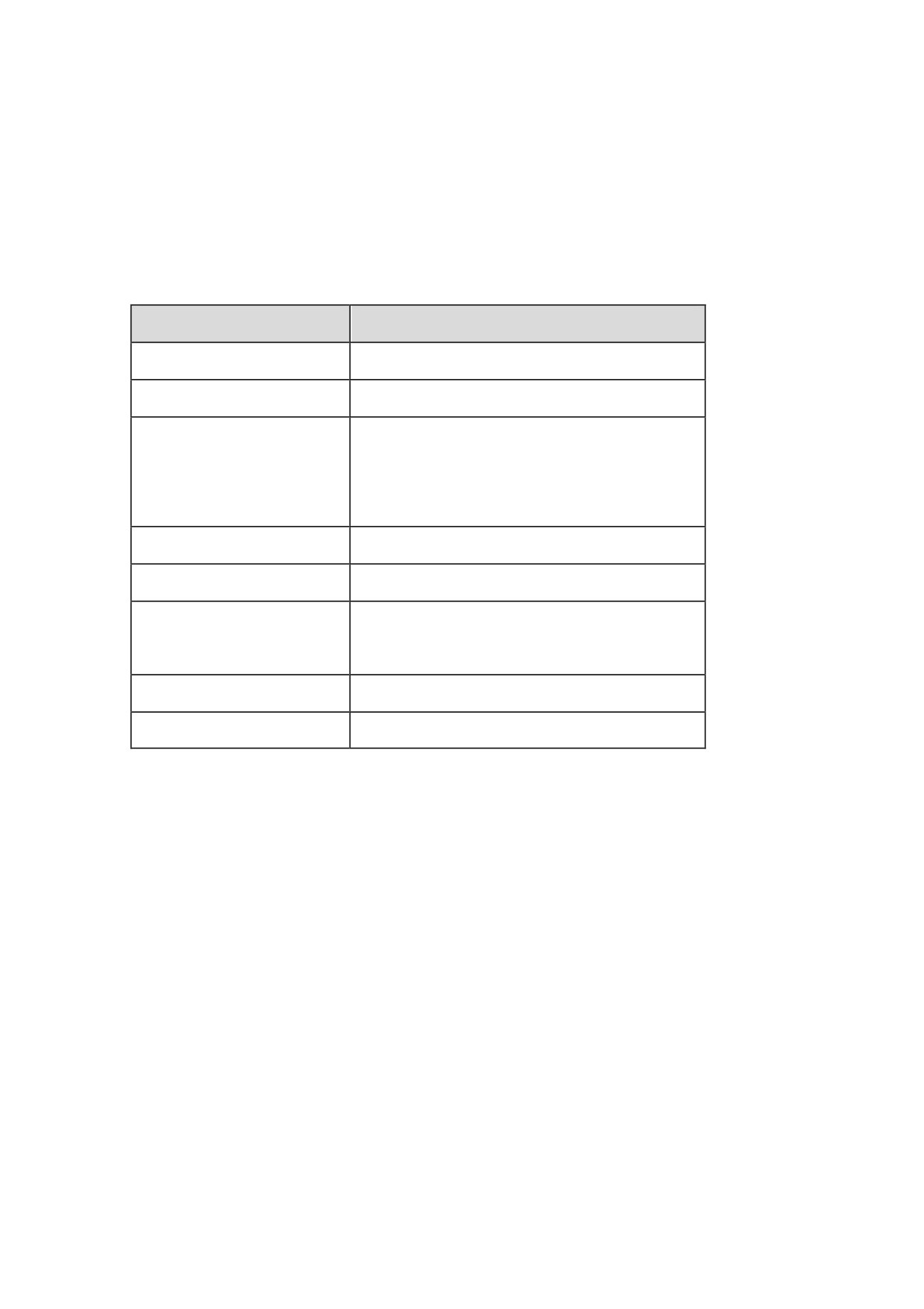
The table below describes the environmental requirements:
Items
Description
Working temperature (ºC)
0 to +45, non-freezing
Temperature change
< 1.1 ºC/min
Relative humidity
90% RH or lower (non-condensable)
Normal: 75% or lower
Short period (within a month): Max. 95%
Storage temperature (ºC)
-20 to +60, non-freezing
Storage humidity
Non-condensable
Surrounding environment
Indoor (non-exposed to sun), anti-sepsis,
anti-burning, anti-fog, anti-dust
Height
A maximum of 2000 meters above sea level
Vibration (m/s)
10 to 60 Hz: 5.9 (0.6G) or lower
6.2 Grounding
Correct grounding is critical for the numerical control unit and other electrical devices. Correct
grounding may:
1.
Protect operators from electric shock or injury caused by no grounding or incorrect
grounding.
2.
Protect the electrical devices from inductive interference which may lead to errors or
unexpected results.
When installing machine, reliable grounding must be provided. The neutral line in the power grid
cannot be used as the grounding line, otherwise, it may cause device damage or abnormal
operation, or even casualties.
71
User Operation and Maintenance Information
6.3 Power Conditions
The power supply of HNC turning system is provided by the electric cabinet. For more
information about machine power supply, see the installation guide of the machine.
6.4 Clean Fan Filter
Filters are used on cooling fans to prevent dust from entering into devices. However, it may
prevent adequate cooling if the filters become clogged. It is recommended to clean the filters
every three months. In dusty environments, clean the filters more often.
6.5 Operations After Being Left Unused
After a long period of being left unused, numerical control devices should be cleaned and dried, so
should the wiring and ground connections. Once power is resumed after being left unused, observe
the operation for several hours to make sure there is no problem.
72
Appendix 1 Parameter Settings
7 Appendix 1 Parameter Settings
This section describes the parameter structure and settings of Century Star HNC turning system.
7.1 Overview
You need to understand the function of a specific parameter and its original value before
modification. Incorrect parameter settings or modification may cause critical unexpected results.
The modification takes effect only after the CNC system restarts.
Common terms and descriptions:
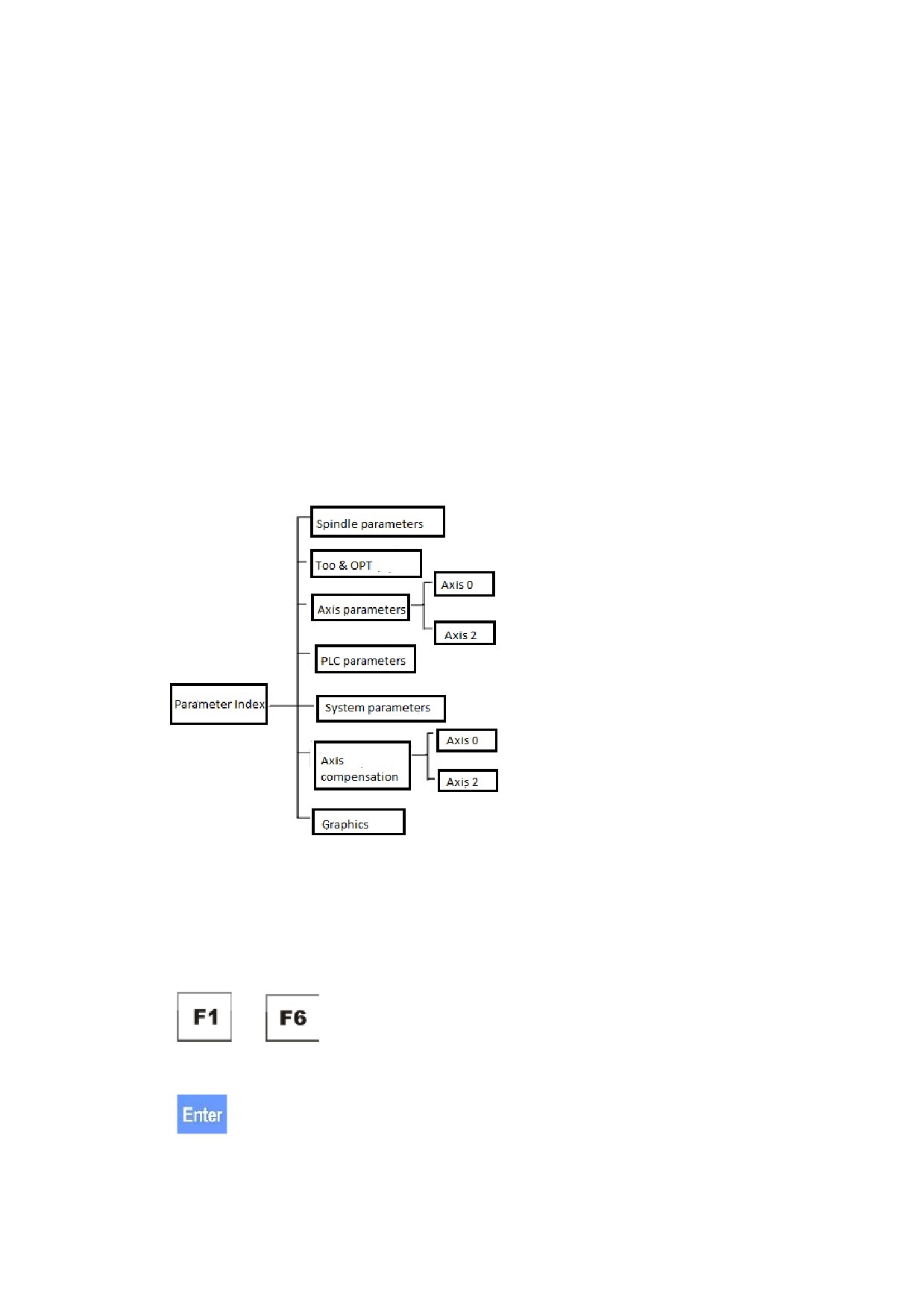
Parameter tree: consists of multiple levels of parameters. See the figure below:
Figure 7.1 Parameter tree
Window: An area where to display and modify parameter values.
Common functional buttons to check and modify parameters:
1.
to
: Enters corresponding menus and windows to achieve specific
functions.
2.
:
a.
Confirms to modify parameters.
73
Appendix 1 Parameter Settings
b.
Confirms the entered content.
3.
,
,
, and
: moves the cursor or cursor bar within a
menu or window.
4.
and
: shifts the page up or down.
7.2 Check and Set Parameters
Under
, you may press
and input a correct password to enter the parameter
window. See the figure below:
Figure 7.2 Parameter window
Follow the instructions below to check parameters and perform settings:
1. Press the
and
keys to select the parameter type to be edited, and then
press the
key to select the parameter to be edited. The parameter information is
displayed in the lower corner of the window.
74
Appendix 1 Parameter Settings
2. Press the
and
keys to select the parameter to be checked or set. Press
or
to shift the page up or down.
3. Press
to enter the parameter settings mode (The cursor blinks besides the parameter
value).
4. Enter a required parameter value.
5. Press the
key,
6. Press F4
after modifying all required parameters.
7. Repower the CNC system after successful saving so that the modification takes effect.
7.3 Detailed Parameter Description
7.3.1 Spindle Parameters
y
Spindle Encoder RPM [CNC factory]
Value: -32768 to 32767, default value: 1024
Description: The pulse number fed back from the encoder to the numerical control device
after each revolution of the spindle.
y
Total Spindle Shelf Number [user]
Value: -32768 to 32767, default value: 1
Description: The total shelf number of the spindle.
y
Shelf with Arrival Signal [user]
Value: 0, 1
Description: The value 0 indicates no spindle shelf arrival signal while 1 indicates that there
is spindle shelf arrival signal.
y
Spindle Brake Support [user]
Value: 0, 1
Description: The value 0 indicates that the spindle does not support brake while 1 indicates
75
Appendix 1 Parameter Settings
that the spindle supports brake.
y
Max. Time for Spdl-Speed Reached [user]
Unit: Millisecond
Value: 0 to 32767, default value: 4
Description: The maximum time to receive the signal that the spindle reaches a specific
speed.
y
Max.Speed of Second Spindle [user]
Unit: Revolution(s) Per Minute (rpm)
Value: 0 to 32767, default value: 3000
Description: The theoretical maximum speed of the second spindle motor under 10V
voltage.
y
Min.Value of DA [user]
Value: -32768 to 32767, default value: 0
Description: The minimum digital and analog (DA) value of the spindle voltage from 0 to
10V.
y
Threshold of DA [user]
Value: -32768 to 32767, default value: 0
Description: The DA threshold value of the spindle voltage from 0 to 10V.
y
Enable Indivi-Spdl Output [user]
Value: 0 to 32767, default value: 0
Description: The value 18 indicates that there is individual Spindle Enable output point
while other values indicates that there is no individual Spindle Enable output point.
y
Enable Spindle Output Point [user]
Value: 0 to 32767, default value: 0
Description: The value 0 indicates no output point while other values indicate signal point.
For example, 23 indicates Y2.3.
y
Zero Speed Threshold [user]
Unit: rpm
Value: 0 to 32767, default value: 50
76
Appendix 1 Parameter Settings
Description: The actual spindle speed lower that this value is considered as the zero speed
status.
y
Error Between Cmd. And Act. Speed [user]
Value: 0 to 32767, default value: 20
Description: The difference value, in percentage, between the spindle command speed and
actual speed. If the difference value is set to 0, then the spindle speed is reached when the
detected spindle speed reaches the value specified by Zero Speed Fluctuating Value,
y
Spindle Brake Wait Time [user]
Unit: Millisecond (ms)
Value: 0 to 32767, default value: 0
Description: The interval from receiving spindle stop command to outputting brake signal.
y
Spindle Brake Duration [user]
Unit: ms
Value: 0 to 32767, default value: 0
Description: The duration during which the spindle brake status is maintained. The brake
will be released when the duration exceeds this value.
y
Original Manual Spdl-Speed [user]
Unit: rpm
Value: 0 to 32767, default value: 300
Description: The default spindle speed after power on.
y
Max. Detected Speed at Shelves 1/2/3/4 [user]
Unit: rpm
Value: 0 to 32767, default value: 0
Description: The theoretical maximum detected speed at each spindle shelf.
y
Min. Allowed Speed at Shelves 1/2/3/4 [user]
Unit: R rpm
Value: 0 to 32767, default value: 0
Description: The theoretical minimum speed at each spindle shelf.
y
Max. Allowed Speed at Shelves 1/2/3/4 [user]
77
Appendix 1 Parameter Settings
Unit: Revolution(s) Per Minute
Value: 0 to 32767, default value: 0
Description: The theoretical maximum speed at each spindle shelf.
y
Initial Spindle Override [user]
Unit: percentage (%)
Value: 0 to 150, default value: 0
Description: The initial spindle override ratio after power on.
y
Star/Triangle Start [user]
Value: 0, 1
Description: The value 0 indicates that star/triangle start is not supported while 1 indicates
that star/triangle start is supported.
y
Switch Interval Time [user]
Unit: ms
Value: 0 to 32767, default value: 2
Description: The interval for the spindle switching from star output to triangle output.
y
Star Output Point [user]
Value: 0 to 32767, default value: 0
Description: The value 0 indicates no output point while other values indicates signal points.
For example, the value 23 indicate Y2.3.
y
Triangle Output Point [user]
Value: 0, default value: 0
Description: The value 0 indicates no output point while other values indicates signal points.
For example, the value 23 indicate Y2.3.
y
Spindle negative 10V [user]
Value: 0, default value: 0, 1
Description: The value 0 indicates that the spindle analog voltage is 0 to 10V while 1
indicates that the spindle analog voltage is -10V to 10V.
y
Spindle Encoder Exists [user]
Value: 0, default value: 0, 1
78
Appendix 1 Parameter Settings
Description: The value 0 indicates that there is no feedback from the spindle encoder while 1
indicates that there is feedback from the spindle encoder.
y
Max Spindle Shift Time [user]
Unit: ms
Value: 0 to 32767, default value: 0
Description: The maximum duration for spindle shelf shift. If the shelf shift is not completed
within this specified value, an alarm will be reported.
y
Spindle Shift With Shake [user]
Value: 0, 1
Description: The value 0 indicates spindle shift without shake while 1 indicates spindle shift
with shake.
y
Spindle Reverse Mode [user]
Value: 0, 1
Description: The value 0 indicates counter-clockwise spindle rotation controlled by Y signal
while 1 indicates counter-clockwise rotation controlled by the positive and negative polarity
(-, +) of analog voltage.
y
Delay of Spindle Feedback Time [user]
Unit: ms
Value: 0 to 32767, default value: 0
Description: The delay allowed for spindle feedback.
y
Max. Tapping Speed [user]
Unit: rpm
Value: 0 to 32767, default value: 1000
Description: The allowed maximum spindle speed during tapping.
y
Min. Tapping Speed [user]
Unit: rpm
Value: 0 to 32767, default value: 0
Description: The allowed minimum spindle speed during tapping.
y
Pre-stop Tapping Numerator [user]
79
Appendix 1 Parameter Settings
Value: 1 to 32767, default value: 1
Description: The numerator of pre-stop tapping.
y
Pre-stop Tapping Temp-Numerator [user]
Value: 1 to 32767, default value: 1
Description: The temporary numerator for pre-stopping tapping.
y
Spindle Speed When Shield Open [user]
Unit: rpm
Value: 0 to 32767, default value: 0
Description: The spindle speed when the shield is open.
y
Specified Speed When Shift [user]
Unit: rpm
Value: 0 to 32767, default value: 0
Description: The revolution speed during spindle shelf shift.
y
Stop Spdl at ProgEnd[user]
Value: 0, 1
Description: The value 0 indicates to stop the spindle after the program ends while 1
indicates not to stop the spindle after the program ends.
y
Spindle Encoder Direction [user]
Value: 32, 33
Description: The value 32 indicates the spindle encoder direction is positive while 33
indicates the spindle encoder direction is negative.
7.3.2 Tool & OPT
y
Tool Positions [user]
Value: 4, 6, 8, others
Description: The value 4, 6, or 8 indicates the tool station number on the turret, while others
indicates the turret type is Horizon.
y
Tool Change Duration [user]
Unit: ms
Value: 0 to 32767, default value: 6
80
Appendix 1 Parameter Settings
Description: The maximum duration allowed for tool change. If the tool change exceeds this
specified duration, an alarm will be reported.
y
Turret Delay Time [user]
Unit: ms
Value: 0 to 32767, default value: 50
Description: The delay for turret clockwise rotation.
y
Turret Brake Time [user]
Unit: ms
Value: 0 to 32767, default value: 1000
Description: The delay for turret counter clockwise rotation.
y
Chuck Type [user]
Value: 0, 1, 2
Description: The value 0 indicates Manual, 1 indicates Persistent, while 2 indicates Pulse.
y
Protection Door [user]
Value: 0, 1
Description: The value 0 indicates not supporting protection door while 1 indicates
supporting protection door.
y
Sleeve [user]
Value: 0, 1
Description: The value 0 indicates not supporting sleeve while 1 indicates supporting sleeve.
y
Initial Chuck Mode [user]
Value: 0, 1
Description: The value 0 indicates external chuck while 1 indicates internal chuck.
y
Turret Brake Signal [user]
Value: 0, 1
Description: The value 0 indicates no turret brake signal while 1 indicates there is turret
brake signal.
y
T-Code Pre-Finished Delay[user]
Unit: ms
81
Appendix 1 Parameter Settings
Value: 0 to 32767, default value: 0
Description: The delay of pre-finishing the T-command. The value 0 indicates invalid.
y
Tool Arrival Signal Always [user]
Value: 0, 1
Description: The value 0 indicates not to detect tool arrival signal while 1 indicates to always
detect tool arrival signal.
y
Chuck Signal [user]
Value: 0, 1
Description: The value 0 indicates no chuck clamping and releasing arrival signal while 1
indicates chuck clamping and releasing arrival signal.
y
Turret Direction [user]
Value: 0, 1
Description: The value 0 indicates positive X-axis pointing down while 1 indicates positive
X-axis pointing up.
7.3.3 Feed Axis Parameters (X axis)
y
Axis Type [user]
Value: 0, 1, 2, 3
Description: The value 0 indicates no axis, 1 indicates Linear axis, while 2 and 3 indicates
rotation axis.
y
External Pulse Equivalent Numerator and External Pulse Equivalent Denominator
[machine factory]
Value: -32768 to 32767, default value: 1
Description: The value of External Pulse Equivalent Numerator/External Pulse Equivalent
Denominator is the actual pulse equivalent, that is, the actual axis motion distance
corresponding to each position unit, or the system electric gear rate.
The unit of the external pulse equivalent numerator is micrometer (μm), and there is no unit
for the external pulse equivalent denominator.
External pulse equivalent numerator (μm)
Machine motion distance per motor revolution (μm)
External pulse equivalent denominator
Pulse sent by CNC per motor revolution
82
Appendix 1 Parameter Settings
Users may change the electric gear rate by setting the external pulse equivalent numerator
and the external pulse equivalent denominator, or change the motor rotation direction by
changing the positive or negative symbol (-, +) of the electric gear rate.
Example:
GK Series servo motor (2500 threads encoder) with HSV-16D driver; screw: 6 mm; gear rate:
2: 3
Then after each motor revolution, the CNC system will send 40000 pulses (quadruple
frequency for motor encoder and four-point subdivision for command, thus sent pulses =
2500*4*4=40000). The machine moves 4 mm (6 mm *2/3 = 4 mm), that is 4000 μm.
Therefore, the value of External Pulse Equivalent Numerator/External Pulse Equivalent
Denominator is 1/10 (4000/40000=1/10).
It is equivalent to set the External Pulse Equivalent Numerator to 1 and External Pulse
Equivalent Denominator to 10, or to set the External Pulse Equivalent Numerator to 2 and
External Pulse Equivalent Denominator to 20.
y
Positive Software Limit [machine factory]
Unit: Micrometer (μm)
Value: -2147483648 to 2147483647, default value: 8000000
Description: The positive software limit point. This parameter value takes effect only after
the machine homes to the reference point.
y
Negative Software Limit [machine factory]
Unit: μm
Value: -2147483648 to 2147483647, default value: 8000000
Description: The negative software limit point. This parameter value takes effect only after
the machine homes to the reference point.
y
REF Direction [machine factory]
Value: -, +
Description: The initial motion direction of axis to reference point after corresponding
reference command is sent. If users have pressed the button for homing the axis to the
reference point when the corresponding command is sent, the initial motion direction
83
Appendix 1 Parameter Settings
depends on the mode for homing to the reference point.
y
Reference Point Position [machine factory]
Unit: μm
Value: -2147483648 to 2147483647, default value: 0
Description: The coordinate position of the reference point in the machine coordinate system.
Generally, the origin point of the machine coordinate system is set as the reference point.
Therefore the reference point is generally set to 0.
y
Reference Point Offset [machine factory]
Unit: μm
Value: -32768 to 32767, default value: 0
Description: When homing to the reference point, after the axis reaches the Z pulse, the point
will not be defined as the reference point. The axis will continue to move a distance
specified by this value, and then the point will be defined as the reference point.
y
Rapid Traverse Speed at RER [machine factory]
Unit: Millimeter/Minute
(mm/min)
Value: 0 to 65535, default value: 500
Description: The rapid traverse speed before the reference point key is pressed.
Note: This value must be smaller than the maximum rapid traverse speed.
If this speed is set too fast, the distance between the reference point switch and nearby limit
switch (positive limit switch) cannot be too small. Otherwise, an over-limit alarm will be
reported and the system fails to home to reference point if the speed for homing to the
reference point is too fast to speed down and the limit switch is pressed.
In addition, the effective travel distance to the reference point cannot be too short, otherwise,
the system may fail to home to the reference point if the speed for homing to the reference
point is too fast to speed down before crossing the reference point.
y
Positioning Speed at REF [machine factory]
Unit: mm/min
Value: 0 to 65535, default value: 200
Description: The positioning speed after the reference point key is pressed.
84
Appendix 1 Parameter Settings
Note: This parameter value must be less than the value specified by Rapid Traverse Speed
at RER.
y
Unidirectional Positioning Offset [machine factory]
Unit: μm
Value: -32768 to 32767, default value: 1000
Description: In the unidirectional positioning mode of G60 workstation, the difference value
between the speed slowdown point and the positioning point when the rapid traverse speed
changes to the positioning speed.
Uni-direct Positioning Offset > 0: positive positioning
Uni-direct Positioning Offset < 0: negative positioning
y
Maximum Rapid Traverse Speed [machine factory]
Unit: mm/min
Value: 0 to 65535, default value: 1000
Description: The maximum rapid positioning speed of G00 (no processing) When the
override ratio of Rapid Traverse Speed reaches the maximum.
Note: The value of Maximum Rapid Traverse Speed must be the largest value among all
speed values of the axis. The value of Maximum Rapid Traverse Speed is very closely
related to the value of External Pulse Equivalent Numerator and External Pulse
Equivalent Denominator. You need to properly define this value to make sure the value
does not exceed the motor revolution speed range. For example, if the rated speed of the
motor is 2000 rpm, and connected to a ball screw that is six millimeter away from the screw
with a pair of synchronous gear belts whose gear ratio is 2: 3, then the maximum rapid
traverse speed cannot exceed 8000 mm/min (≤ 2000 * (2/3) * 6 = 8000).
y
Maximum Feedrate [machine factory]
Unit: mm/min
Value: 0 to 65535, default value: 500
Description: The maximum feed rate allowed by the executed commands (e.g G01, G02)
under certain precision conditions.
Note: This parameter value is related to processing requirements, mechanical transmission
85
Appendix 1 Parameter Settings
and load. The maximum feed rate must be less than the maximum rapid traverse speed.
y
Jerk Time for Rapid Traverse [machine factory]
Unit: ms
Value: 0 to 800, default value: 64
Description: The time when the speed increases from 0 to 1 m/min or from 1 m/min to 0
during G00 positioning (no processing). The larger the time constant is, the slower the
acceleration and deceleration.
Note: This value depends on the motor size, the driver performance, and the load. It is
generally between 32 to 150. For example, the servo motor is generally 32 and the stepper
motor is 64.
y
Jerk for Rapid Traverse [machine factory]
Unit: ms
Value: 0 to 150, default value: 32
Description: The acceleration time constant during rapid traverse, which is generally 16, 32,
or 64. The larger the time constant is, the slower the acceleration.
Note: This value depends on the motor size, the driver performance and the load. It is
generally between 16 to 100. For example, the servo motor is generally 16 and the stepper
motor is 32.
y
Jerk Time for Machining [machine factory]
Unit: ms
Value: 0 to 800, default value: 64
Description: The time when the speed increases from 0 to 1 m/min or from 1 m/min to 0
during processing (G01, G02…). The larger the time constant is, the slower the acceleration
and deceleration.
Note: This value depends on the processing requirements and load, the motor size, the driver
performance and the load. It is generally between 32 to 150. For example, the servo motor is
generally 32 and the stepper motor is 64.
y
Jerk for Machining [machine factory]
Unit: ms
86
Appendix 1 Parameter Settings
Value: 0 to 150, default value: 32
Description: The acceleration time constant during processing, which is generally 16, 32, or
64. The larger the time constant is, the slower the acceleration.
Note: This value depends on the motor size, the driver performance and the load. The value
generally ranges between 16 and 100. For example, the servo motor is generally 16 and the
stepper motor is 32.
y
Positioning Tolerance [machine factory]
Unit: μm
Value: 0 to 255, default value: 20
Description: The maximum allowed positioning error.
Note: This value depends on the motor size, the driver performance and the load. The value
generally ranges between 10 and 50. If the value is too small, the system may not reach the
positioning tolerance value and stop the motor. If the value is too large, the processing
precision may be affected. Generally, the larger the machine is, the larger this value is. The
lower the machine transmission and precision is, the larger this value is.
If a stepper motor is used, it is recommended that you set the value to integral multiple of the
movement distance corresponding to each step.
y
Servo Type [machine factory]
Value: 45, 46, default value: 45
Description: Set this value to 45 for the servo motor that uses pulse interface with feedback.
Set this value to 46 for the servo motor that uses pulse interface without feedback (e.g
stepper servo motor).
y
Maximum Track Error [CNC factory]
Unit: μm
Value: 0 to 65535, default value: 12000
Description: This parameter is used to report an alarm if the track error exceeds the specified
value. The value 0 indicates no track error alarm. This parameter must be set based on the
maximum speed and servo loop hysteresis properties. See the following expressions
(approximate formula):
87
Appendix 1 Parameter Settings
Maximum speed * (10000 - position loop feedforward coefficient * 0.7)/position loop
proportional coefficient/3
Unit:
a.
Maximum track error: um
b.
Maximum speed: mm/min
c.
Position loop feedforward coefficient: 1/10000
d.
Position loop proportional coefficient: 0.01 1/s
y
Pulses per Motor Revolution [CNC factory]
Value: 0 to 65535, default value: 10000
Description: The pulse count received by the CNC system per motor revolution. That is, the
pulses fed back from the servo system or the servo motor to the CNC system. As the system
has four subdivision,
the value of Pulses per Motor Revolution = the actual pulse count of the servo m otor position encoder x 4
y
Stepper Motor Pulses [CNC factory]
Value: 0 to 65535, default value: 0
Description: e.g. If the pulse of a two-phase stepper motor is 4, then this value should be set
to 4.
y
E-Gear Rate Numerator (0 for no feedback) [CNC factory]
Value: 0 to 65535, default value: -4
Description: Set this parameter to 0 if no feedback is required.
y
E-Gear Rate Denominator (0 for no feedback) [CNC factory]
Value: 0 to 65535, default value: 1
Description: Set this parameter to 0 if no feedback is required.
E-Gear Rate Numerator/E-Gear Rate Denominator = CNC system command/position value
fed back by the servo motor to the CNC system
This is used to adjust the situation when the CNC command is inconsistent with the
feedback information. As the system has four subdivision, these two parameter values are
generally 4: 1 or -4: 1 if the feed driver does not perform multiplication or subdivision
frequency for CNC commands.
88
Appendix 1 Parameter Settings
y
Enable Zero-Pulse Input [CNC factory]
Value: 0, 1
Description: The value 0 indicates to disable Zero-Pulse Input while 1 indicates to enable
Zero-Pulse Input.
y
Stepper Motor [CNC factory]
Value: 0, 1
Description: The value 0 indicates non-stepper motor while 1 indicates stepper motor
7.3.4 PLC Parameters
y
REF Alarm [CNC factory]
Value: 0, 1
Description: The value 0 indicates no alarm is reported when the feed axis is not homed to
the original point after power on, while 1 indicates an alarm is reported when the feed axis is
not homed to the original point after power on and the work mode cannot switch to the Auto
or Single Block mode.
y
MPG Axis Chosen [CNC factory]
Value: 0, 1
Description: The value 0 indicates no axis selection for MPG while 1 indicates axis selection
is provided for MPG.
y
Installed Home Dog [CNC factory]
Value: 0, 1
Description: The value 0 indicates no Home Dog is installed and the floating reference point
automatically takes effect, while 1 indicates the Home Dog is installed.
y
Lubrication Off Time [CNC factory]
Unit: ms
Value: 0 to 32767, default value: 0
Description: The duration during which the lubrication function is disabled.
y
Lubrication On Time [CNC factory]
Unit: ms
Value: 0 to 32767, default value: 0
89
Appendix 1 Parameter Settings
Description: The duration during which the lubrication function is enabled.
y
Lubrication Alarm Detection Delay [CNC factory]
Unit: ms
Value: 0 to 32767, default value: 0
Description: If no lubrication signal is detected when the duration exceeds this value, an
alarm will be reported.
y
Lubrication Mode [CNC factory]
Unit: meter (m)
Value: 0, other values; default value: 0
Description: The value 0 indicates lubrication based on time while other values indicates
lubrication based on distance.
y
Hydraulic Alarm Detection Delay [CNC factory]
Unit: ms
Value: 0 to 32767, default value: 0
Description: If hydraulic alarm signal is constantly detected during this specified duration,
an alarm will be reported.
y
Initial Rapid Override [CNC factory]
Unit: %
Value: 0 to 100
Description: The initial rapid override ratio after power on.
y
Each Axis Limited [CNC factory]
Value: 0, 1
Description: The value 0 indicates no independent axis limit for each axis and all axis use
the same input point (X2.0), while 1 indicates independent axis limit for each axis.
y
MPG Pulse Reverse [CNC factory]
Value: 0, 1
Description: When the actual axis motion direction is in the opposite direction of the MPG
command, you may set this parameter value to 1 to change the direction.
y
Mach-Brake Includes MST [CNC factory]
90
Appendix 1 Parameter Settings
Value: 0, 1
Description: The value 0 indicates the MST function is available after machine brake while 1
indicates the MST function is unavailable after machine brake.
y
Rapid Jog Feed Has SelfLock [CNC factory]
Value: 0, 1
Description: The value 0 indicates no self-lock for rapid jog feed while 1 indicates available
self-lock for rapid jog feed.
y
(Lathe: X Mill: Z) Wait Time for Brake Signal [CNC factory]
Unit: ms
Value: 0, other values
Description: The value 0 indicates no brake while other values indicates the wait time before
the brake signal is output.
y
MPG Coding Form [CNC factory]
Value: 0, 1
Description: The value 0 indicates independent MPG coding form while 1 indicates
compound MPG coding form.
y
Manual Speed of Feed [CNC factory]
Value: 1 to 10, default value: 1
Description: The value 1 indicates the minimum manual feed speed while 10 indicates the
maximum manual feed speed.
y
Speed to Floating Origin [CNC factory]
Value: 1 to 10; default value: 1
Description: The value 1 indicates the minimum speed for homing to the floating origin
point while 10 indicates the maximum speed.
y
No MCP Stop Signal [CNC factory]
Value: 0, 1
Description: The value 0 indicates to detect the MCP Stop signal while 1 indicates not to
detect the MCP Stop signal.
y
No MPG Stop Signal [CNC factory]
91
Appendix 1 Parameter Settings
Value: 0, 1
Description: The value 0 indicates to detect the MPG Stop signal while 1 indicates not to
detect the MPG Stop signal.
y
No Drivers Ready Signal [CNC factory]
Value: 0, 1
Description: The value 0 indicates to detect the driver ready signal while 1 indicates not to
detect the driver ready signal.
y
No Limit Alarm Signal [CNC factory]
Value: 0, 1
Description: The value 0 indicates to detect the limit alarm signal while 1 indicates not to
detect the limit alarm signal.
y
No External Alarm Signal [CNC factory]
Value: 0, 1
Description: The value 0 indicates to detect the external alarm signal while 1 indicates not to
detect the external alarm signal.
y
No Spindle Alarm Signal [CNC factory]
Value: 0, 1
Description: The value 0 indicates to detect the spindle alarm signal while 1 indicates not to
detect the spindle alarm signal.
y
Fluctuate Zero Lose [CNC factory]
Value: 0, 1
Description: The value 0 indicates to detect the floating origin loss signal while 1 indicates
not to detect the floating origin loss signal.
7.3.5 System Parameters
y
Color (0, 1, 2, 3) [User]
Value: 0, 1, 2, 3
Description: The value 0 indicates the default color while 1, 2, 3 indicate three specific
colors.
y
Initial Interface (0, 1) [User]
92
Appendix 1 Parameter Settings
Value: 0, 1
Description: The value 0 indicates the program interface while 1 indicates the macro
variables settings interface.
y
Status (0-7) [User]
Value: 0 to 7
Description: The value indicates the number of the group that requires status monitoring.
y
Language [User]
Value: 0, 1
Description: The value 0 indicates Chinese while 1 indicates English.
y
Register mode [User]
Value: 0, 1
Description: The value 0 indicates registration through keyboard input while 1 indicates
registration through USB files.
y
Y-axis [User]
Value: 1, -1
Description: The value 1 indicates to install Y-axis while -1 indicates not to install Y-axis.
y
C-axis [User]
Value: 5, -1
Description: The value 5 indicates to install C-axis while -1 indicates not to install C-axis.
y
Diameter/Radius at X (1/0) [User]
Value: 0, 1
Description: The value 0 indicates radius programming while 1 indicates diameter
programming.
y
Metric/Inches (1/0) [User]
Value: 0, 1
Description: The value 0 indicates Metrics programming while 1 indicates Inches
programming.
y
Power Off Protection [User]
Value: 0, 1
93
Appendix 1 Parameter Settings
Description: The value 1 indicates to use power off protection while 0 indicates not to use
power off protection.
y
Coord Display [User]
Value: 0, 1
Description: The value 0 indicates command value while 1 indicates the actual value.
y
Show time [User]
Value: 0, 1
Description: The value 0 indicates not to display system time while 1 indicates to display
system time.
y
Pulse Type [User]
Value: 0, 1, 2
Description: The value 0 indicates single pulse, 1 indicates dual-pulse, while 2 indicates AB
phase orthogonal pulses.
y
Metric Precision [User]
Value: 0, 1
Description: The value 0 indicates three digits after the decimal point while 1 indicates four
digits after the decimal point.
y
Inches Precision [User]
Value: 0, 1
Description: The value 0 indicates three digits after the decimal point while 1 indicates four
digits after the decimal point.
y
CF Card [User]
Value: 0, 1
Description: The value 0 indicates to support CF card while 1 indicates not to support CF
card.
y
Original Speed of MDI [User]
Unit: mm/min
Value: 0 to 32767, default value: 500
Description: The feed speed of the running program when no feed rate value is specified
94
Appendix 1 Parameter Settings
under MDI.
y
Wear Out Accumulation [User]
Value: 0, 1
Description: The value 0 indicates tool wear accumulation while 1 indicates no tool wear
accumulation.
y
Workpiece Counting [User]
Value: 0, 1
Description: The value 0 indicates that the command M30 makes the completed workpieces
accumulation while 1 indicates that the command M64 makes the completed workpieces
accumulation.
y
G94/G95 [User]
Value: 0, 1
Description: The value 0 indicates the initial program mode is G94 while 1 indicates the
initial program mode is G95.
y
Protection-Mode [User]
Value: 0, 1, 2
Description: The value 0 indicates not to enable the program editing protection. The value 1
indicates to enable the program editing protection. In this case, you cannot edit or create a
program. The value 2 indicates no program display.
y
Check wear value in real time [User]
Value: 0, 1
Description: The value 0 indicates not to check the wear value in real time while 1 indicates
to check the wear value in real time.
y
Tool's offset only in Jog [User]
Value: 0, 1
Description: The value 0 indicates No while 1 indicates Yes.
7.3.6 Axis Compensation (X-axis)
y
Reversed Gap [machine factory]
Unit: μm
95
Appendix 1 Parameter Settings
Value: 0 to 65535, default value: 0
Description: The measured value in the workspace of the machine. This value can be set to 0
if bidirectional pitch compensation is used.
y
Pitch Comp. Type [machine factory]
Value: 0, 1, 2, default value: 0
Description: The value 0 indicates no pitch compensation; 1 indicates unidirectional; 2
indicates bidirectional.
y
Number of Compensation [machine factory]
Value: 0 to 127 (0 to 5000), default value: 0
Description: The number of pitch offset compensation. For unidirectional compensation, the
maximum number is 128; for bidirectional compensation, the maximum number is 64.
y
Index of Reference Point [machine factory]
Description: The sequencing index of the reference point in the offset table.
Sequencing rule: Based on the position of each compensation point in the coordinate system,
sequencing from the negative direction to the positive direction and starting from 0.
Example:
a.
If the compensation points are -180, -120, -60, 0, and the reference point is 0, then the
index of the reference point is 3.
b.
If the compensation points are 0, -60, -120, -180, and the reference point is 0, then the
index of the reference point is 0.
y
Pitch Compensation Point Interval [machine factory]
Unit: um
Value: 0 to 4294967295, default value: 0
Description: The distance between two adjacent compensation points.
y
Offset [machine factory]
Unit: μm
Value: -32768 to 32767, default value: 0
Description: The absolute compensation.
Offset= machine command value - machine actual value
96
Appendix 1 Parameter Settings
The difference value between the actual value moved on the axis and the
command value, that is, the value the tool need to move further or less to make
the tool move to the accurate position on the axis.
For bidirectional pitch compensation, you need to enter correct positive pitch
offset value first, and then enter negative pitch offset value. The compensation
value (positive and negative) must be entered based on the position of the
compensation point in the machine coordinate system and based on the axis
direction. For example, for the two points (-150 and -100), you need to enter the
pitch offset value for -150 first and then for -100. In this case, the offset index
for -150 is on top of -100.
Example: If there are ten compensation points, and bidirectional pitch compensation is used,
then 0 to 9 are positive compensation values, and 10 to 19 are negative compensation.
Example:
If the command machine coordinate value is 100 mm and the actual machine coordinate
value is 100.01mm,then the offset is -10 μm (100 - 100.01 = -0.01mm = -10 μm).
You need to pay attention to the symbols of the axis value when calculating offset value. For
example, if the command machine coordinate value is -100 mm and the actual machine
coordinate value is -100.01mm, then the offset is 10 μm (-100 - (-100.01) = 0.01mm = 10
μm)
The following information describes the pitch compensation method:
Known conditions:
a.
X axis, the reference value 0
b.
Homing to reference in the positive direction
c.
positive software limit: 2000 (2mm)
d.
Negative software limit: -602000 (-602 mm)
e.
Compensation interval within travel: 40 mm
f.
Compensation point: (600/40) + 1 = 16
g.
Compensation point coordinate value (from left to right): -600, -560, -520, -480, -440,
-400, -360, -320, -280, -240, -200,-160, -120, -80, -40, 0
97
Appendix 1 Parameter Settings
If the reference point value is 0, then the index of reference point is 15.
The procedure for pitch offset measurement is as below:
%0110: File header
G92 X0 Y0 Z0: Set temporary coordinate (should start from the reference point)
WHILE [TRUE]: Infinite loop (endless loop)
G91 X1 F2000: Positively move 1 millimeter on the X-axis
G04 P4 : Pause for four seconds
G91 X-1: Negatively move 1 millimeter on the X-axis and return to the measurement
position, and then clear the reverse gap
: The measurement system is cleared.
G04 P4 : Pause for four seconds, and the measurement system records data.
M98 P1111 L15: Activate the subprogram for negative movement 15 times, program No.:
1111
G91 X-1 F1000: Negatively move 1 millimeter on the X-axis
G04 P4 : Pause for four seconds
G91 X1: Positively move 1 millimeter on the X-axis and return to the measurement
position, and then clear the reverse gap
G04 P4 : Pause for four seconds and the measurement system records data.
M98 P2222 L15: Activate the subprogram for positive movement 15 times, program No.:
2222
ENDW : End of the loop program
M30: Stop and return
%1111: Subprogram for negative movement on the X-axis is 1111.
G91 X-40 F1000: Negatively move 40 mm on the X-axis
G04 P4 : Pause for four seconds and the measurement system records data.
M99: End of the subprogram
%2222: Subprogram for positive movement on the X-axis is 2222.
G91 X40 F500: Positively move 40 mm on the X-axis
G04 P4 : Pause for four seconds and the measurement system records data.
M99: End of the subprogram
98
Appendix 1 Parameter Settings
When measuring pitch offset, you need to set the reverse gap to 0 firstly. Before changing the
measurement direction, you need to clear the reverse gap of the coordinate.
The offset [0] to [15] are the offset values of the compensation points (-600, -560, -520, -480,
-440,-400, -360, -320, -280, -240, -200,-160, -120, -80, -40, 0) on the X-axis, moving in the
positive direction.
The offset [16] to [31] are the offset values of the compensation points (-600, -560, -520, -480,
-440,-400, -360, -320, -280, -240, -200,-160, -120, -80, -40, 0) on the X-axis, moving in the
negative direction.
7.3.7 Graphics
y
Graphics Amplification Coefficient [user]
Default value: 1.0
Description: The amplification coefficient for graphic display.
y
External Diameter [user]
Default value: 60.0
Description: The actual external diameter of the sample workpiece.
y
Internal Diameter [user]
Default value: 0.0
Description: The actual inner diameter of the sample workpiece.
y
Workblank Length [user]
Default value: 120.0
Description: The actual length of the rough workpiece.
y
Internal End Surface [user]
Default value: -120
Description: The actual inner end surface of the rough workpiece.
99