HNC-180xpT3. Operation Guide (V 2.0 2015.4) - page 2
Operation Modes and Display Screen
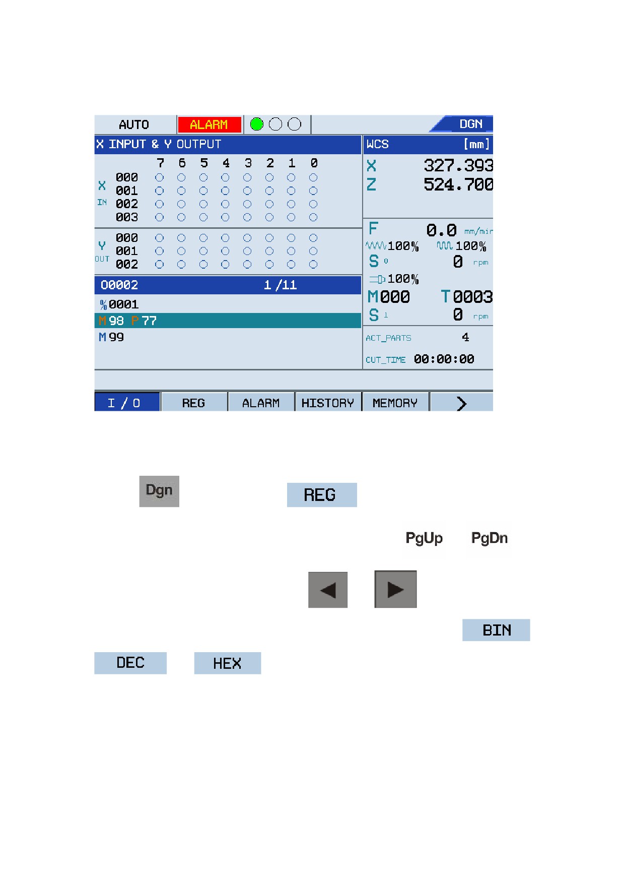
Figure 1.22 Check X input and Y output
2.
REG
Press the
key and then press F2
to enter its corresponding submenu.
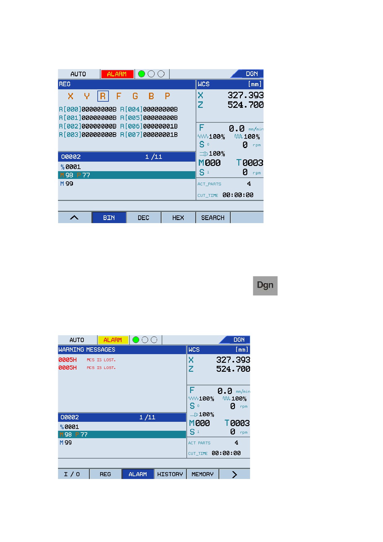
The system displays the X Register value by default. You may use the
or
key to view the values of other Registers. Press
and
to view the values of
Register Y, R, F, G, B, P. Press F1 to locate quickly the Register as required. Press
,
and
to switch between different display modes.
31
Operation Modes and Display Screen
Figure 1.23 Check Register status
3.
ALARM
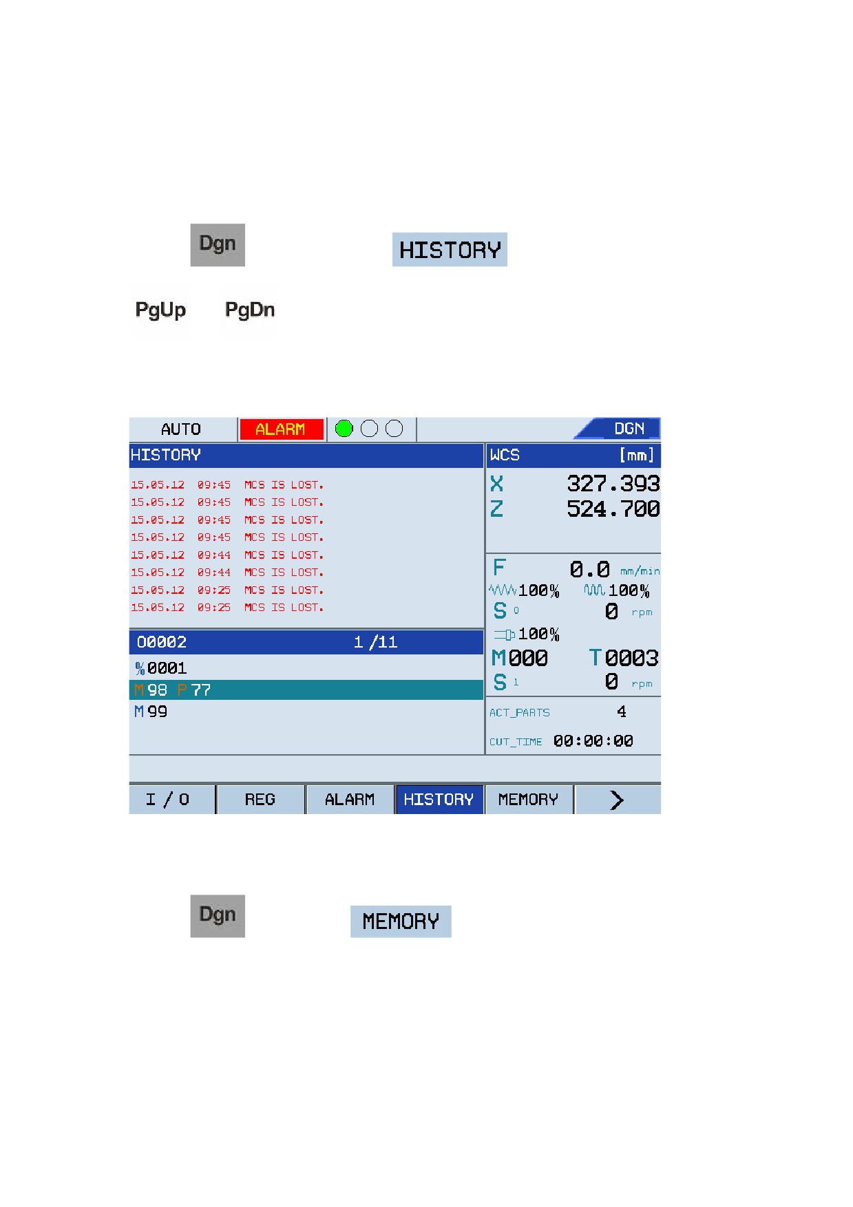
If an error occurs during system running or processing, the message "ALARM" will be displayed
on the screen, and the indicator blinks continuously. You may press the
key to check
the detailed warning messages. See the figure below:
Figure 1.24 Check warning messages
32
Operation Modes and Display Screen
You may perform related operations to restore the system operation based on the displayed alarm
information.
4.
HISTORY
Press the
key and then press F4
to check the alarm history. Press
or
to page up or down as required. This is used to analyze system trouble
history and perform related troubleshooting. See the figure below:
Figure 1.25 Check alarm history
5.
MEMORY
Press the
key and then F5
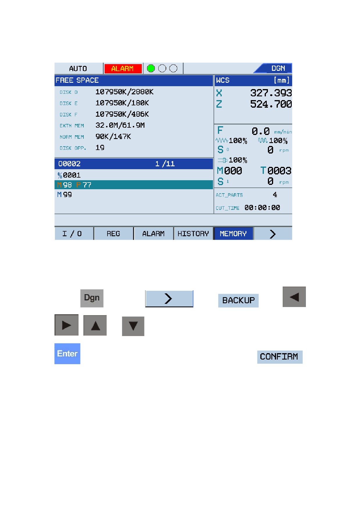
to enter its corresponding screen to check
the space and internal storage of each disk for the CNC system.
33
Operation Modes and Display Screen
Figure 1.26 Space and internal storage of each disk
6.
Extended
• Software Backup
Press the
key, select F6
, press F2
, use the
,
,
, and
keys to select the file required to back up, and then press the
key to confirm the selection. Specify the file type, and then press F5
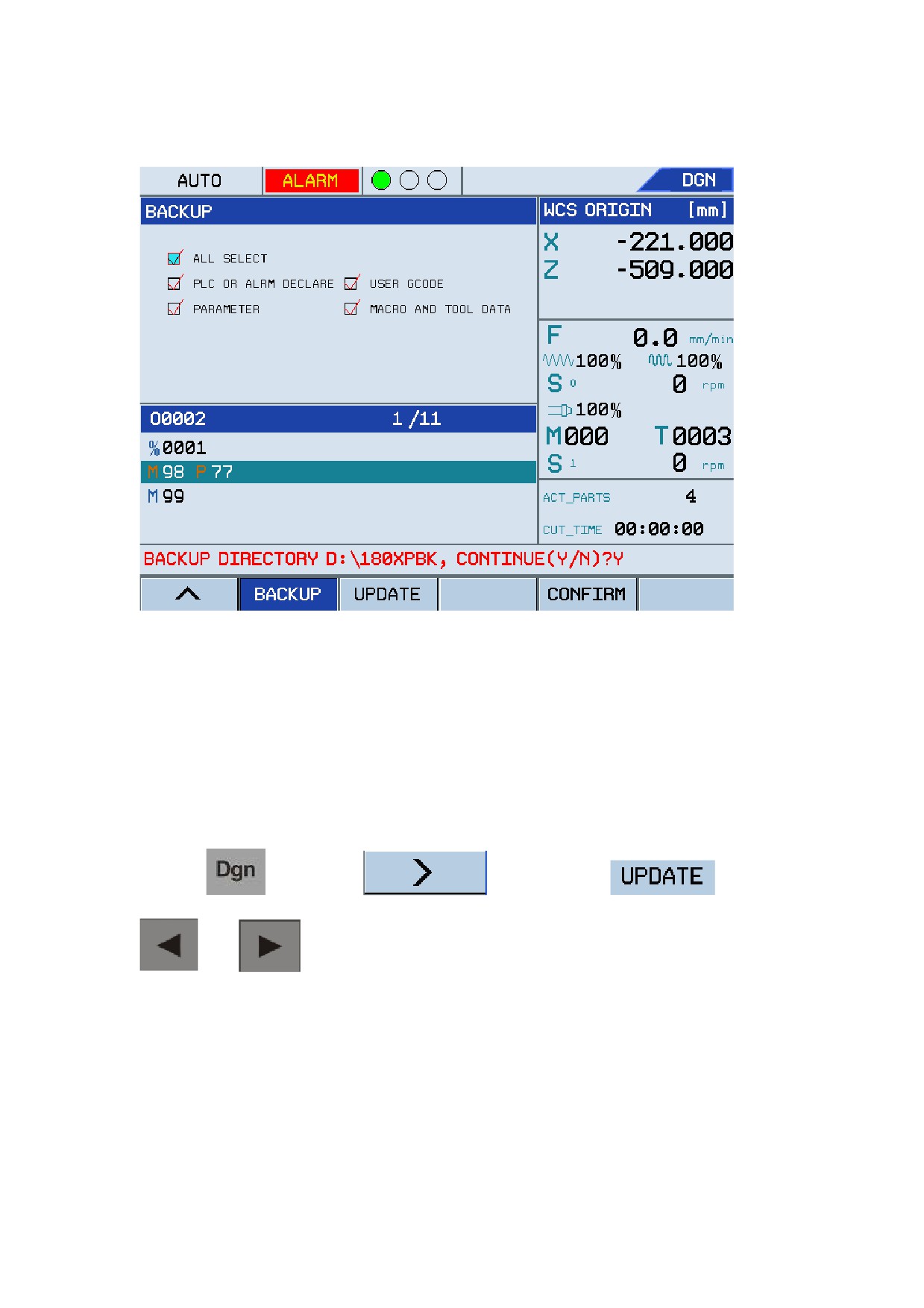
A message as shown in the figure below is displayed:
34
Operation Modes and Display Screen
Figure 1.27 Back up software
Note: The file backed up is saved in the 180XPBK folder in the USB flash disk by default. If there
is no external USB flask disk, the message "NO USB, UPDATE FUNCTION DISBALED!!!." is
displayed during backup.
• Software update
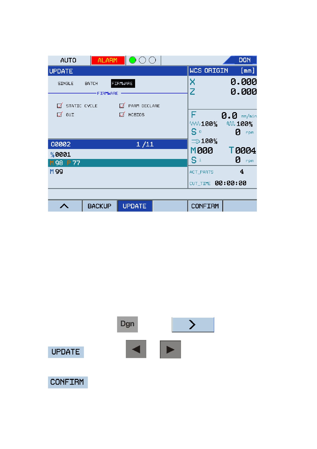
Software upgrade includes three kinds of updates: SINGLE, BATCH, and FIRMWARE.
Press the
key, select F6
, and then press F3
. Use the
and
keys to select "SINGLE", "BATCH", or "FIRWARE". See the figure
below:
35
Operation Modes and Display Screen
Figure 1.28 Software update
Note: If there is no external USB flask disk, the message "NO USB, UPDATE FUNCTION
DISBALED!!!." is displayed during update. Do not power off during update, otherwise the system
cannot start.
y Firmware update:
Firmware update intends to update the drive program, upper-layer software, lower-layer software,
and configuration file at one time. Firmware update is generally used to update the newly released
software.
To update firmware, press the
key, select F6
, press F3
, and then use the
and
keys to select FIRMWARE. Make
sure that the four files of Firmware are all selected (see Figure 1.28), and then press F5
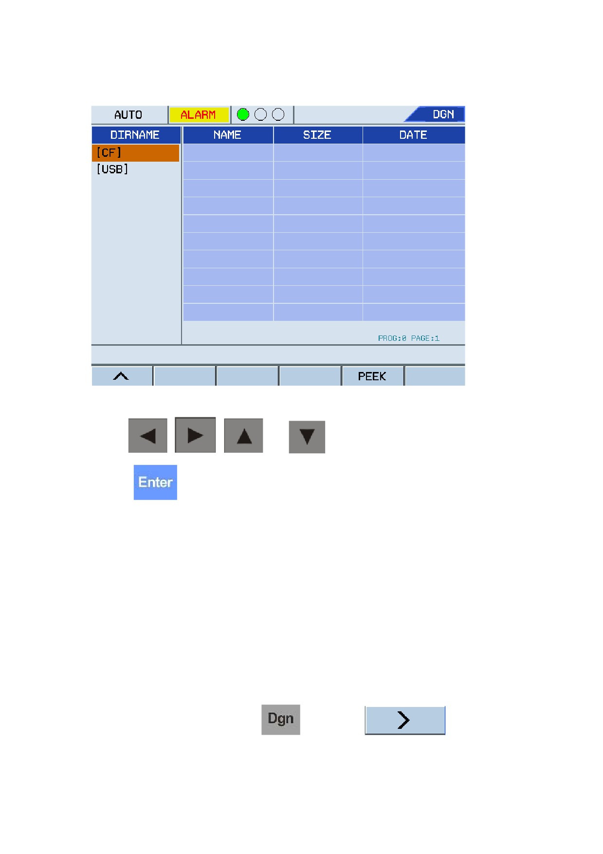
to select the file for update. See the figure below:
36
Operation Modes and Display Screen
Figure 1.29 Select update file
Use the
,
,
and
keys to select required directory and files,
press the
key to confirm the selection. The system then starts the update. After the
update, the system will automatically restart.
Note: Do not power off during the update, otherwise the system cannot start.
• SINGLE update
SINGLE update intends to independently update the upper-layer software, lower-layer software,
PLC, parameters, and fixed circular files with a single file. This is very convenient for users to
update the software, and thereby avoiding the efforts on update package development. SINGLE
update is generally used for update after critical errors are fixed or users modify PLC or
parameters.
To perform SINGLE update, press the
key, select F6
, press F3
37
Operation Modes and Display Screen
, use the
and
keys to select SINGLE, and then press the
and
keys to select a single file to update. Press the
key and select
the checkbox in front of the file, and then press F5
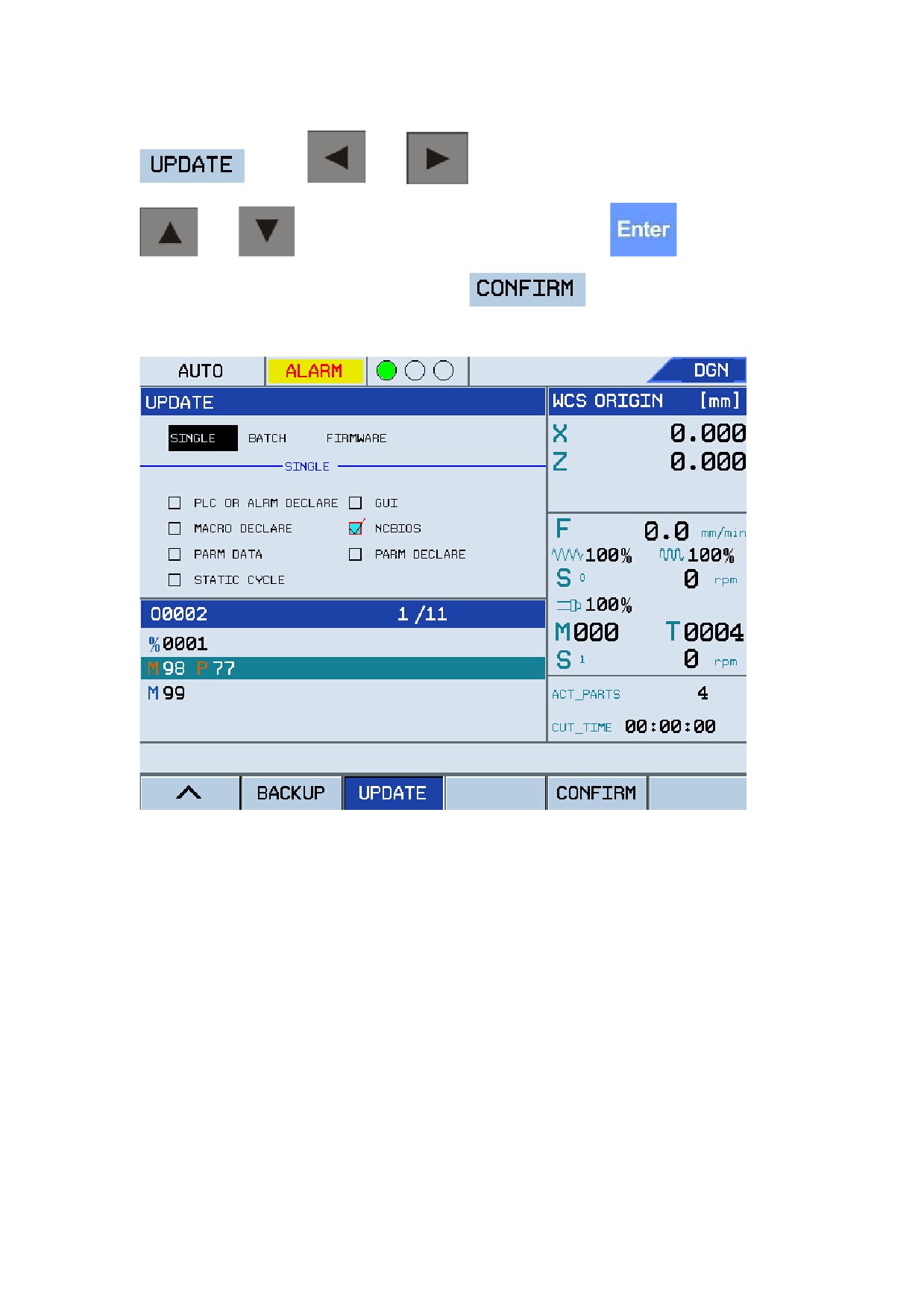
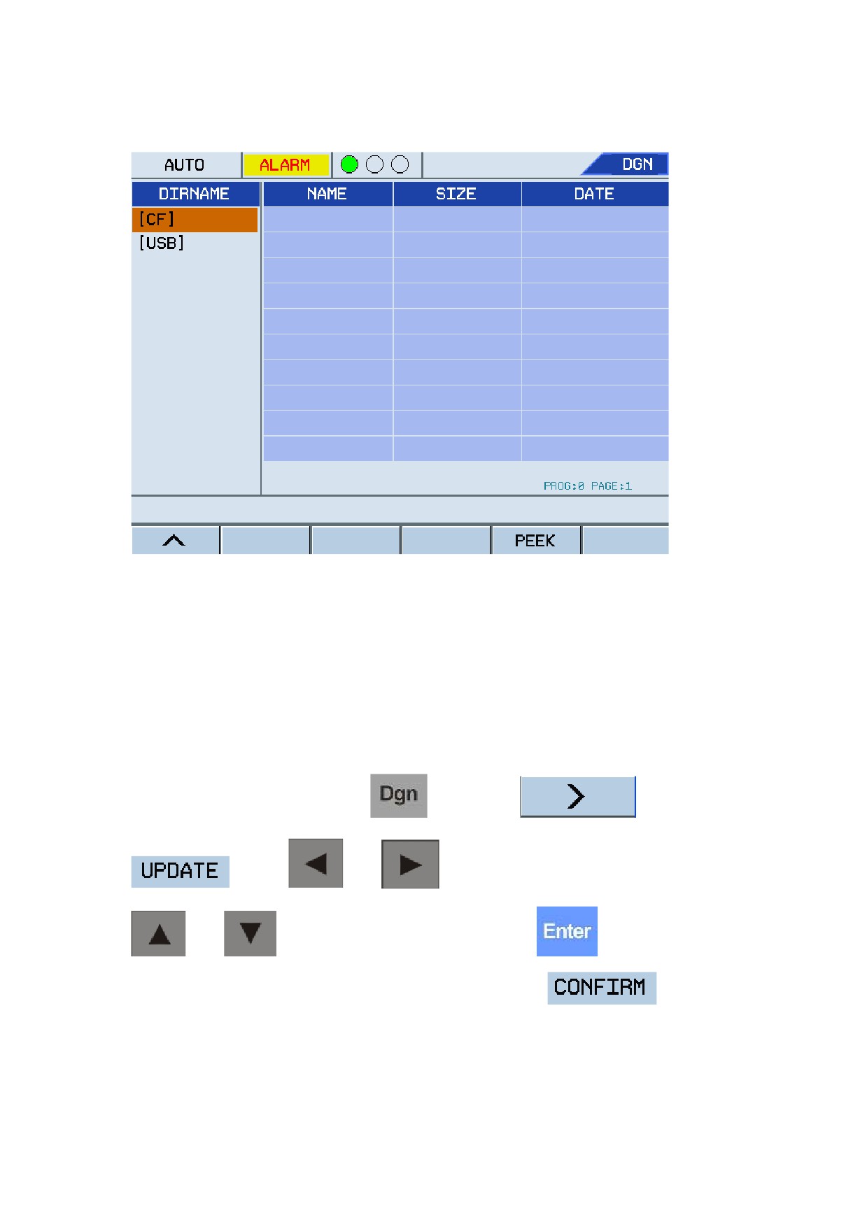
. See the figure below:
Figure 1.30 SINGLE update
38
Operation Modes and Display Screen
Figure 1.31 Select an update file
Note: Do not power off during the update, otherwise the system cannot start.
• BATCH update
BATCH update intends to update PLC, parameters, G code and tool compensation, which is
convenient for users to commission machines of the same type in batches. (This is generally used
for the update of batch commissioning.)
To perform BATCH update, press the
key, select F6
, press F3
, use the
and
keys to select BATCH, and then press the
and
keys to select files to upgrade. Press the
key to confirm the
selection, select the checkbox in front of the files, and then press F5
. The system
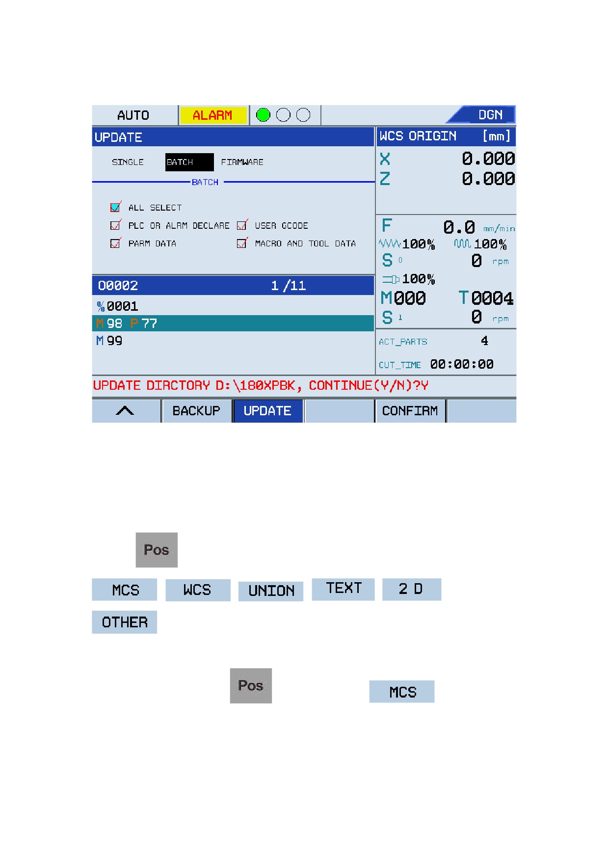
will prompt users the information about the batch file update directory. See the figure below:
39
Operation Modes and Display Screen
Figure 1.32 Batch file update
Note: The files for batch-file update is saved in the 180XPBK folder in the USB flash disk by
default. Do not power off during update, otherwise the system cannot start.
1.3.6 Position
Press the
key to enter the position screen, which consist of six submenus:
,
,
,
,
and
. You may press keys from F1 to F6 to enter corresponding submenus as required.
1.
Machine Coordinate System (MCS)
During program running, press
, and then press the F1
key to check the
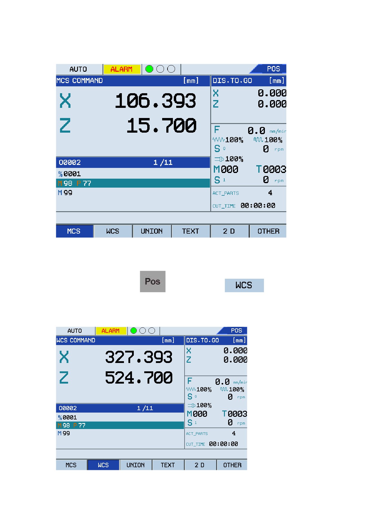
position of the current tool in the machine coordinate system. See the figure below:
40
Operation Modes and Display Screen
Figure 1.33 Command values in the MCS
2.
Workpiece Coordinate System (WCS)
During program running, press
, and then press the F2
key to check the
position of the current tool in the workpiece coordinate system. See the figure below:
Figure 1.34 Command values in the WCS
41
Operation Modes and Display Screen
3.
Union
During program running, press
, and then press the F3
key to check the
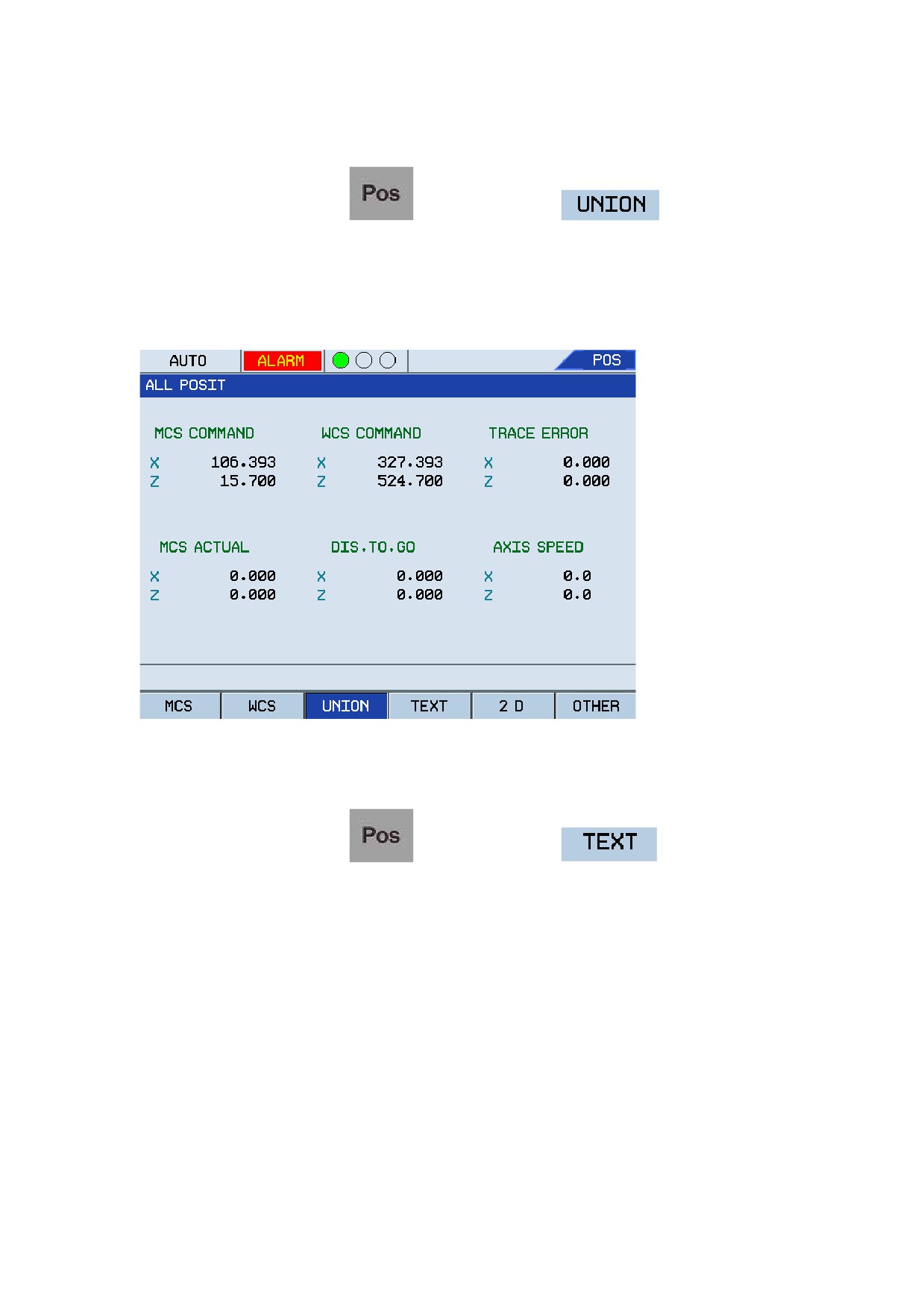
position of the current tool and "DIS. TO. GO." in the machine, workpiece, and relative coordinate
systems. See the figure below:
Figure 1.35 Axis values in multiple coordinate systems
4.
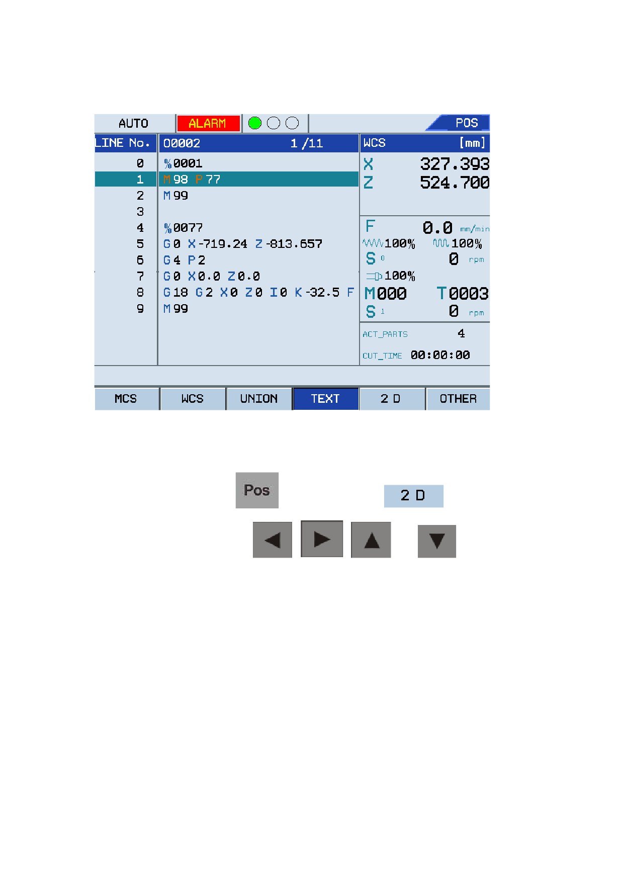
TEXT
During program running, press
, and then press the F4
key to check the
G code, workpiece command, Line No., M command, Feed rate, etc. See the figure below:
42
Operation Modes and Display Screen
Figure 1.36 Text display mode
5.
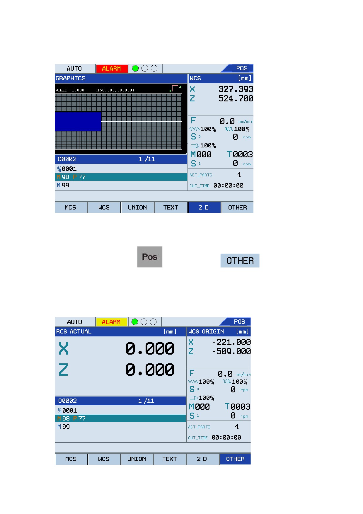
2D (Graph)
During program running, press
, and then press the F5
key to check the
real-time processing route. Use the
,
,
, and
keys to change
the display graph of the sample workpiece. See the figure below:
43
Operation Modes and Display Screen
Figure 1.37 Graph display mode
6.
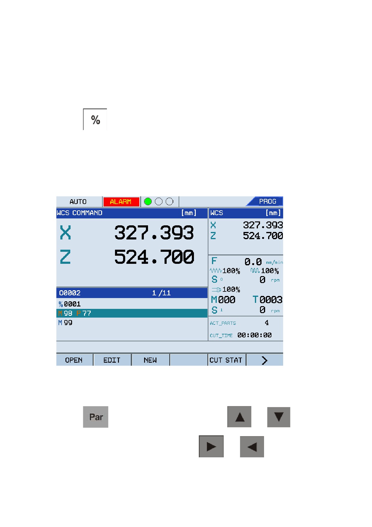
OTHER
During program running, press
, and then press the F3
key to check the
position of the current tool and the distance to go in the machine, workpiece, and relative
coordinate systems. See the figure below:
Figure 1.38 Other information
44
Operation Modes and Display Screen
Auxiliary Content
The auxiliary content are displayed in the upper-right corner. By default, the information about
"DIS. TO. GO." is displayed. The content in this area depends on the current menu, and can be
switched by pressing relevant keys.
Press the
key to change the auxiliary content displayed in the right corner. You may
switch between DIS. TO. GO, WCS COMMAND, WCS ORIGIN, and MCS ACTUAL. The
figure below shows that the auxiliary content has changed from DIS. TO. GO to WCS
COMMAND.
Figure 1.39 Switch auxiliary content
1.3.7 Parameters
Press the
key to enter the parameters screen. Use the
and
keys to
select the parameter type on the left, and then use the
and
keys to switch
between parameter type and parameter value.
45
Operation Modes and Display Screen
1.
Edit parameters
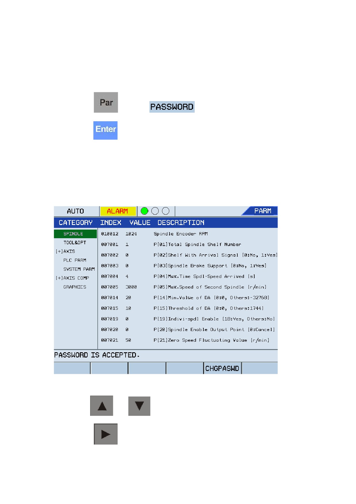
You need to enter the password for editing parameters to avoid random system parameter
modification, which may cause damage. Follow the instructions below to edit parameters:
a.
Press the
key and F1
, enter the required password, and then
press the
key for confirmation.
y
If the password is correct, the message "PASSWORD IS ACCEPTED" as shown in the
figure below is displayed.
y
If the password is incorrect, you cannot modify the parameters.
Figure 1.40 Edit system parameters
b.
Use the
and
keys to select the parameter type to edit.
c.
Press the
key to select the parameter to edit.
46
Operation Modes and Display Screen
d.
Press the
key to enter the editing state, and then press the
key to clear
the previous value.
e.
Enter a new value, and press the
key for confirmation.
f.
Press the
or
key to edit other parameters.
g.
After editing all required parameters, press F4
to save the modified
information and repower on the system.
2.
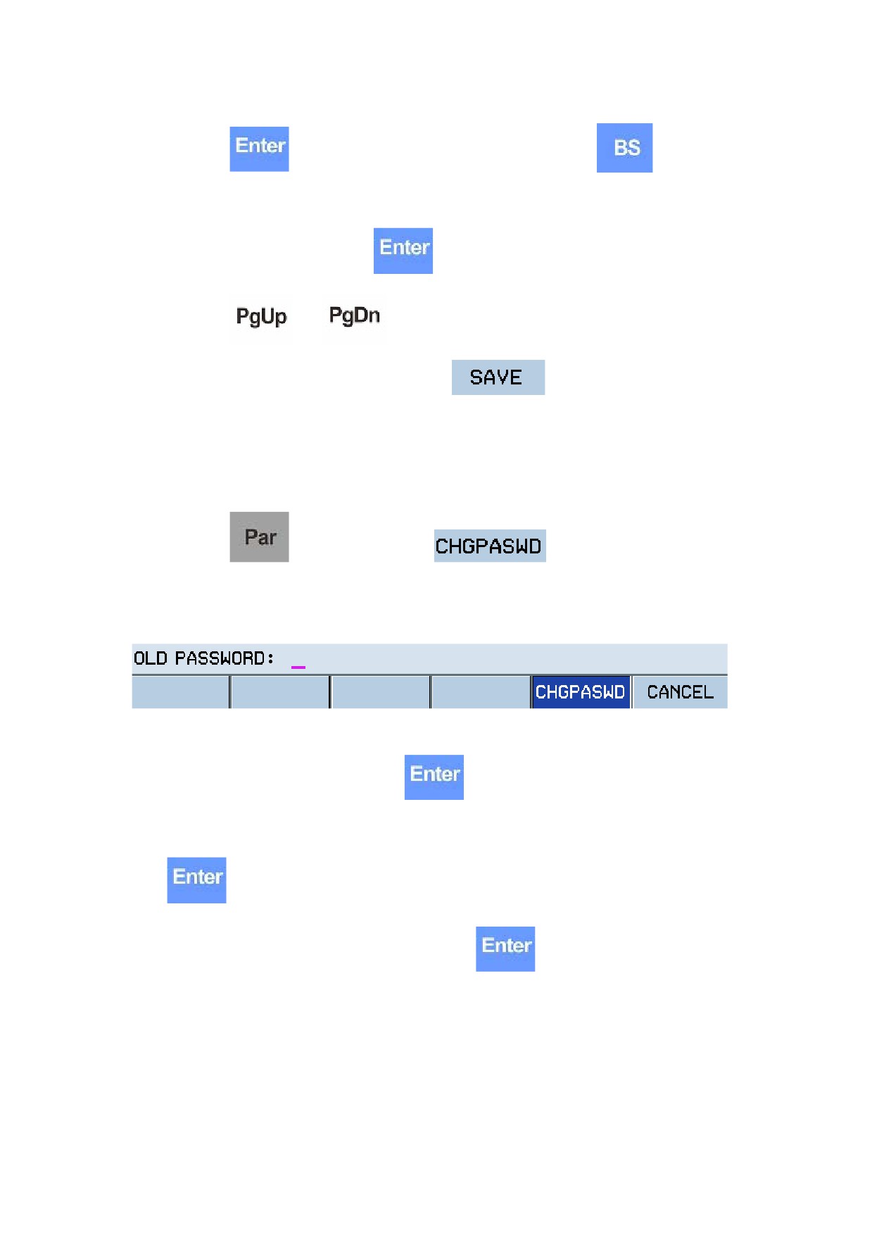
Change parameter editing password
Follow the instructions below to change the parameter editing password:
a.
Press the
key, and then press F5
The system prompts you to enter the old password. See the figure below:
Figure 1.41 Change parameter editing password
b.
Enter the old password, and press the
key for confirmation.
c.
If the password is correct, the system prompts you to enter a new password. Press the
key to confirm the new password.
d.
Enter the new password once again and press the
key for confirmation.
y
If the two new passwords entered are the same, then the password is changed
successfully.
y
If the new passwords you entered are different, the system prompts you that the new
passwords are not the same and the password modification failed.
47
Power on/off and Safety Protection
2 Power on/off and Safety Protection
This section describes the operations on power on/off, emergency stop, reset, reference home,
hardware and software limits, Over-travel protection, etc.
2.1 Power on
Follow the instructions below to power on the machine:
1.
Check and make sure the machine is normal to run.
2.
Make sure the power supply and voltage to meet requirements and the wiring is correct and
tight.
3.
Power on the machine (for more details, see the user manual of the machine).
4.
Power on the CNC system.
5. Make sure the indicators on the machine control panel are normal.
After powering on the CNC system, the system automatically runs system software and enter the
Programming main menu.
Figure 1.2 shows the software operation interface after power on, and the operation mode is Auto.
2.2 Power off
Follow the instructions below before power off:
1.
Make sure the X and Z axis of the CNC system is in the stop status.
2.
Auxiliary functions (such as main spindle, and pumps) are disabled.
3.
Cut off the power for the servo motor, then for the CNC system, and lastly for the machine.
2.3 Home to Reference Point
The machine coordinate system is the precondition of machine operation. Therefore, homing to
the reference point is required before powering on or resetting the machine. Follow the
instructions below:
1.
Switch the mode to the Reference mode by pressing the Reference key on the control panel.
2.
Press "+X" or "+Z" to move the machine along with the selected axis. After both axis
homering to the reference point, the machine coordinate system is established.
Note:
1.
After power on, each axis must be homed to the reference point, and then other operations
48

Power on/off and Safety Protection
can be performed. If the floating origin function has been enabled, the operation of homing
is not required. For more details, see section 1.3.2.
2.
Press "+X" and "+Z" simultaneously to home both X axis and Z axis to the reference point at
the same time.
3.
After homing each axis to the reference point, you do not need to home the axis to the
reference point during operation unless a servo driver alarm is reported.
2.4 Over-Travel Protection
2.4.1 Hardware Over-Travel Protection
Each axis has a hardware limit and a software limit at each end of the axis. If a hardware switch is
encountered on an axis, the hardware over travel occurs (the running status displayed on the
screen is "Emergency stop" with the indicator blinking continuously), and the system will perform
emergency stop accordingly based on the actual situation.
The tool can be retrieved from an over-travel status by following the operations below:
1.
If no over-travel release key is available, press the
key to reset the system.
2.
If an over-travel release key is available, press the over-travel release key, and then press the
key until the system is reset.
3.
In the Manual mode, move the tool backward on the axis to be out of over-travel.
4.
Release the over-travel release key.
If the running status displayed on the screen changes from "Emergency stop" to "Normal", the
system restores and may proceed with operations.
Note: Please pay attention to the motion direction and speed when moving the tool out of
over-travel to avoid tool collision with the machine.
2.4.2 Software Over-Travel Protection
Positive and negative software limits are defined for each axis using feed parameters, which takes
effect after homing to reference point. When the axis is commanded to go beyond these limits
(over-travel), the software switch will be encountered, corresponding alarms will be reported, and
49

Power on/off and Safety Protection
the motion ceases and no further motion in this direction is permitted. To clear the alarm, press the
key, and move the tool backward on the axis.
2.5 Emergency Operation
2.5.1 Reset
If a CNC system error or axis error occurs, you may press the Reset key to reset the system. In this
way, all axis stop motion and all auxiliary functions unavailable; the machine stops running, and
the system is in the initiation status; All system alarms are cleared, and the processing program is
reset.
2.5.2 Emergency Stop
During machine operation, you may press the
key in case of emergency. Once the
Emergency Stop button is pressed, the system enters into the "Emergency Stop" mode, and the
servo and spindle are disabled (the feed driver power supply is cut off in the control cabinet).
Release the Emergency Stop button or twist the ES button clock-wise, then the system enter the
reset status.
Make sure that the trouble has been solved before releasing the Emergency Stop button, and home
the axis to the reference point again after releasing the Emergency Stop button to ensure correct
coordinate position (if the machine origin point has not been set, you need to set the floating origin
point).
For information about circuit connection, see HNC-180 Series Installation and Connation Guide.
Note: Press the Emergency Stop button before turning the power on or off to avoid device
crash.
2.5.3 Feed Hold
The "Feed Hold" button is used to pause the ongoing machining operation. This operation cannot
stop the machine immediately during thread cutting and cycle command running.
2.5.4 Power off
During machine operation, you may cut the power supply off in case of emergency to avoid
50
Power on/off and Safety Protection
accidents. However, the coordinate position displayed after re-powering on may be different from
the actual position, and therefore you need to perform tool settings again.
51
Manual Operation
3 Manual Operation
3.1.1 Manual Feed
Press the
key (the indicator is lit) to enter the Manual mode. In this mode, you may
move the cutting tool along a motion axis with jog feed. The following information describes the
motion along the X axis:
1.
Press the "+X" or "-X" key (the corresponding indicator is lit) to move the X axis
continuously in the positive of negative direction.
2.
Release the "+X" or "-X" key (the corresponding indicator is off) to decrease and stop the
motion along the X axis.
Perform similar operation to move the Z axis continuously in the positive or negative direction. In
the Manual mode, press the X and Z axis keys simultaneously to manually control the X and Z
axis motion at the same time.
3.1.2 Rapid Traverse Feed Rate
In the manual feed mode, press the
key to move the tool rapidly in the positive or
negative direction on relevant axis.
3.1.3 Manual Feed Rate Adjustment
Use the
button to adjust the feed rate with the manual feed "override ratio",
which is between 0% to 120%.
The default spindle feed rate after power on is 100%. Press the minus "-" key to decrease the feed
rate by 10%. The minimum value is 10%. Press the plus "+" key to increases the feed rate by 10%.
The maximum value is 150%.
The default rapid traverse federate after power on is 20%. Press the minus "-" key to decrease the
feed rate by 10%. The minimum value is 10%. Press the plus "+" key to increases the feed rate by
52
Manual Operation
10%. The maximum value is 100%.
3.1.4 Hand-wheel Feed
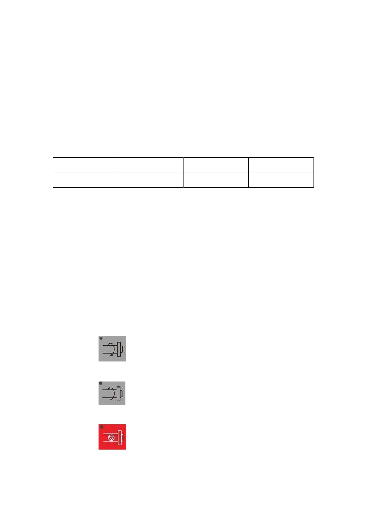
Press the Hand wheel key (the indicator is lit) to enter the hand wheel mode. Rotate the feed rate
adjustment button to set the feed rate for the cutting tool. Clockwise rotation moves the selected
axis in the positive axis direction. Counter-clockwise rotation moves the selected axis in the
negative axis direction. The table below describes the relationship between the increment of hand
wheel motion and the amount of magnification (X1, X10, X100).
Magnification
x 1
x 10
x 100
Increment (mm)
0.001
0.01
0.1
The rotation direction determines the feed direction. Generally, Clockwise rotation moves the
selected axis in the positive direction. Counter-clockwise rotation moves the selected axis in the
negative direction. If the feed rate direction is opposite to this, you may switch the A and B signals
on the hand wheel.
3.2 Other Manual Operation
3.2.1 Clockwise and Counter Clockwise Rotation of
Spindle
In the manual mode, if the machine is powered on for the first time, follow the instructions below:
1.
Press the
key to rotate the spindle in the clockwise direction at the specified
speed. The LED indicator is lit.
2.
Press the
key to rotate the spindle in the counter-clockwise direction at the
specified speed. The LED indicator is lit.
3.
Press the
key to stop the spindle manually. The LED indicator is lit.
If you manually rotate the spindle after auto running, the spindle rotation speed will maintain that
in the auto running.
53

Manual Operation
Note: If you press one of the
,
, and
keys (the indicator is lit),
the other keys will be invalid (the indicators turn off).
3.2.2 Spindle Jog
In the manual mode, press and hold the Spindle Jog key (the indicator is lit), the spindle will rotate
at the speed specifying by machine parameters. Release the key (the indicator turns off)d, the
spindle will stop running.
3.2.3 Coolant Control
In the Manual mode, press this key to start or stop the coolant flow. Coolant function is enabled if
the LED light is lit and disabled if the LED light is off.
3.2.4 Lubrication Control
1.
Manual-Lubrication
In the manual operation mode, press this key to enable or disable the lubrication function.
2.
Auto-Lubrication
You may define the lubrication duration by specifying PLC parameters 007054 and 007055. The
system will start lubrication for a period specified by 007055 after power on, and then stop
lubrication for a period specified by 007054. This procedure will be repeated.
3.2.5 Turret Rotation
In the manual mode, press the
key to rotate the turret to the next tool number in the
clockwise direction. The number of the tool where the turret will rotate to depends on the times
you press the key. For example, if the current tool number is 1, and you may continuously press
the key for three times to rotate the turret to the fourth tool.
54
Automatic Operation
4 Automatic Operation
4.1 Auto-Operation
This section describes the operation related to automatic operation.
4.1.1 Enable Auto-Operation
After a program file is loaded and verified, you may enable the auto operation function.
1.
Press the
key (the indicator is lit) on the operation panel to enter the auto
operation mode.
2.
Press the
key (the indicator is lit) on the operation panel to automatically run the
loaded program.
4.1.2 Pause Auto-Operation
During program operation, you may follow one of the methods below to pause the on-going
operation:
1.
During program operation, press the
key (the indicator is lit) to enter the Feed
Hold mode and pause the on-going operation, and then press the
key to proceed
with the auto operation.
2.
Use the M00 command to pause the on-going auto operation, and then press the
key to proceed with the auto operation.
3.
Use the G04 command to pause the on-going auto operation. The pause duration is specified
by the G04 parameter. Press the
key to proceed with the operation.
4.1.3 Stop the Auto-Operation
During auto operation, you may follow one of the methods below to stop the auto operation:
1.
Press the
key to stop the operation of all axis. In this case, the M code and S code
55
Automatic Operation
functions are unavailable, and the system terminates the auto operation, G code function and
status maintaining function.
2.
Press the
key to stop the operation in case of emergency (only when the external
ES signal is valid). In this case, the CNC system enters the Emergency Stop mode, the
motion is stopped, and all other operations such as spindle rotation and coolant flow are
stopped. Release the key to clear the alarm and enter the Reset mode.
3.
Press the
key, press the F2
key, and then press the F4
key. The system prompts you whether to stop the program. Press Y or press
the Enter key to stop the program.
4.2 Start from a Radom Line
When the auto operation is paused, the program can be restarted from the location where it is
paused or from a random line. Press the
key, select a program, press F6
under
, and then press F2
to start the operation
as required.
4.2.1 Start from the Red Line
Follow the instructions below to restart the operation from the red line
1.
Press the
key to enter the feed hold mode (the indicator is lit).
2.
Use the
and
keys to move the blue bar to the desired start line, and at this
time the blue bar turn red.
3.
Press F2
, and select the row from which to start the operation (the red bar
turn blue).
4.
Press the
key to start the operation from the blue bar (that is, the red line).
56
Automatic Operation
4.2.2 Start from the Specified Line
Follow the instructions below to start the operation from the specified line:
1.
Press the Feed Hold key on the operation panel to enter the feed hold mode (the indicator is
lit).
2.
Press F3
. The system prompts you to enter the line number from which the
operation starts.
3.
Enter the line number and press the
key to confirm.
4.
Press the
key to start the operation from the specified line.
4.3 Single Block Operation
Press the
key to enter the Single Block mode. The program will be executed block by
block.
1.
Press the
key to execute a block of the program, and then the motion speed on the
axis will decrease to stop, and the tool stops.
2.
Press the
key again to execute the next block of the program, and after the
execution is completed, the operation will stop.
4.4 Over-Block Operation
If you need neither to execute a block of program nor to delete it, you may enable the over-block
operation function. Press the
key on the operation panel, and the system will
automatically skip the block of the program beginning with the "/" symbol. Release the key to
disable the over-block operation.
Note: If the over-block operation function is disabled, the system will not skip the program
beginning with the "/" symbol.
57
Automatic Operation
4.5 Breakpoint Related Operation
During processing, there are always some large workpieces which requires complicated operation
and long duration. It is necessary to save and restore the breakpoint for further processing. In other
words, you may save the breakpoint (let the system remember various status of the time point) and
cut the power supply. After a period of time, you may turn on the power supply and restore the
breakpoint (let the system restore the status when the processing is broken) to proceed with the
processing from the breakpoint.
4.5.1 Save the Breakpoint
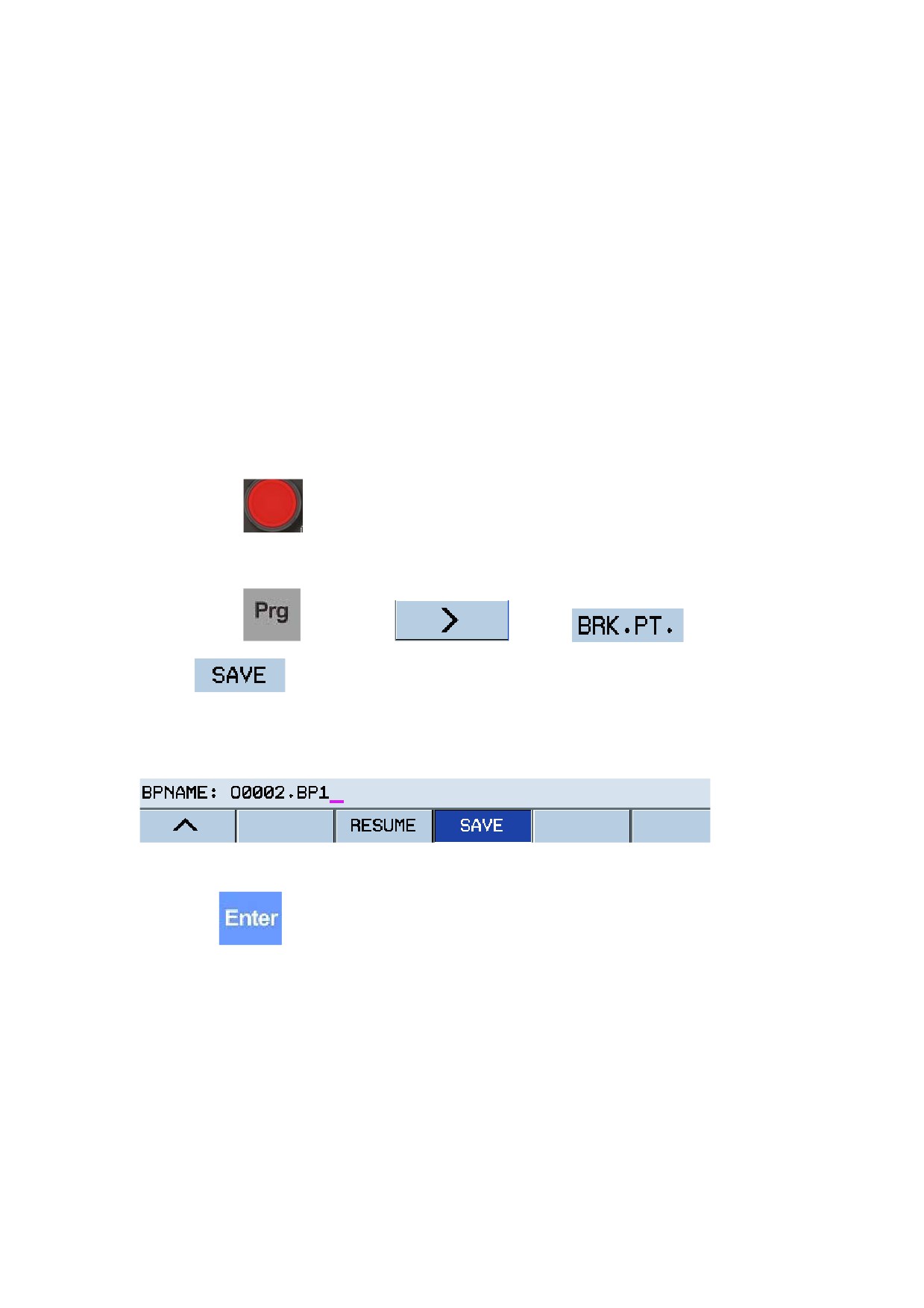
Follow the instructions below to save the breakpoint:
1.
Press the
key to enter the feed hold mode (the indicator is lit). This operation can
be performed only when the program is in the Auto operation mode.
2.
Press the
key. Press F6
, press F6
, and then press
F4
. The system will prompt you to enter the file name for the breakpoint. See
the figure below:
Figure 4.1 Save breakpoint file
3.
Press
, and the system will prompt you to select a storage path with "Save to: 1 CF
card; 2 USB; 3 Cancel". You may select 1 or 2 as required. The system will automatically
create a file named with the current program name and suffixed with BP1 in the root
directory of the selected storage card. You may modify the name without a suffix.
Note: It's not allowed to save breakpoint during program running.
4.5.2 Resume Breakpoint
Follow the instructions below to resume a breakpoint:
58
Automatic Operation
1.
If the power is off after you save the breakpoint, you need to home the tool back to the
reference point after power on. Otherwise, skip this step to step 2.
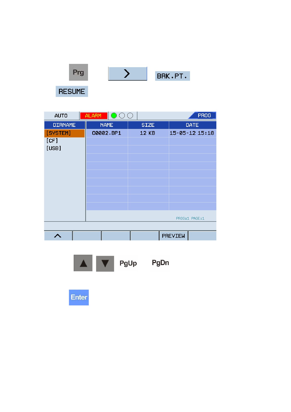
2.
Press
, press F6
, F6
, and then press
. The system displays all saved breakpoint files. See the figure below:
Figure 4.2 Select a breakpoint file to resume
3.
Use the
,
,
and
keys to select a breakpoint file to
resume as required.
4.
Press
. The system will resume the breakpoint of the program based on the
information saved in the breakpoint file. In this way, you may back to the breakpoint in the
MDI mode. You may press the F5 key to delete the breakpoint file.
4.5.3 Return to Breakpoint
After saving the breakpoint, you may proceed with the program through breakpoint location if no
axis motion has been performed. Follow the instructions below:
59
Automatic Operation
1.
Resume the breakpoint based on the instruction in section 4.5.2.
2.
Move the cutting tool near to the break point, and make sure no collision during this
operation.
3.
Under the MDI main menu, press F4
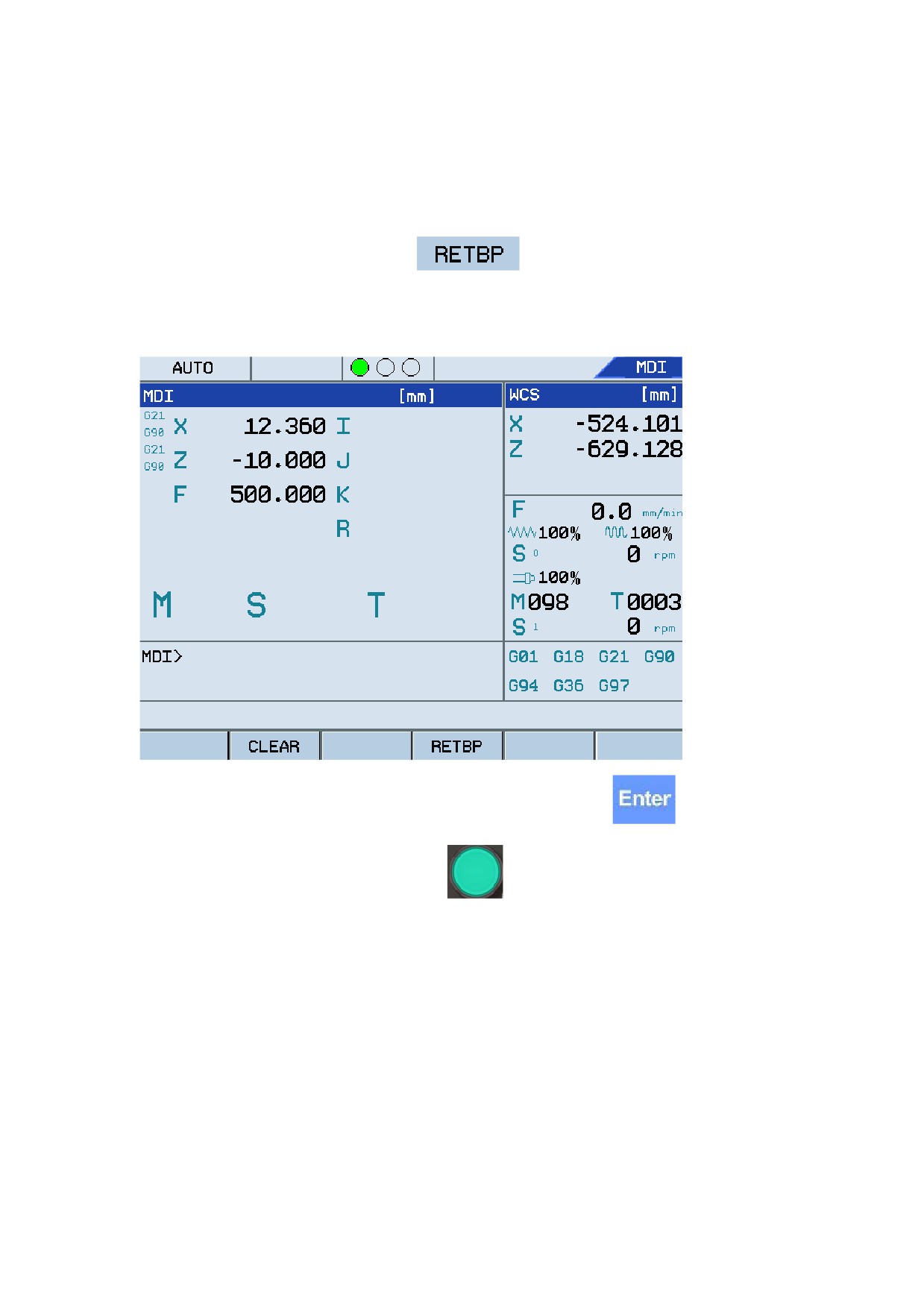
. The system automatically inputs the
breakpoint information into the MDI program segment. See the figure below:
Figure 4.3 Return to breakpoint
4.
You may also manually enter the data information, and then press
5.
In the Single Block or Auto mode, press
to run the program from the breakpoint.
4.6 Operation During Program Running
4.6.1 Adjust Feed Speed
In the Auto or Single Block mode, you may adjust the feed speed by using the override keys if the
feed rate of the F-code programming is too high or too low. The adjustment range is 0% to
120%.
4.6.2 Adjust Rapid Traverse Speed
In the Auto or Single Block mode, you may press the rapid traverse adjustment button to adjust the
60

Automatic Operation
rapid traverse speed. Pressing the minus "-" key reduces the feed rate by 10% of the 100%
rapid traverse speed. Pressing the minus "+" key increases the feed rate by 10% of the 100% rapid
traverse speed. The range of adjustment is 0 to 100%.
4.6.3 Adjust Spindle Speed
In the Auto or Single Block mode, you may adjust the spindle speed by using the three override
keys if the federate of the S-code programming is too high or low (except for the tapping
command).
Press
(the indicator is lit) and the spindle speed is set to the full value (100%). Press
to increase the speed by 10%. Press
to decrease the speed by 10%.
The adjustment range is 10%-150%.
Do not adjust the spindle speed during mechanical gear rate switching.
61
Program Editing and Management
5 Program Editing and Management
This section describes the program-related operation under the
menu, such as selecting
a program, editing a program, verifying a program, and rerunning a program.
5.1 Select a Program
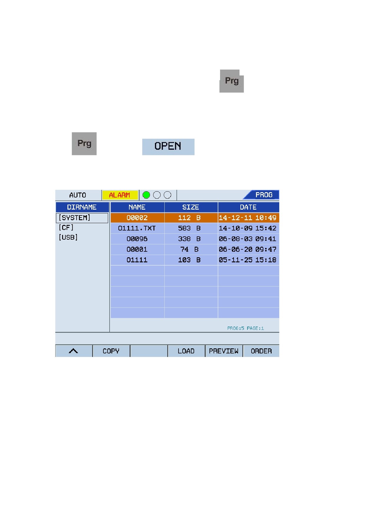
Press
, and press the F1
submenu. The system displays the
programs in each storage card. See the figure below:
Figure 5.1 Select a program file in a storage card
5.1.1 Select a Program
You can select a program from the storage cards as required.
1.
System disk: G-code programs in the built-in system flash disk.
2.
USB: G-code programs in the USB flash disk.
If you select no program, the system displays the program saved in the buffer zone previously.
62
Program Editing and Management
Press
and
to switch between the program storage card (displays only the
programs in the root directory) and corresponding program list screens. Press
,
,
and
keys to select programs to be run, and press
or F4
to confirm and add the selected programs. In the Auto or Single Block mode,
press
to run the program. If an error occurs, the message "ALARM" will be displayed
and the indicator will blink continuously. You may press
to check detailed alarm
information.
5.1.2 Preview Programs
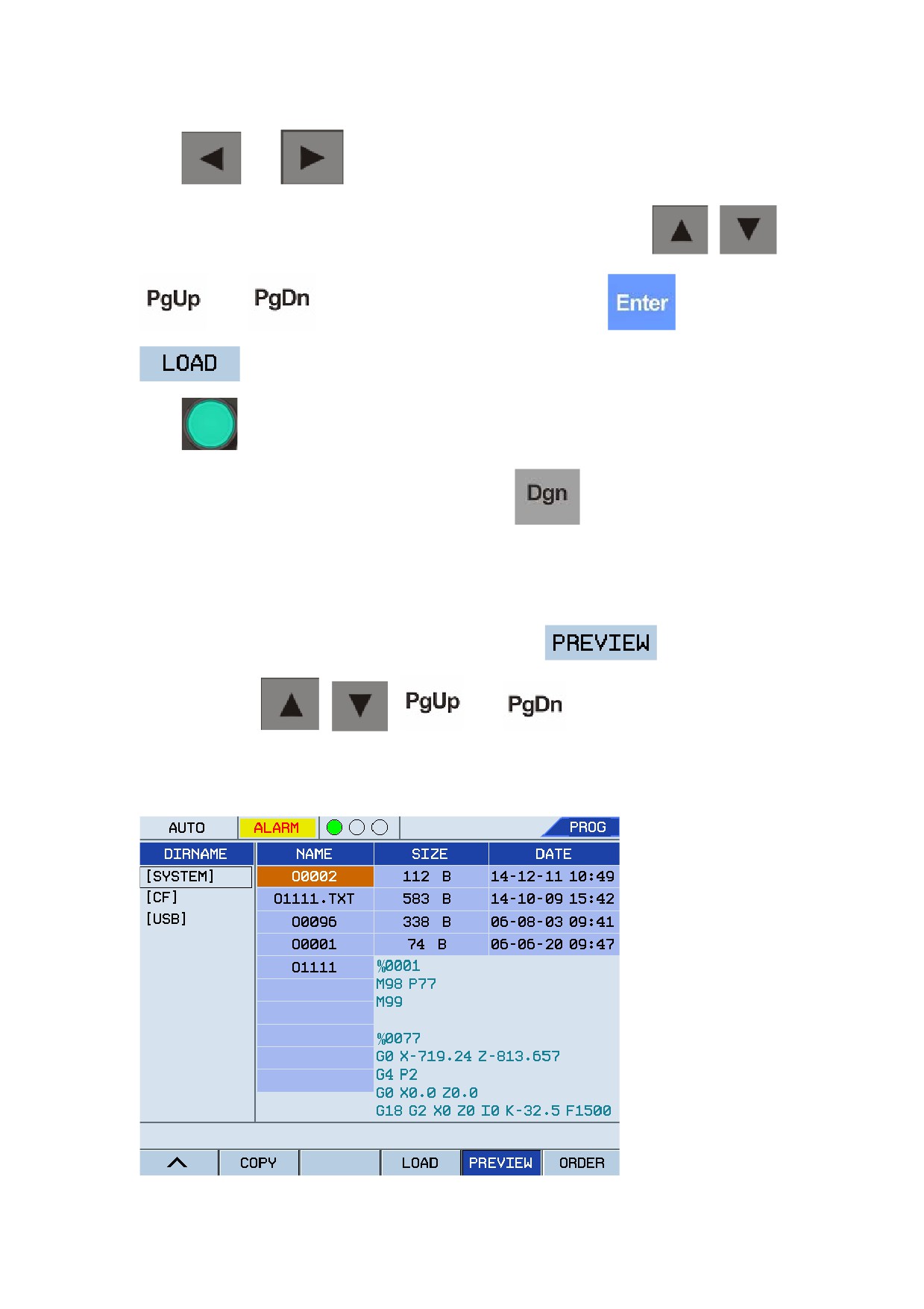
When the cursor is placed over the selected program, press F5
to preview the
program. Use the
,
,
, and
keys to preview other programs
as required. See the figure below:
Figure 5.2 Pre-view a selected program
63
Program Editing and Management
5.2 Edit a Program
5.2.1 Edit a program
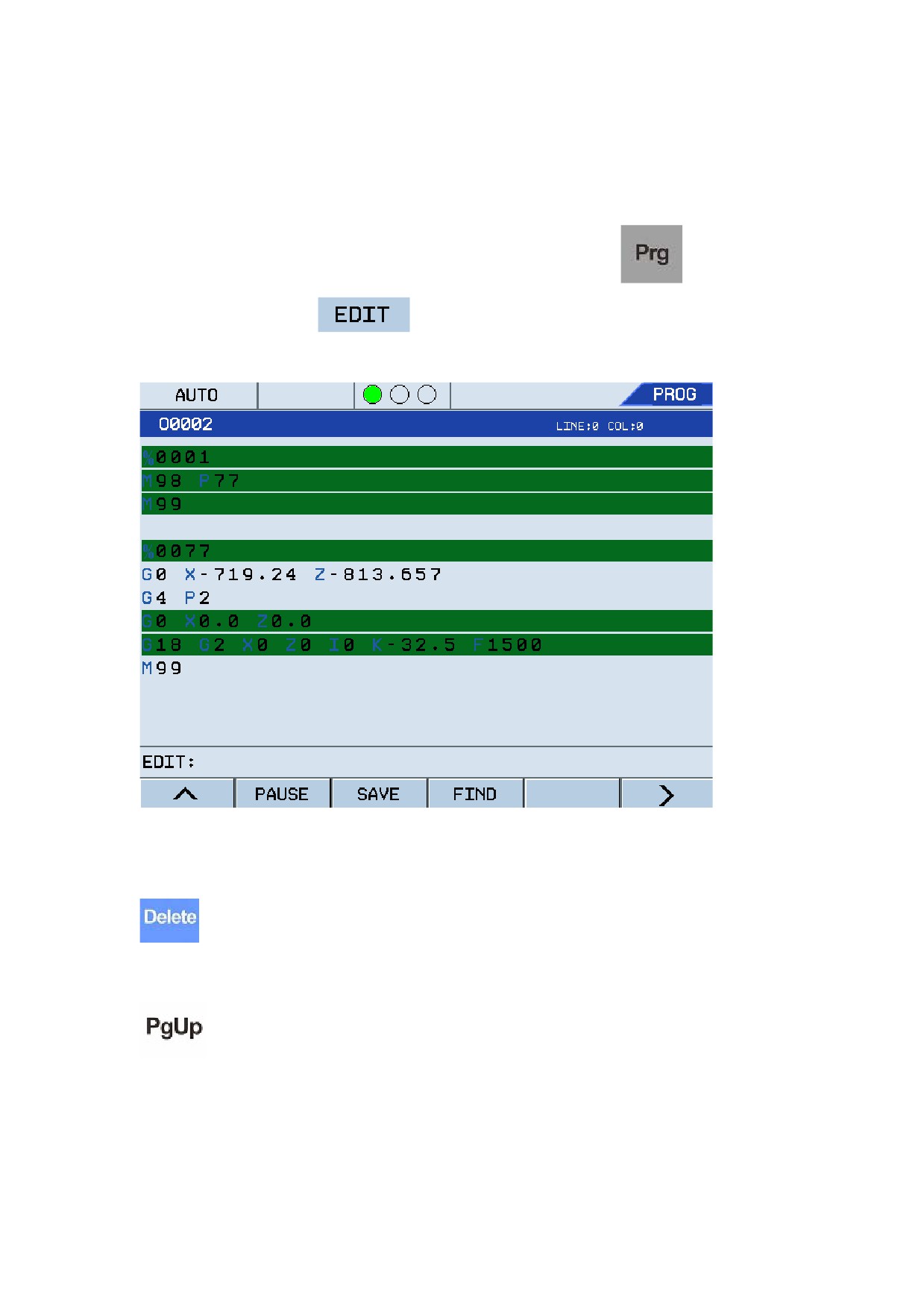
If a program error occurs or a program is required to edit, you may press
to select the
program, and then press F2
to edit it as required. See the figure below:
Figure 5.3 Edit a selected program
The following shortcut keys are used to edit a program:
: Delete the character right to the cursor and maintain the cursor position. The remaining
characters right to the cursor will shift leftwards accordingly with one-character space.
: Move the program to be edited one screen up to the program header and maintain the
cursor position. If it has reached the program header, the cursor will move to the first character in
the first row of the program.
64
Program Editing and Management
: Move the program to be edited one screen down to the program end and remain the
cursor position. If it has reached the program end, the cursor will move to the first character in the
last row of the program.
: Delete the character left to the cursor and the cursor will shift leftwards with
one-character space. The remaining characters right to the cursor will shift leftwards accordingly
with one-character space.
: The cursor shifts leftwards with one-character space.
: The cursor shifts rightwards with one-character space.
: The cursor shifts one row upwards.
: The cursor shifts one row downwards.
Note: The program block displayed in the dark color tone cannot be directly edited. You need to
press F4
, and then press Y or
after the message "Exit the current
running Y/N? (Y)" is displayed. After that, you may edit the program.
5.2.2 Save a Program
To save an edited program or a created program, press the F3
. The system
automatically saves the program with the previous program name.
If the system failed to save the edited program, a corresponding failure message will be displayed.
In this case, the program is a read-only file and cannot be saved with modification, but you may
save it as another file. If the failure is caused of insufficient storage space, you may delete
unnecessary files and resave the program.
5.2.3 Search Information
To search specific content (numbers or characters) within a program, press F4"Search", and the
65