HNC-180xpT3. Operation Guide (V 2.0 2015.4) - page 1
Contents
Contents
1
Operation Modes and Display Screen
1
1.1
Overall Layout
1
1.1.1 Manual Data Input Keys
1
1.1.2 Main Menus
3
1.1.3 Machine Operation Keys
5
1.1.4 Operation Interface
9
1.2
Overview of Operation Modes
10
1.3
Display Screen
10
1.3.1 Program
11
1.3.2 Set
16
1.3.3 MDI
23
1.3.4 Offset
25
1.3.5 Tool Diagnosis
30
1.3.6 Position
40
1.3.7 Parameters
45
2
Power on/off and Safety Protection
48
2.1
Power on
48
2.2
Power off
48
2.3
Home to Reference Point
48
2.4
Over-Travel Protection
49
2.4.1 Hardware Over-Travel Protection
49
2.4.2 Software Over-Travel Protection
49
2.5
Emergency Operation
50
2.5.1 Reset
50
2.5.2 Emergency Stop
50
2.5.3 Feed Hold
50
2.5.4 Power off
50
Contents
3
Manual Operation
52
3.1.1 Manual Feed
52
3.1.2 Rapid Traverse Feed Rate
52
3.1.3 Manual Feed Rate Adjustment
52
3.1.4 Hand-wheel Feed
53
3.2
Other Manual Operation
53
3.2.1 Clockwise and Counter Clockwise Rotation of Spindle
53
3.2.2 Spindle Jog
54
3.2.3 Coolant Control
54
3.2.4 Lubrication Control
54
3.2.5 Turret Rotation
54
4
Automatic Operation
55
4.1
Auto-Operation
55
4.1.1 Enable Auto-Operation
55
4.1.2 Pause Auto-Operation
55
4.1.3 Stop the Auto-Operation
55
4.2
Start from a Radom Line
56
4.2.1 Start from the Red Line
56
4.2.2 Start from the Specified Line
57
4.3
Single Block Operation
57
4.4
Over-Block Operation
57
4.5
Breakpoint Related Operation
58
4.5.1 Save the Breakpoint
58
4.5.2 Resume Breakpoint
58
4.5.3 Return to Breakpoint
59
4.6
Operation During Program Running
60
4.6.1 Adjust Feed Speed
60
4.6.2 Adjust Rapid Traverse Speed
60
4.6.3 Adjust Spindle Speed
61
Contents
5
Program Editing and Management
62
5.1
Select a Program
62
5.1.1 Select a Program
62
5.1.2 Preview Programs
63
5.2
Edit a Program
64
5.2.1 Edit a program
64
5.2.2 Save a Program
65
5.2.3 Search Information
65
5.2.4 Locate a Line
66
5.2.5 Save as
66
5.2.6 Replace a String of Characters
66
5.2.7 Delete a Line
67
5.2.8 Edit a Block
67
5.3
Create a Program
67
5.4
Delete a Program
67
5.5
Copy a Program
68
5.6
Verify a Program
68
5.7
Restart a Program
70
6
User Operation and Maintenance Information
71
6.1
Environmental Requirements
71
6.2
Grounding
71
6.3
Power Conditions
72
6.4
Clean Fan Filter
72
6.5
Operations After Being Left Unused
72
7
Appendix 1 Parameter Settings
73
7.1
Overview
73
7.2
Check and Set Parameters
74
7.3
Detailed Parameter Description
75
7.3.1 Spindle Parameters
75
Contents
7.3.2 Tool & OPT
80
7.3.3 Feed Axis Parameters (X axis)
82
7.3.4 PLC Parameters
89
7.3.5 System Parameters
92
7.3.6 Axis Compensation (X-axis)
95
7.3.7 Graphics
99
Operation Modes and Display Screen
1 Operation Modes and Display Screen
1.1 Overall Layout
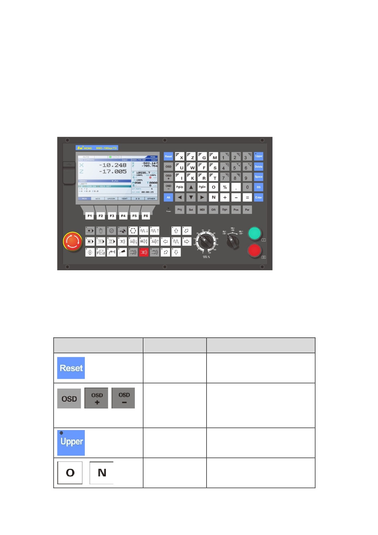
Century Star HNC turning system provides a standard and delicate operation panel, with compact
dimension: 420 x 260 x 100 mm (W x H x D). See the figure below:
Figure 1.1 Operation panel of HNC turning system
Based on functions, HNC turning system includes HNC-180xpT3 and HNC-808TEA numerical
controls.
1.1.1 Manual Data Input Keys
Key
Name
Description
Reset the system, stop feeding, clear
Rest
alarms, etc.
On-screen display
Modify the brightness of the screen.
keys (OSD+/OSD-)
Upper
Auxiliary function key.
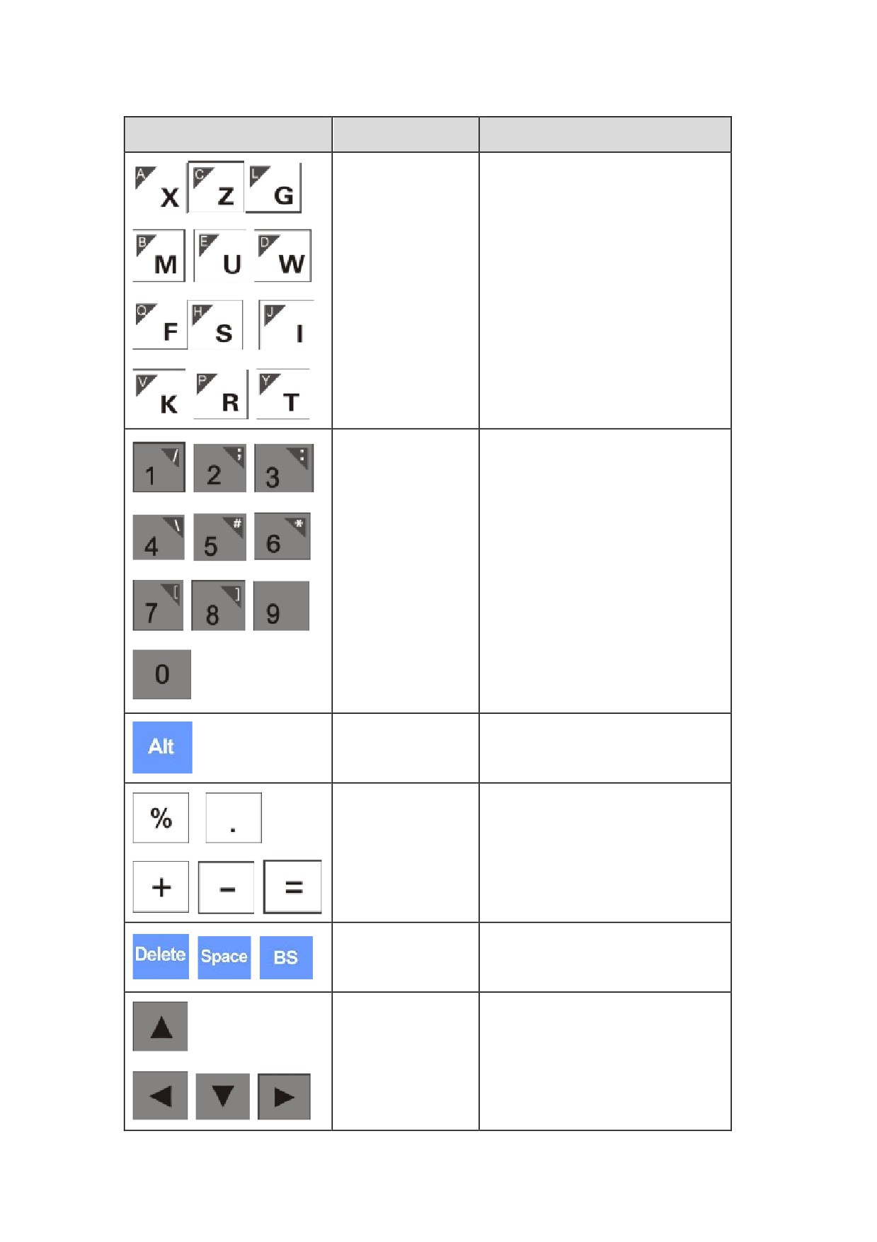
Character input keys
Input a single character.
1
Operation Modes and Display Screen
Key
Name
Description
Directly input characters.
Press the Upper key, and then press
the keys to input the characters in the
upper left corner.
Directly input numbers. Press the
Numbers/Symbols
Upper key, and then press the keys to
keys
input the symbols in the upper right
corner.
Alt
None
Input percentage, decimal point, plus,
Symbol keys
minus, and equal symbols.
Insert, modify, and delete information
Editing keys
for editing programs and fields.
Move the cursor to the required
Direction keys
direction.
2
Operation Modes and Display Screen
Key
Name
Description
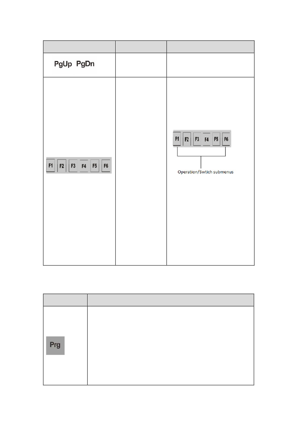
Page down and up
Under the same screen, move one
keys
page up or down as required.
After paging down or up, you can
press a soft key to display its
submenu and relevant information.
See the figure below:
Soft keys
Usage of soft keys:
1. Used to switch submenus on the
current screen
2. Used to perform operations on
the current submenu such as
editing and modifying data or
display information
1.1.2 Main Menus
Menu
Description
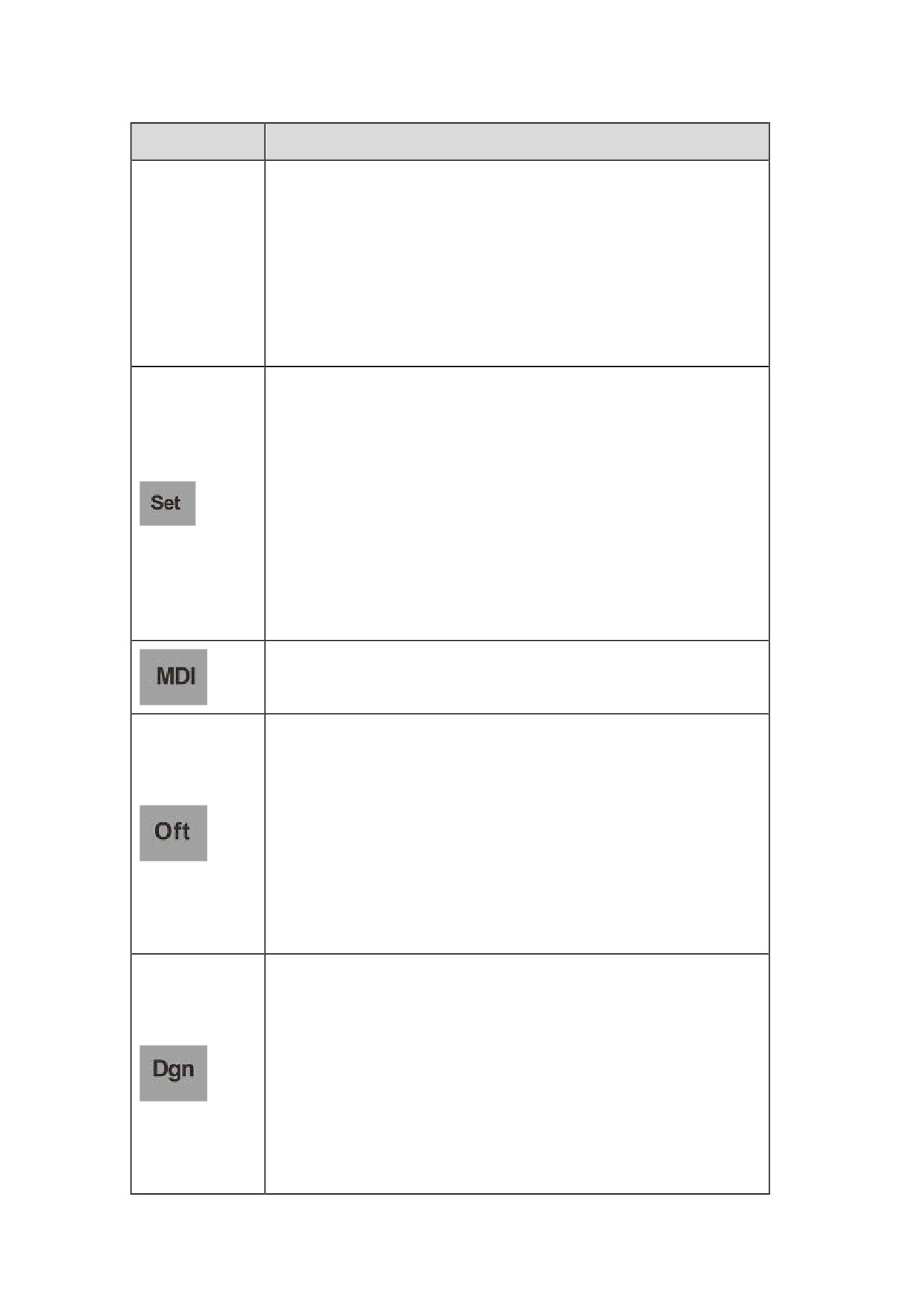
the program screen, which consists of eight submenus: OPEN, EDIT,
NEW, CUT START, GOTO, VERIFY, RESTART, and BRK.PT.
y
OPEN: to display, import, delete, open a program, or copy a
program from a USB or flash disk.
y
EDIT: to edit or save an opened program.
y
NEW: to create a new program.
y
CUT STAT: to view, edit processing information such as workpiece
3
Operation Modes and Display Screen
Menu
Description
count and processing duration.
y
GOTO: to perform operation instructed by a random row in the
current program.
y
VER: to verify a program with simulation running.
y
RESTART: to restart a program.
y
BRK.PT.: to resume and save the breakpoint in the program.
Enter the settings screen which consists of five submenus: COORD., CLR
RCS, MACRO, CLR ALM, and SKIN.
y
COORD: to define/view G54 to G59 coordinate information and
origin point offset.
y
CLR RCS: to clear axis values from the relative coordinate system.
y
MACRO: to display and predefine macro variables.
y
CLR ALM: to perform alarm settings.
y
SKIN: to set the background color displayed on the screen.
The MDI menu consists of one submenu (RETBP) that is used to edit
MDI programs and display coordinate information.
Enter the offset screen which consists of eight submenus: DIA, LEN,
XWEAR, ZWEAR, CLR X, CLR Z, X OFF, Z OFF.
y
DIA: to set X-axis offset for selected tools.
y
LEN: to set Z-axis offset for selected tools.
y
X/Z WEAR: to set wear values for selected tools.
y
CLR X/Z: to clear the defined compensation.
y
X/Z OFF: to set offset data for X/Y axis.
Enter the diagnosis screen which consists of ten submenus: I/O, REG,
ALARM, HISTORY, MEMORY, BACKUP, UPDATE, VERSION, REG,
and HELP.
y
I/O: to check Programmable Logic Circuits (PLC) status
information.
y
REG: to view the values of Register Y, R, F, G, B, and P.
y
ALARM/HISTORY: to check the current alarms and alarm history.
4
Operation Modes and Display Screen
Menu
Description
y
MEMORY: to check the system storage space, memory usage, etc.
y
BACKUP/UPDATE: to back up and update system software.
y
VERSION/REGISTER: to view system software version
information and perform registration for system software.
Enter the position screen which consist of six submenus: MCS, WCS,
UNION, TEXT, 2D and OTHER.
y
MCS: to check the position of the current program in the machine
coordinate system.
y
WCS: to check the position of the current program in the workpiece
coordinate system.
y
UNION: to check the position of the current program in the machine
coordinate, workpiece coordinate, relative coordinate systems, and
distance to go.
y
TEXT: to check the G code of the current program.
y
2D: to check the real-time processing route of the program in an
intuitive way.
y
OTHER: to check the position of the current program in the relative
coordinate system.
Enter the parameter screen where you can check and set various
parameter information.
1.1.3 Machine Operation Keys
The table below describes the machine operation keys on the operation panel of Century Star HNC
Turning System with standard PLC programs.
Key
Name
Function
Description
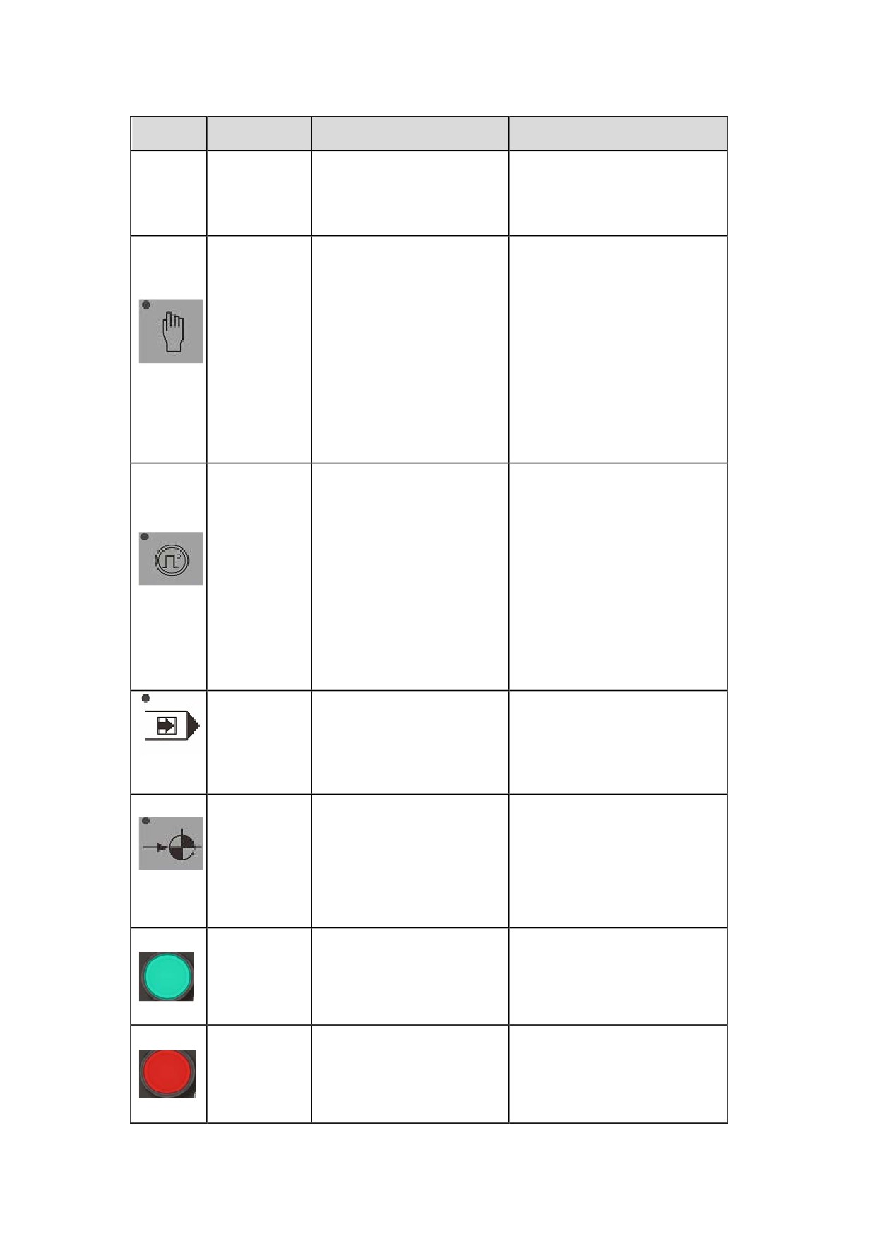
Automatically and continuously
Enter the automatic
process workpieces; Simulate
AUTO
operation mode
and verify the processing
program; Run command in the
5
Operation Modes and Display Screen
Key
Name
Function
Description
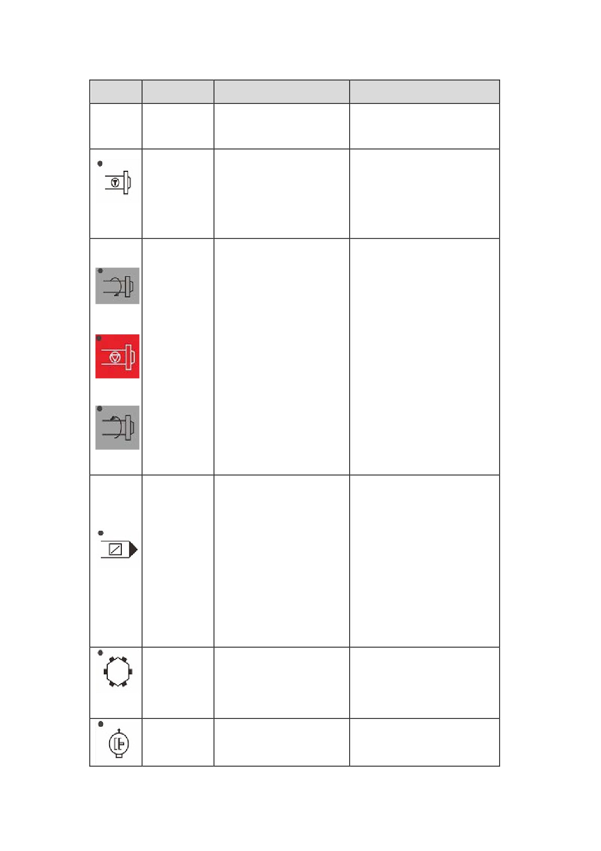
MDI mode
Manually change tools, control
machine axis, clamp/release
chucks, stretch and shrink
Enter the manual operation
Manual
tailstock, clockwise and counter
mode
clockwise rotate spindle, enable
and disable coolant, start and
stop lubrication, etc.
Step-feed or hand wheel
modes, step-feed by default.
You may press this key again
Enter the incremental
Incremental
to enter the hand wheel mode.
operation mode
This key is used to move
machine axis at a fixed
increment.
Press this key run a
Valid in the Auto and MDI
Single Block
program by block.
modes.
Valid in the Reference mode.
Reference
Enter the Reference mode.
Press this key to
Valid in the Auto mode, Single
Start
automatically process or
Block mode, and MDI mode.
simulate processing
Press this key to pause the
Valid in the Auto mode and
Feed-hold
feed operation, and press the
Single Block mode
Start key again to proceed
6
Operation Modes and Display Screen
Key
Name
Function
Description
with the ongoing feed
operation.
This key is used to
Valid in the manual mode, hand
clockwise rotate the spindle
Spindle jog
wheel mode, and incremental
at specified speed after
mode.
each press.
Press these keys to begin
spindle rotation in the
Valid in the manual mode, hand
Spindle
clockwise and
wheel mode, and incremental
control
counter-clockwise direction
mode.
or stop the spindle rotation.
Press this key to bypass
program blocks that start
Valid in the Auto mode, Single
Block Bypass
with a "/" symbol. Disable
Block mode, and MDI mode.
this key, and the bypass
function is invalid.
After pressing this key, the
Valid in the manual mode, hand
Turret rotate
turret rotates to the selected
wheel mode, and incremental
tool.
mode.
Hydraulic
Enable or disable
None
control
Hydromantic function
7
Operation Modes and Display Screen
Key
Name
Function
Description
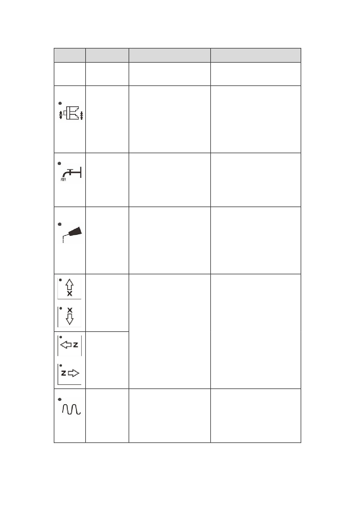
Press this key to release the
Valid in the manual mode, hand
workpiece (clamped by
Clamp/release
wheel mode, and incremental
default) for workpiece
chuck
change. Press the key again
mode.
to clamp the workpiece.
Press this key to enable or
Valid in the manual mode, hand
Coolant
disable the coolant functions.
wheel mode, and incremental
switch
This function is disabled by
mode
default.
Press this way to enable the
lubrication, and press this
Valid in the manual mode, hand
Lubrication
key again to disable the
wheel mode, and incremental
control
lubrication function
mode
(disabled by default).
Press these keys to manually
X-axis feed
move tools or workstation at
Valid in the manual mode, hand
the speed specified by the
wheel mode, and incremental
maximum processing speed
mode
and feed speed adjustment
Z-axis feed
keys.
Press this key and axis
direction keys to speed up
Speed up
Valid in the manual mode,
tool motion at the specified
maximum motion speed.
8
Operation Modes and Display Screen
1.1.4 Operation Interface
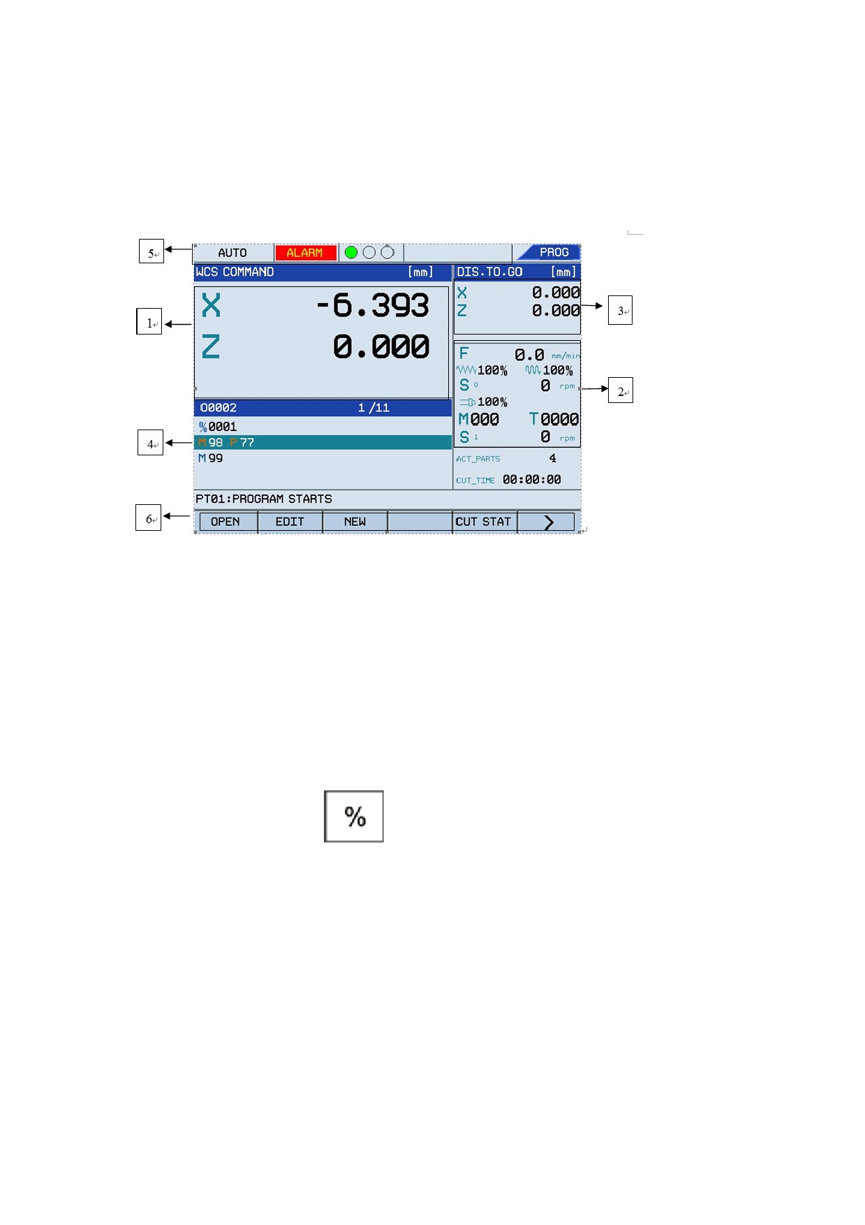
The figure below shows the operation interface of Century Star HNC Turning System:
Figure 1.2 Operation interface of Century Star HNC Turning System
1.
Main interface: Display various information for users such as machine coordinates, graphs,
alarm information, register information, and version information.
2.
Display various information such as feed rate override, rapid traverse override, spindle
override, M command, T command, feed rate, spindle rotation speed, and Metric/Inch
programming mode.
3.
Display the actual position, distance to go, origin position of the workpiece in the coordinate
system. You may use the
key in the NCP keyboard to switch information.
Note: The "distance to go" indicates the distance between the current program end
position and the actual position.
4.
Display the G code of the current program.
5.
Display the current operation mode, system running status, and three indicators status.
y
Operation mode: Switch the operation mode among Auto, Single Block, Manual,
Hand Wheel, Reference, Emergency Stop, and Reset.
y
System running status: The message "ALARM" will be displayed if an alarm or error
occurs.
9
Operation Modes and Display Screen
y
Three indicators: You may rotate the three adjustment buttons on the operation panel
to display the spindle and feed axis operation status in automatic operation. Green light
indicates the spindle can rotate and the feed axis can normally move. Yellow light
indicates the spindle can rotate but the feed axis cannot move. Red light indicates the
spindle cannot rotate and the feed axis cannot move.
6.
Display system or PLC messages.
1.2 Overview of Operation Modes
Century Start HNC Turning system provides seven operation mode: Auto, MDI, Single Block,
Manual, Reference, Hand Wheel, and Incremental modes.
A. Automatic mode
In the Automatic mode, workpiece can be machined automatically based on a program.
B. Manual Data Input mode
In the Manual Data Input mode, you may input parameters, and input and execute code.
C. Single Block mode
In the Single Block mode, a program can be run based on defined blocks.
D. Manual mode
In the manual mode, you may manually perform various operation such as manually feed, speed
up, change federate and speed up rate, start and stop spindle, enable and disable coolant and
lubrication functions, enable spindle jog, and change tools.
E. Reference mode
In the reference mode, each feed axis can home exactly to its reference point.
F.
Hand wheel mode
In the hand wheel mode, you may control each feed axis motion by manual pulse generator.
G. Incremental mode
In the hand wheel mode, press the hand wheel key again to switch to the incremental mode. In the
incremental mode, the tool can be moved a number of steps along any axis by pressing the Axis
keys. The incremental ratio can be defined by adjusting the feed override ratio.
1.3 Display Screen
This section describes how to switch among submenus, relationship between operations and soft
10
Operation Modes and Display Screen
keys, and detailed operation methods.
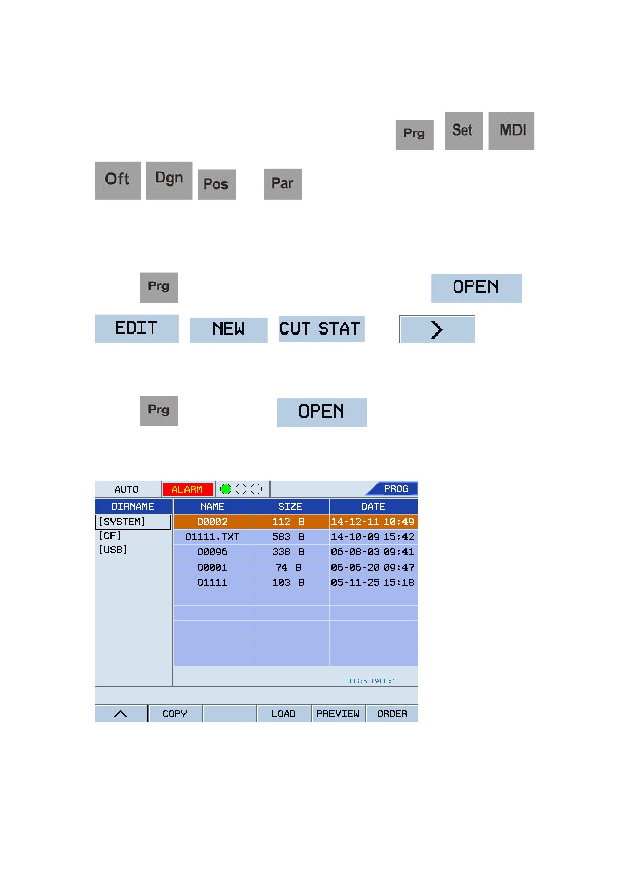
Century Star HNC turning system provides seven functional keys (
,
,
,
,
,
,and
). Each functional key corresponds a main screen
which consists of multiple submenus.
1.3.1 Program
Press the
key to enter the programming screen which consists of
,
,
,
, and
.. You may
press keys from F1 to F6 to enter corresponding submenus as required.
1.
OPEN
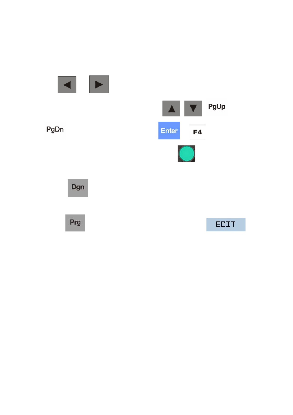
Press the
key and then the F1
key to enter the screen that displays
programs on each storage. See the figure below:
Figure 1.3 Select a program
The storage cards include:
y
SYSTEM: programs in system built-in disk
11
Operation Modes and Display Screen
y
CF: programs in the CF card
y
USB: programs in the USB
If no storage card is selected, the programs saved in the buffer space previously will be displayed.
Press
and
to switch the program storage card (can display only the programs
in the root directory) and program list screens. Press the
,
,
and
keys to select programs to be run, and press
or
to confirm and add
the selected programs. In the Auto or Single Block mode, press
to run the program. If an
error occurs, the message "ALARM" will be displayed and the indicator blinks continuously. You
may press
to check alarm information.
2.
EDIT
Press the
key, select a program to be edited, and then press the F2
key to enter the screen that displays programs on each storage card. See the figure below:
12
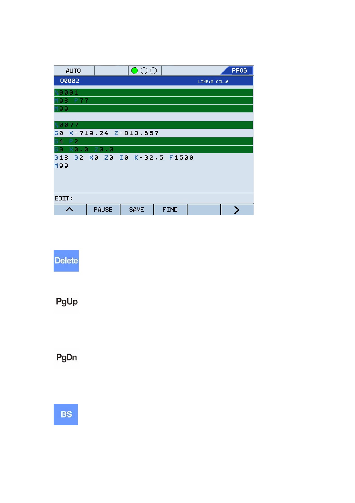
Operation Modes and Display Screen
Figure 1.4 Select a program to edit
The shortcut keys used for editing are as below:
: Delete the character behind the cursor and maintain the cursor position. The remaining
characters to the right of the cursor will move left with one-character space.
: Move the program to be edited one screen up to the program header and maintain the
cursor position. If it has reached the program header, the cursor will move to the first character in
the first row of the program.
: Move the program to be edited one screen down to the program end and maintain the
cursor position. If it has reached the program end, the cursor will move to the first character in the
last row of the program.
: Delete the character in front of the cursor and the cursor will move left with
one-character space. The remaining characters to the right of the cursor will move left with
one-character space.
13
Operation Modes and Display Screen
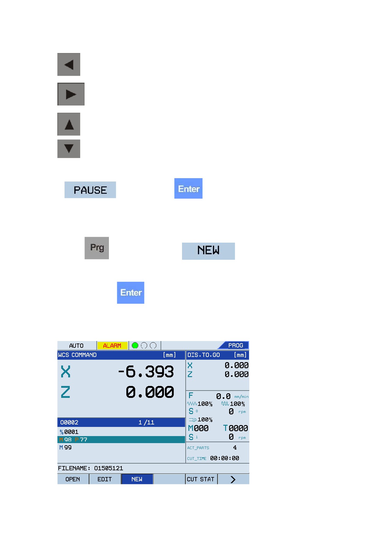
: The cursor moves left with one-character space.
: The cursor moves right with one-character space.
: The cursor moves one row upward.
: The cursor moves one row downward.
Note: The program block displayed in dark color tone cannot be directly edited. You need to press
F4
, and then press Y or
after the message "Exit the current running
Y/N? (Y)" is displayed. After that, you may edit the program.
3.
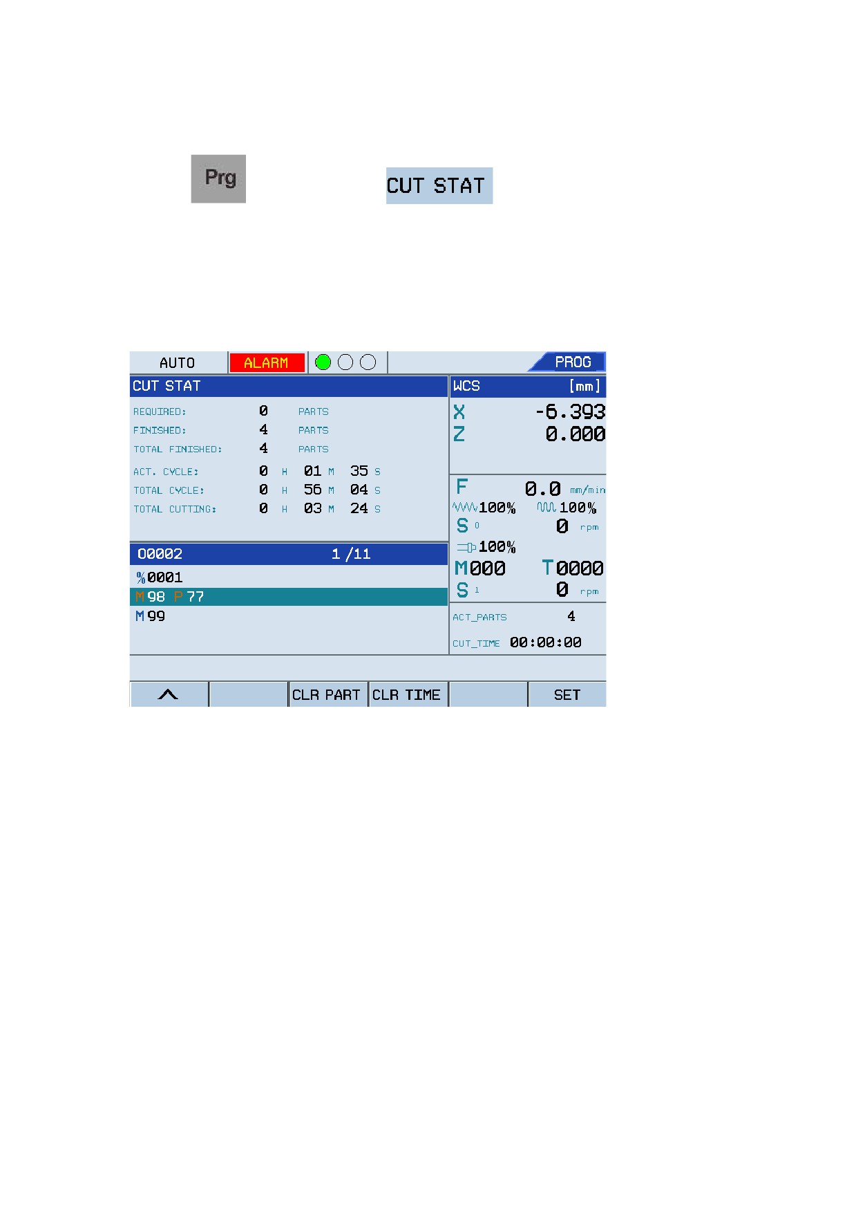
NEW
Press the
key, and then press the F3
key. The system will prompt
you to enter a new program name (a random G code name by default). After entering the program
name, you may press
to create a new program by pressing the character keys on the
NCP board. See the figure below:
Figure 1.5 Create the selected program
14
Operation Modes and Display Screen
4.
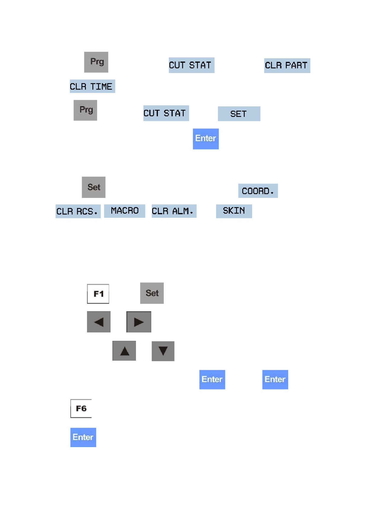
CUT STAT
Press the
key and then press F5
to enter the screen that displays
various running statistics information. This function is used to automatically perform statistics of
workpiece count and system running time, which is helpful for improving machine efficiency and
work time statistics. See the figure below:
Figure 1.6 Check system processing information
The information in the screen is described as below:
REQUIRED: The total count of workpiece (of the same type) required to be processed.
FINISHED: This indicates the workpieces that have been processed since the machine starts. The
processing period indicates that the program executed a M64 (or M30, depending on the machine
parameter 001021), and then the completed workpiece count will increase by one.
TOTAL FINISHED: The total count of workpiece that have been currently completed and
previously completed.
ACT CYCLE: The running duration since the machine starts.
TOTAL CYCLE: The current running duration together with previous running duration.
TOTAL CUTTING: The current cutting duration together with previous cutting duration.
15
Operation Modes and Display Screen
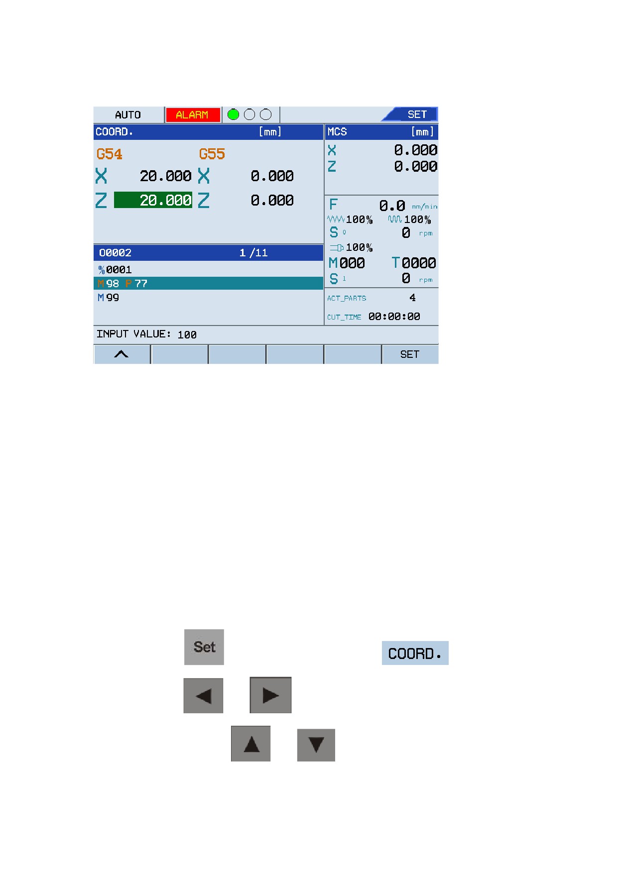
Under the
main menu, press F5
, and then press F3
or F4
to clear the workpiece count and time.
In the
menu, press F5
, press F6
, and enter the total
workpiece count required to be processed. Press the
key to confirm the settings.
1.3.2 Set
Press the
key to enter the settings screen which consists of
,
,
,
, and
submenus. You may
press keys from F1 to F6 to enter corresponding submenus as required. See the figure below:
1.
COORD.
This is used to set X and Z axis in the workpiece coordinate system when cutting a sample
workpiece.
a.
Press
under the
main menu.
b.
Press
and
to select the coordinate type to set. For example, G54-G59
and G92. Press
and
to select X or Z axis to set.
c.
Enter required coordinate information, and press
. If you press
or
in the current position as shown in the figure below, enter 20, and then press
, then the X axis value for G54 will be set to 20. Use the same method to set the
value for Z axis. The settings for other coordinates is similar like this.
16
Operation Modes and Display Screen
Figure 1.7 Set X/Y axis value
d.
Set floating origin of machine
Based on whether a Home Dog is installed, there are two methods to set the floating origin of
machine coordinate.
Method 1: If no Home Dog is defined to home the tools to the origin position (specified by
the PLC parameter 007017, default value: 0), you may set the floating origin based on the
instructions below:
•
In the manual mode, move the tool to a position where the tools will not conflict with
the workpiece or other parts, and that is appropriate to home to the origin.
•
Confirm that the position is the origin of the machine, that is, the actual coordinate
value of the point is 0.
•
Press the
key in the main menu, press the F1
submenu, and
press the
and
keys to switch to the floating origin.
•
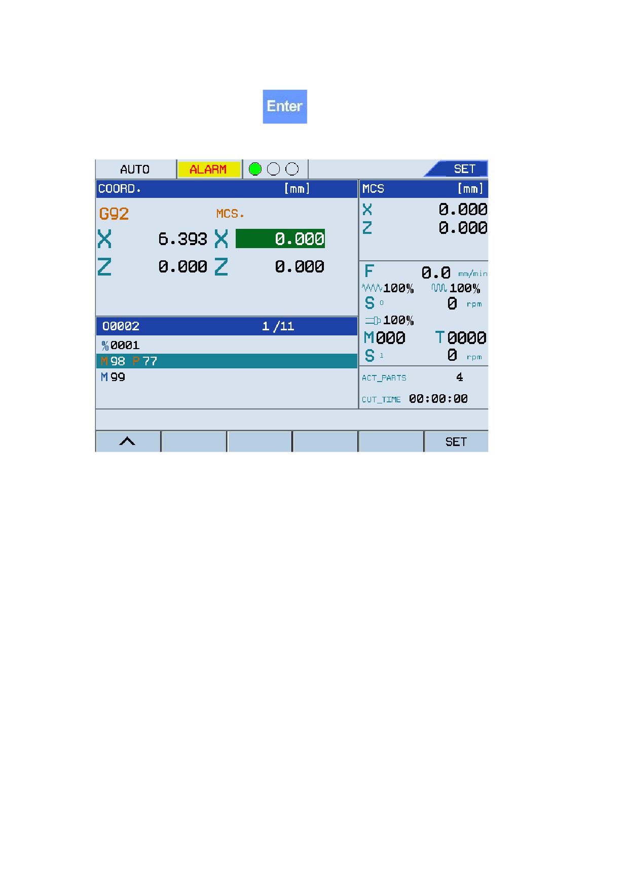
After that, press the
and
keys to select X or Y axis, enter relative
17
Operation Modes and Display Screen
coordinates, and press the
key. See the figure below:
Figure 1.8 Set floating origin
Method 2: If the Home Dog is defined to home the tools to the origin position (The PLC
parameter 007017 is set to 1), the origin of the machine coordinate system depends on the
position of the Home Dog, which is near the maximum movement distance in the positive
directions of X axis and Y axis. The position of Home Dog is fixed and the origin of the
machine coordinate system is fixed. The tool can be homed to the same position every time
you press the home key if the Home Dog is normal.
Note: After the floating origin is defined, the machine coordinate system is set. For the CNC
system without Home Dog, you need to set the floating origin first when you power on the
machine. Normally, you need to set only once, and then the tool can be homed to the same
position every time you press the home key.
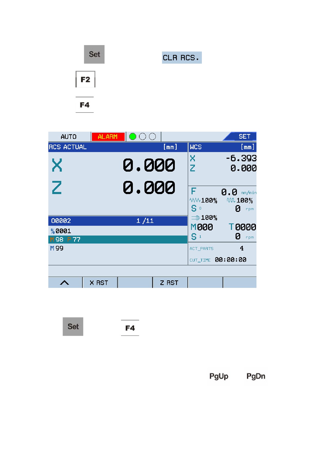
2.
CLR RCS
Follow the instructions to clear the axis values in the relative coordinate system:
18
Operation Modes and Display Screen
a.
Press the
menu, and then press F3
. See Figure 1.9.
b.
Press
, and then set the X axis value to 0 for the relative coordinate system.
c.
Press
, and then set the Z axis value to 0 for the relative coordinate system.
Figure 1.9 Clear axis value in the relative coordinate system
3.
MACRO
Press
, and then press
to enter the macro variables screen.
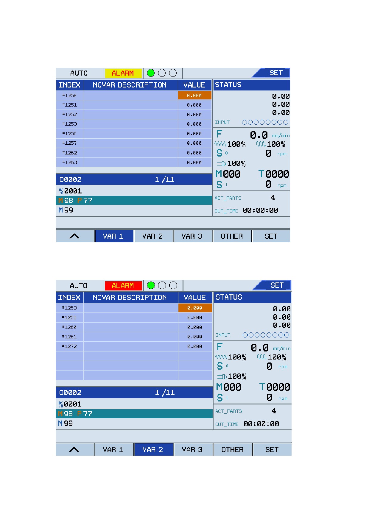
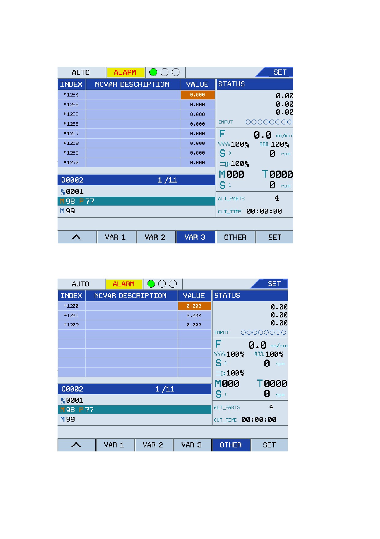
The macro variables screen consists of VAR 1, VAR 2, VAR 3, and other variables. VAR 1
includes 50 variables (#1250 to #1299). VAR 2 includes 50 macro variables (#1350 to #1399), and
VAR 3 includes 50 macro variables (#1200 to #1202). You may press
and
keys to display the subscreens as requried, and you may set macro variables either by macro code
or directly set on the keyboard. The figures below shows the variables:
19
Operation Modes and Display Screen
Figure 1.10 VAR 1
Figure 1.11 VAR 2
20
Operation Modes and Display Screen
Figure 1.12 VAR 3
Figure 1.13 Other variables
4.
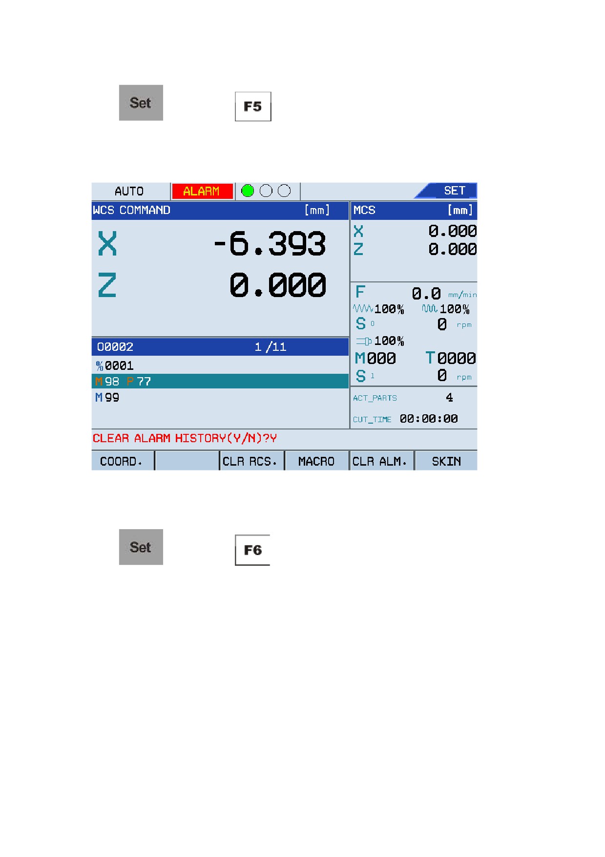
CLR ALM
21
Operation Modes and Display Screen
Press
, and then press
to enter the alarm clearing screen. The system will
prompt you whether to clear alarm history. See the figure below:
Figure 1.14 Clear alarms
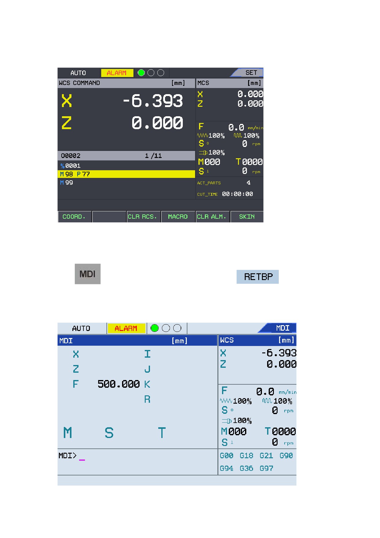
5.
SKIN
Press
, and then press
to change the system background color. The system
provides four background colors. See the figure below:
22
Operation Modes and Display Screen
Figure 1.15 Background colors
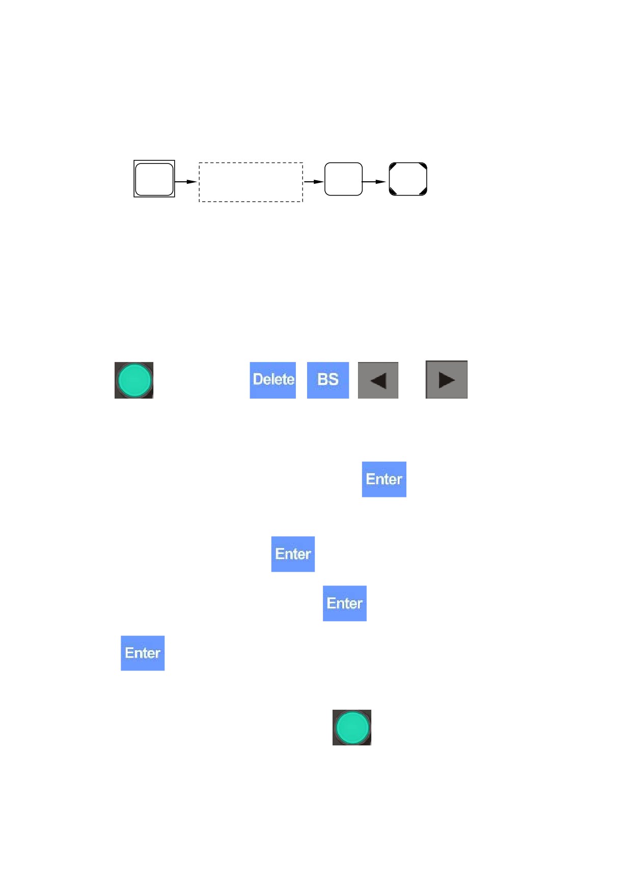
1.3.3 MDI
Press
to enter the MDI screen which includes only the
(F4) submenu.
See the figure below:
Figure 1.16 Figure MDI screen
23
Operation Modes and Display Screen
Follow the instructions below to perform manual data input:
1.
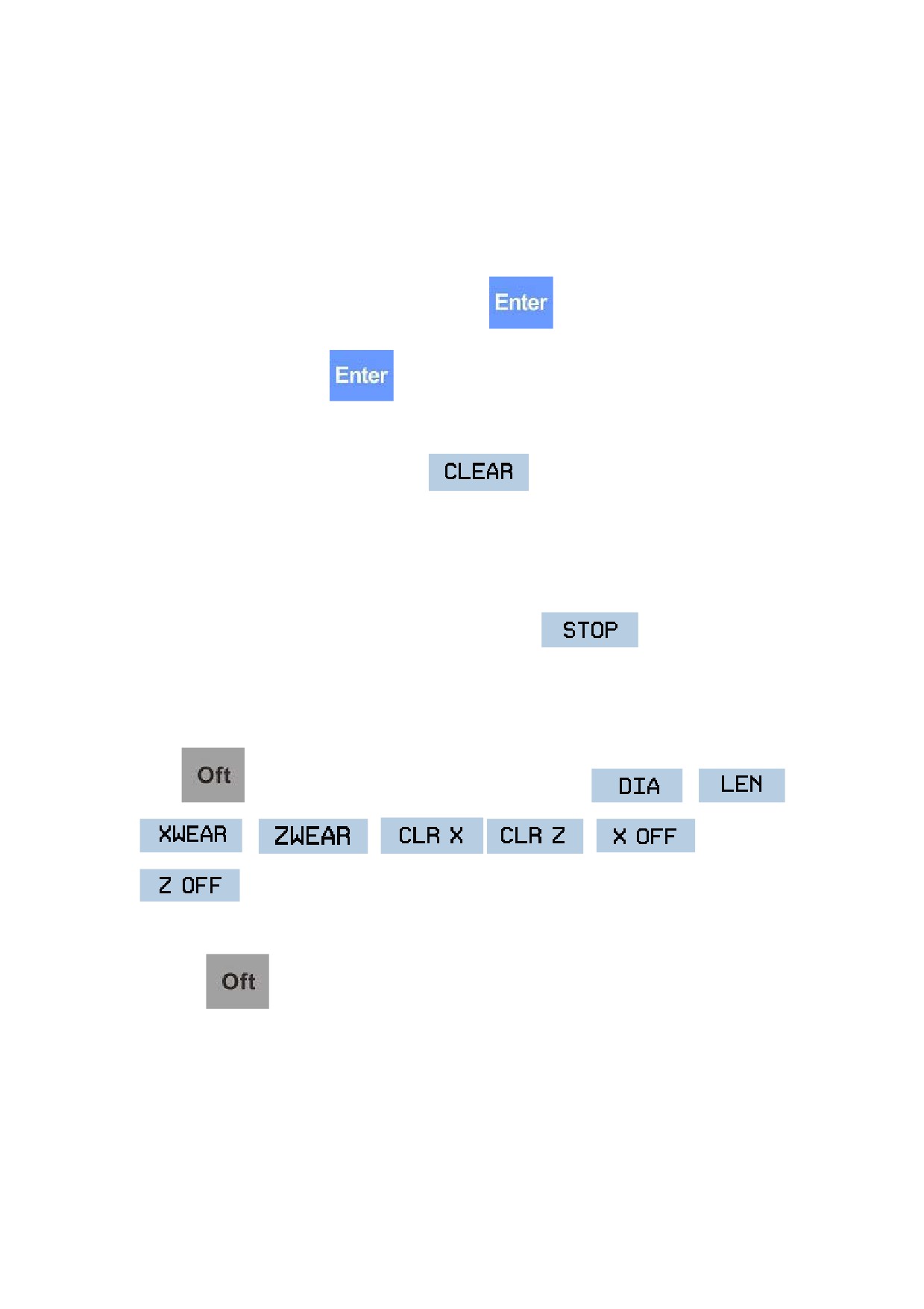
Input commands
Set the operation mode to Auto or Single Block mode:
Input command segment,
Start
MDI
ENTER
e.g
G91G01X-21Z-34 F400
The minimum unit for MDI is a valid command character. Therefore, there are two methods to
input an MDI command segment:
y
Input by once, that is, input multiple command characters once.
y
Input by several times, that is, input only one character every time.
While entering commands, you may see the entered content in the command line. Before pressing
the
key, you may press
,
,
, and
to edit as
required if a wrong command is input.
For example, if you need to input the "G00 X100 Z1000" command segments, you may:
y
Directly input "G00 X100 Z1000" and then press
. The values after G, X, Z on
the screen change to 00, 100, and 1000 respectively.
y
Input "G00" first, and then press
. The G code value displayed in the lower right
corner displays as G00. Input "X100", press
, and then input "Z1000" and press
, "X100" and "Z1000" will be displayed on the screen successively.
2.
Execute commands
After entering an MDI command segment, press the
key on the operation panel, and
then the system will run the entered MDI command.
If the MDI command is incomplete or has wrong syntax, the system will display related error
24
Operation Modes and Display Screen
messages, and the MDI command cannot be run.
3.
Modify commands
Before running MDI command, you may directly input corresponding command characters and
values in a command line if you need to modify the command character.
For example, after entering "X100" and pressing the
key, you may input "X109" in the
command line and press the
key if you need to change the X-axis value to 109.
4.
Clear the current command
After inputting MDI data, you may press F2
to clear all currently input data (other
commands are still valid), and all data after X, Z, I, K, R are cleared. You may enter new data as
required.
5.
Stop running commands
When the system running MDI commands, you may press F1
to stop running
commands.
1.3.4 Offset
Press
to enter its corresponding screen which consists of
,
,
,
,
,
,
, and
submenus.
1.
Offset
Press the
key for the first time to enter the offset settings screen.
There are two methods to set the tool offset: to manually input and to use sample cutting. The
system will automatically calculate the tool offset value based on the diameter and length. HNC
turning system supports sample cutting to set tool offset values.
Note: The offset value will be reflected in the corresponding workpiece coordinate system. The
X-axis origin point is in the centerline of the rotation axis.
25
Operation Modes and Display Screen
The content below describes the method to set offset for tools:
This method requires independent offset value for each tool, which will be reflected in the
workpiece coordinate system:
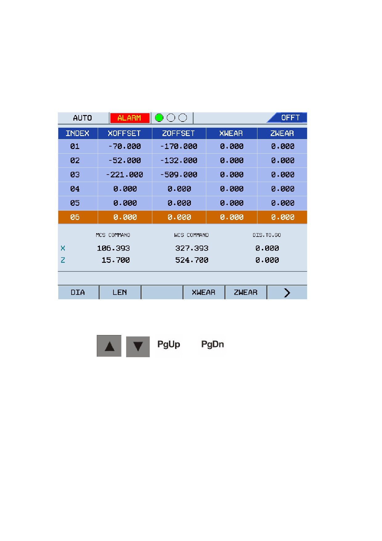
Figure 1.17 Edit tool offset
Follow the instructions below to set the tool offset:
a.
Use the
,
,
and
keys to move the cursor to the row
where you can select the required tool.
b.
Do a round face grinding on the sample workpiece, and then exit the tool along with the Z
axis (Do not move on X axis during this procedure).
c.
Measure the diameter of the sample workpiece, and then manually enter the value for the
measured diameter (DIA) as shown in Figure 1.17.
d.
Do an end face grinding with the tool on the sample workpiece, and then exit the tool along
with the X axis.
e.
Measure the distance from the tool's end face to the point of origin in the workpiece
coordinate system, and then manually enter the distance value for the Measured Length
26
Operation Modes and Display Screen
(LEN) column.
Repeat the steps above to set the offset for other tools.
Note:
• You need to home the machine to the machine origin point before setting offset.
• The directional distance from the end face of the sample workpiece to the origin point of the
workpiece coordinate system is the value on the Z axis in the workpiece coordinate system.
• Do not move the tool on the X axis after the round face grinding on the sample workpiece as
the X-axis origin offset of the workpiece coordinate system = X-axis value of the machine
coordinate system - measured diameter.
• Do not move the tool on the Z axis after the end face grinding on the sample workpiece as
the Z-axis origin offset of the workpiece coordinate system = Z-axis value of the machine
coordinate system - measured length.
2.
Tool Compensation
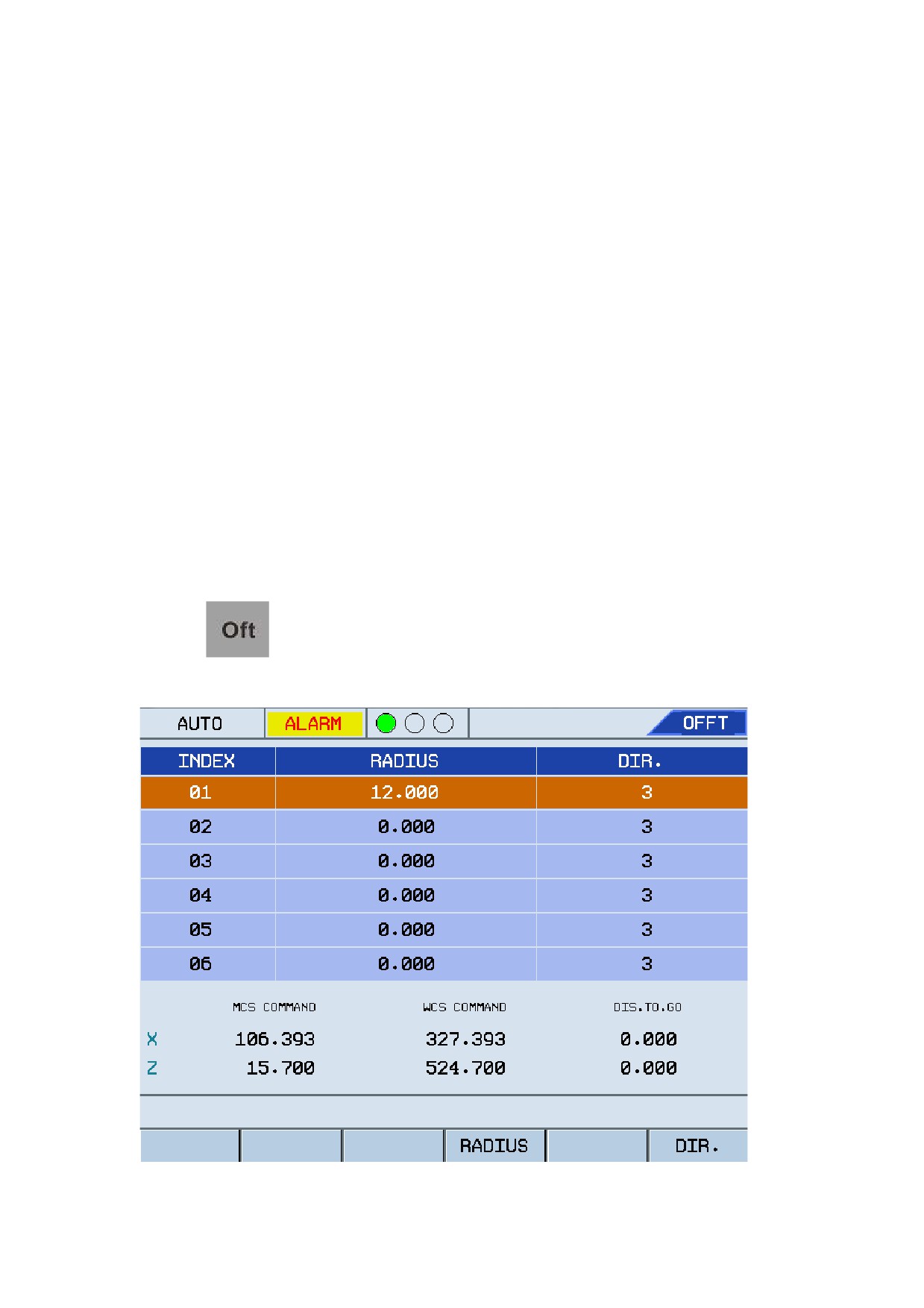
Press the
key to enter the screen as shown below:
Figure 1.18 Set tool compensation
27
Operation Modes and Display Screen
Use the
,
,
and
keys to select required tools, and press
the F5
and F6
to enter the compensation value, press the
key to confirm the value.
Definition of Direction:
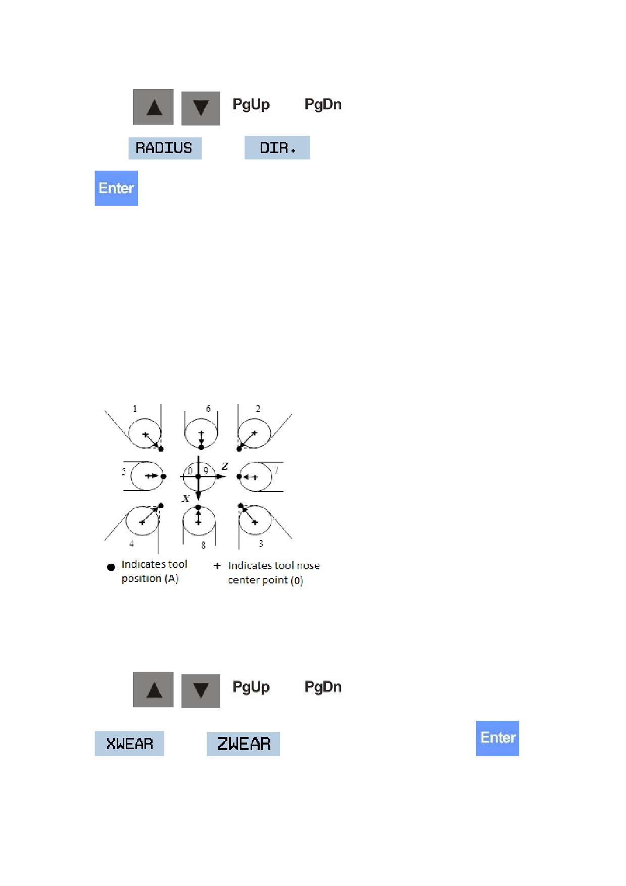
The tools of the machine can be installed in multiple directions and there are multiple modes of
tool nose. To make the CNC system know the tool installation direction and make accurate tool
nose radius compensation, we have defined the tool nose position codes.
The direction of the imaginary tool nose can be selected from the eight specifications shown
below together with their corresponding codes.
Figure 1.19 Specification of the imaginary tool nose direction
Generally, most tool nose direction is specified as No.3 tool.
3.
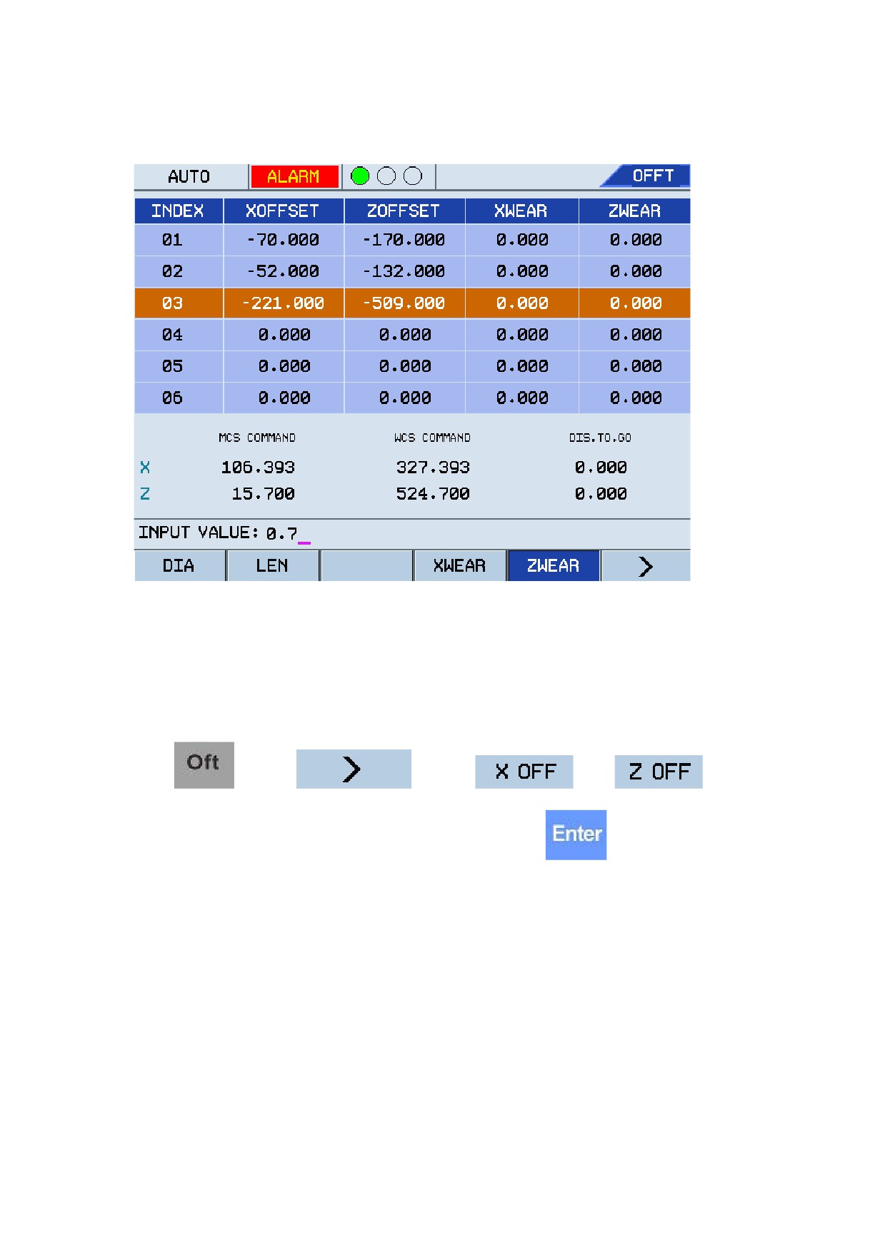
Tool wear
Use the
,
,
and
keys to select required tools, press the F5
and F6
to enter the tool wear value, and press the
key to confirm the value.
28
Operation Modes and Display Screen
Figure 1.20 Set tool wear value
Note:You may specify the machine parameter 001020 to define whether to accumulate the tool
wear values.
4.
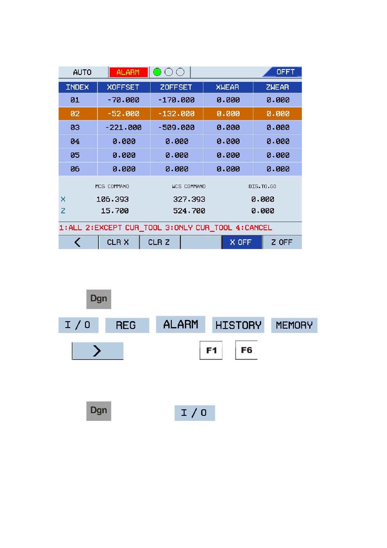
X/Z Offset
Press
, press F6
, select F5
or F6
, enter
the offset value in the input box, such as "16", and then press the
key to confirm the
value. The system will display a message "1: ALL 2: EXCEPT CUR_TOOL 3: ONLY
CUR_TOOL 4: CANCEL", where:
y
1 indicates to perform offset for all tools including the current tool.
y
2 indicates to perform offset for all other tools except for the current tool.
y
3 indicates to perform offset for only the current tool.
y
4 indicates to cancel the offset.
29
Operation Modes and Display Screen
Figure 1.21 Set X/Y offset
1.3.5 Tool Diagnosis
Press the
key to enter the diagnosis screen which consists of six submenus:
,
,
,
,
,
and
. You may press keys from
to
and enter corresponding
submenus as required.
1.
I/O
Press the
key and then press F1
to view the 128 groups of signals for
each X Input and Y Output.
30
//////////////////////