HSD2 Series Servo Drive. User Manual - page 3
(mm)
The ideal range of the gear ratio is from 1/50 to 50.
Electronic
Gear Ratio
1~
13
Refer to parameter PA12
(Denominato
30000
r) M1
Position
Note the revised parameters will only be effective
command
after you turn the power off and on again in
Pulse Input
completion of the changes.
Type
There are three different types of pulse input:
0:pulse + direction.
14
0~2
1:CCW pulse + CW pulse.
2:AB phase pulse.
Definitions of CCW and CW: face the motor,
anti-clockwise direction is CCW(positive) while
clockwise running direction is CW(negative).
Position
0:Normal direction
command
1:Negative direction
15
0~1
Pulse
Direction
Positioning
In PT mode, this parameter is used to monitor the
Completed
pulse range for the completion of the position
Range
controlling. The servo drive will need to use this
0~
value to judge whether or not the position control is
16
30000
completed.
pulse
In the position control mode, the COIN signal will
be on when the leftover pulse of the position error
is less then set value of PA16.
Excessive
Users can set position error detection range by
0~
Position
adjusting this parameter. Under the position control
30000
17
Error
mode, if the actual position error exceeds to the set
×100
Detection
value, the servo drive will send the alarm signal..
pulse
Range
Excessive
0:Enable detection function for excessive position
Position
error.
18
Error
0~1
1:Disable the function for detecting the position
selection
error.
mode
Smooth
This filter is used to smooth the position command
0~
19
Constant of
pulse, value means the smooth constant.
30000
57
Position
Command pulse going through the filter won’t
×0.1Ms
Command
cause any pulse lose, but result in command
delays.
When the set value is 0, this means the filter is
disabled.
This filter will be used under the following
circumstances:
The host controller does not have a deceleration /
acceleration function.
The electronic gear ratio is larger than 10.
The position frequency is low. ;
Step jumping and vibration occur when the motor
is running.
Inhibition
0:Enable the inhibition function for both CCW and
Function
CW, when the drive inhibition switch(FSTP) is ON,
Selection
drive inhibition enabled, when it’s in OFF status,
the CCW torque value maintains at 0.(Same as
CW direction operation).
20
If both CCW and CW drive inhibitions are OFF, it
0~1
will trigger the alarm.
Cancel CCW and CW input inhibition, whether the
FSTP is ON or off, both CCW and CW are enabled,
in the meantime, if you turn both CCW and CW
drive inhibitions off, it won’t trigger any alarms.
JOG
-3600~3
Set the operation speed command for JOG control
21
Operation
600
mode.
Command
r/min
Torque
*Set the characteristics of torque instruction filter;
filtering time
*Used to suppress resonance generated by torque;
constant
*If the moment of inertia of the load is very large,
PA22 can be increased appropriately. If the value is
too large, the response will slow down, which may
0~1000
22
cause oscillation.
*0.1ms
*The smaller the value, the higher the cutoff
frequency and the faster the response. If a higher
torque response is required, the set value can be
reduced appropriately.
Speed
0: External analog input( analog voltage between
23
Command
AS+,AS- to control the speed)
0~5
selection
1:select the
1st speed command(determined by
58
PA24)
2: select the 2nd speed command(determined by
PA25)
3: select the 3rd speed command(determined by
PA26)
4: select the 4th speed command(determined by
PA27)
5:select the speed command via SC2, SC1
SC2=0,SC1=0,select the 1st speed command
SC2=0,SC1=1,select the 2nd speed command
SC2=1,SC1=0,select the 3rd speed command
SC2=1,SC1=1,select the 4th speed command
1st Speed
Set inner speed 1
-3600
24
Command
~3600
r/min
2nd Speed
Set inner speed 2
-3600
25
Command
~3600
r/min
3rd Speed
Set inner speed 3
-3600
26
Command
~3600
r/min
4th Speed
Set inner speed 4
-3600
27
Command
~3600
r/min
Target Motor
1.this parameter is used to set the targeted speed
Speed
value;
2.Under the non position control mode, if the
detected motor speed is over the set value, the
0~3600
28
SCMP will be ON, otherwise, the SCMP is OFF.
r/min
3.There is no need to use this parameter under
position control mode
4.The motor speed has nothing to do with the
rotating directions.
Analog
Set the proportional relationship between analog
Torque
input voltage and the value of torque command.
Command
This function is effective only under the torque
10~100
29
Gain
control mode (PA4=2).
(0.1V/10
The unit is 0.1V/100%.
0%)
The default is 50, which means it will produce
100% rated torque by inputting 5v voltage.
59
Direction of
0:The direction of the torque is CCW
Analog
1:The direction of the torque is CW
30
0~1
Torque
Command
Zero-offset
The value is the offset compensation for the analog
Compensatio
signal of torque command.
-2000
31
n for Torque
~2000
Command
Max speed
In torque control mode, this setting will limit the
0~3600
32
Limit under
max running speed of the servo motor.
r/min
torque mode
DO status
1.monitoring the output level status for the 3 DO
monitoring
ports
2.Bit0
corresponds to DO1; Bit1 corresponds to
DO2; Bit2 corresponds to DO3;Under the default
parameters setting status: bit0=ALR ; bit1=coin;
33
111
bit2=BRK
3.When Bitx=1,it means the related DO port output
high level
When Bitx=0, it means the related DO port
output low level.
DI
status
1.monitoring the input level status for the 4 DI ports
monitoring
2.Bit0 corresponds to DI1; Bit1 corresponds to DI2;
Bit2 corresponds to DI3;Bit3 corresponds to DI4.
Under the default parameter setting status,
34
bit0=SON;bit1=CLE/SC1;bit2=SC2;bit3=ALRS
1111
3.When Bitx=1,it means the related DI port input
high level
When Bitx=0, it means the related DI port input
low level.
Max speed
Limit the max speed of motor, when you’ve done
0~3600
35
limit of motor
the parameter settings, turn the power off and on
r/min
again to enable the changes.
Internal
Control the drive torque output,
36
5~400%
torque limit
T max=PA36*T rated *1%.
Negative
When negative torque arrived at the set point, the
torque
TRQL signal output is active.But this value should
37
5~300%
arrived
not considered as the limited negative torque set
set point
point, the torque limit should be set by PA36.
38
Positive
1.Under the position control mode,PA38 is set as
5~300%
60
torque
the positive torque arrived at the set point,theTRQL
arrived
signal output is active. But this value should not
set point/
considered as the limited positive torque set point.
Maximum
2.under the trial run
(PA4=3) and Jog
torque limit in
mode(PA4=4), PA38 is the limit parameter of the
test run and
max torque output.And the max drive output torque
JOG mode
will be the lower value between PA36 & PA38.
Min speed
limit for
PA4=1 means it’s in analog speed control mode,
0~1000
39
Analog
this parameter is used to control the min speed of
r/min
speed
the motor.
control mode
Acceleration
1.set value indicates the acceleration time for the
Time
motor to reach the speed from 0 to 1000r/min.
2.It has a linear feature.
3.Only used under the speed control mode.
0~1000
40
4.If the drive is being used together with
the
0Ms
external position loop, please set PA40=0.
5.This parameter is effective when PA4=1
or
PA4=4.
Deceleration
1.set value indicates the acceleration time for the
Time
motor to reach the speed from 0 to 1000r/min.
2.It has a linear feature.
3.Only used under the speed control mode.
0~1000
41
4.If the drive is being used together with
the
0Ms
external position loop, please set PA40=0.
5.This parameter is effective when PA4=1
or
PA4=4.
Acc/Dec
Stabilize the motor start-up and stop, set
the
S-curve
S-curve continuous time for acceleration or
0~1000
42
deceleration.This parameter is effective when
0Ms
PA4=1 or PA4=4.
Analog
Set the proportional relationship between analog
Speed
input voltage and the speed command.
10~300
43
Command
Only when PA4=1 and PA23=0, or PA4=2, the
0
Gain
function is active.
r/min/V
Direction of
Select the direction for the external speed
44
analog
command.
0~1
Speed input
0: When analog speed command is positive, the
61
Command
speed direction is CCW.
1: When analog speed command is negative, the
speed direction is CW.
Zero-offset
Compensatio
This is the analog speed command zero speed
-2000
45
n for Analog
clamp value.
~2000
Speed
Command
Low-pass
1.this is a low-pass filter working on analog input.
Filter for
2.Increase the set value will down grade the
Analog
response performance but eliminate the noise
Command
impact to the signal.
0~1000
46
3.this parameter is only active under the following
ms
conditions.
1. PA4=1 and PA23=0
2. PA4=2.
Enable
Set the delay time between output terminal(BRK)
Delay time of
ON to OFF and the actual current cut-off.
0~300
47
the
This value shall not be lower than the mechanical
×10Ms
electromagn
brake delay time.
etic Brake
Disable
Set the delay time between current cut-off and
Delay
output terminal(BRK) OFF to ON. When the motor
Time of the
is running at a very high speed, wait until it slows
electromagn
down and enable the brake will protect the brake
0~300
48
etic Brake
from potential damage. The actual time is the
×10Ms
lowest one between PA48 and the required time for
the motor to decrease the speed to the set value of
PA49.
Brake
Set the brake working speed from current cut-off to
operating
mechanical brake enabled,(output terminal BRK
0~3600
49
speed when
from ON to OFF)
r/min
the motor is
running
Sampling
It is used to compensate the voltage offset for the
10~300
50
Gain for Bus
input DC Bus. This parameter is not allowed to be
0
Voltage
changed.
Dynamic
0:dynamic gear ratio invalid, the function of the
51
0~1
Gear ratio
input terminal INH is to disable the pulse
62
command, gear ratio is decided by PA12/PA13
1:dynamic gear ratio is effective, the function of the
input terminal INH is to switch over the gear, when
INH is in an invalid electric level,(valid electric level
is set by PA62), gear ratio is decided by
PA12/PA13, when INH is in an valid electric level,
the gear ratio is PA52/PA13.
Electronic
gear
The function is the same as PA12, only effective
52
ration( numer
when there is INH signal.
ator)
SON Force
0: the drive can’t be force enabled.
53
enable
1:the drive can be force enabled.
0~1
position
Z output
0: output original Z pulse signal without processing
pulse
1:output Z pulse signal with a bandwidth min
54
0~1
bandwidth
0.2ms.
select
Position
0:output original AB pulse signal
encoder AB
1,AB signal output bandwidth is 10.
55*
signal output
0~1
dividing
factor
DO output
This parameter is to define the electric
level
of
effective
output terminals BRK COIN ALM
electric level
Symbol
DO3
DO2
DO1
default
(BRK)
(COIN)
(ALM)
Control
position
PA56.2
PA56.1
PA56.0
56
000~111
PA56.2=0,BRK effective level is low;
PA56.2=1,BRK effective level is high.
PA56.1=0,COIN effective level is low;
PA56.1=1,COIN effective level is high.
PA56.0=0,ALM effective level is low;
PA56.0=1,ALM effective level is high.
DO1(ALM)se
DO has three actual output terminals, four
lf define
functions:
57
1~5
PA57=1,DO1 is fined as ALM; servo is alarm;
PA57=2,DO1 is defined as SRDY; servo is ready;
63
PA57=3,DO1
is
defined
as COIN;when
PA4=0,COIN means position reached,when
PA4=1, it means speed reached.
PA57=4,DO1 is defined as BRK; control brake
PA57=5,DO1 is defined as TRQL; Torque arrived
DO2(COIN)
Refer to PA57
58
1~5
self define
DO3(BRK)
Refer to PA57
59
1~5
self define
60
Reserved
Input filtering
1. Define the input filtering time constant.
time constant
2. The lower this value is, the better response
performance you will get, but in the meantime, it’ll
0~100m
61
be very easy to introduce interference.
s
3. The bigger this value is, the poorer response
you will get, but you will get a better
anti-interference performance.
Input
This parameter is to define the electric level of input
terminal DI
terminal DI:
effective
Symbol
DI4
DI3
DI2
DI1
electric level
Default
self define
definition
(ALRS)
(SC2)
(CLE)
(SON)
Control
position
PA62.3
PA62.2
PA62.1
PA62.0
0000
62
PA62.3=0,DI4 effective level is low;
~1111
PA62.3=1,DI4 effective level is high;
PA62.2=0,DI3 effective level is low;
PA62.2=1,DI3 effective level is high;
PA62.1=0,DI2 effective level is low;
PA62.1=1,DI2 effective level is high;
PA62.0=0,DI1 effective level is low;
PA62.0=1,DI1 effective level is high;
DI1(SON)
DI1 has 4 actual output terminals,with 7 different
self define
functions:
PA63=1,DIx is defined as SON, servo on;
PA63=2,DIx is defined as CLE/SC1/ZCLAMP;
63
1~7
PA63=3,DIx is defined as INH/SC2;
PA63=4,DIx is defined as ALRS;
PA63=5,DIx is defined as FSTP;
PA63=6,DIx is defined as RSTP;
64
PA63=7,Dix is defined as AIR;Analog input reverse.
DI2(CLE)
Refer to PA63
64
1~7
self define
DI3(SC2)self
Refer to PA63
65
1~7
define
DI4(ALRS)
Refer to PA63
66
1~7
self define
Note1: “*” next to the parameter numbers means this function may be “reserved” for some
models, for instance,55*, it may not exist or just reserved in some models, the detailed information,
please consult with our after sales service center or local distributors.
65

Chapter 7
Motor Type Matching
Before you power the servo drive, please make sure the motor is properly selected
and all parameters are set correctly, otherwise, it may cause malfunction, trigger the
alarms off, or the motor may lose its control.
You need to input the password,(set PA0=302) before you modify the parameter
PA1.
When you’ve done setting of PA1, please write(save) the parameters into servo
drive(when the panel displays EE-SET, press the
Enter key for 3 seconds until it
displays ”FINISH”, this means the parameters are saved in the drive). Then power OFF
and ON again, the set parameters will be effective.
Generally, please follow the following list when you are selecting the motor type:
Drive HSD2-020 is adaptive for 60, 80, 90, and 110 series motor.
Drive HSD2-030/030A is adaptive for 80, 90, 110 and 130 series motor.
Drive HSD2-050 is adaptive for 110, 130 and 150 series motor.
Drive HSD2-065 is adaptive for 130, 150 and 180 series motor.
If client want to match other motors which is not produced by our company, please
consult with your local distributor or our technical department.
66
7.1
Motor Type List for HSD2-020
Table 7-1
Motor type list for HSD2-020
Torqu
Rated
Rated
Power
Code
Motor model
e
Speed
Current
(kw)
(Nm)
(rpm)
(A)
21
S60-2-006M30
0.2
0.6
3000
1.5
23
S60-2-013M30
0.4
1.3
3000
2.8
25
S60-2-019M30
0.6
1.9
3000
3.5
31
S80-2-013M30
0.4
1.3
3000
2.6
33
S80-2-024M30
0.75
2.4
3000
4.2
35
S80-2-033M30
1
3.3
3000
4.5
41
S90-2-024M30
0.75
2.4
3000
3
45
S90-2-035M20
0.75
3.5
2000
3
48
S90-2-040M25
1
4
2500
4
51
S110-2-020M30
0.6
2
3000
4
53
S110-2-040M30
1.2
4
3000
5
56
S110-2-060M30
1.2
6
2000
6
others
S80-2-024M30
0.75
2.4
3000
4.2
67
7.2
Motor Type List for HSD2-030
Table 7-2
Motor type list for HSD2-030
Powe
Rated
Rated
Torque
Code
Motor model
r
Speed
Current
(kw)
(Nm)
(rpm)
(A)
31
S80-2-013M30
0.4
1.3
3000
2.6
33
S80-2-024M30
0.75
2.4
3000
4.2
35
S80-2-033M30
1
3.3
3000
4.5
41
S90-2-024M30
0.75
2.4
3000
3
45
S90-2-035M20
0.75
3.5
2000
3
48
S90-2-040M25
1
4
2500
4
51
S110-2-020M30
0.6
2
3000
4
53
S110-2-040M30
1.2
4
3000
5
55
S110-2-050M30
1.5
5
3000
6
56
S110-2-060M30
1.2
6
2000
6
61
S130-2-040M25
1
4
2500
4
63
S130-2-050M20
1
5
2000
4.5
64
S130-2-050M25
1.3
5
2500
5
65
S130-2-050M30
1.5
5
3000
6
67
S130-2-060M25
1.5
6
2500
6
69
S130-2-077M20
1.6
7.7
2000
6
72
S130-2-100M10
1
10
1000
5
73
S130-2-100M15
1.5
10
1500
6
Others
S110-2-040M30
1.2
4
3000
5
68
7.3
Motor Type List for HSD2-050
Table 7-3
Motor type list for HSD2-050
Rated
Rated
Power
Torque
Code
Motor model
Speed
Current
(kw)
(Nm)
(rpm)
(A)
51
S110-2-020M30
0.6
2
3000
4
53
S110-2-040M30
1.2
4
3000
5
55
S110-2-050M30
1.5
5
3000
6
56
S110-2-060M30
1.2
6
2000
6
58
S110-2-060M30
1.8
6
3000
8
61
S130-2-040M25
1
4
2500
4
63
S130-2-050M20
1
5
2000
4.5
64
S130-2-050M25
1.3
5
2500
5
65
S130-2-050M30
1.5
5
3000
6
67
S130-2-060M25
1.5
6
2500
6
69
S130-2-077M20
1.6
7.7
2000
6
70
S130-2-077M25
2
7.7
2500
7.5
71
S130-2-077M30
2.4
7.7
3000
9
72
S130-2-100M10
1
10
1000
5
73
S130-2-100M15
1.5
10
1500
6
75
S130-2-100M25
2.6
10
2500
10
78
S130-2-150M15
2.3
15
1500
9.5
79
S130-2-150M25
3.8
15
2500
17
82
S150-2-150M20
3
15
2000
14
83
S150-2-150M25
3.8
15
2500
17
86
S150-2-180M20
3.6
18
2000
16.5
Others
S130-2-077M20
1.6
7.7
2000
6
69
7.4
Motor Type List for HSD2-065
Table 7-4
Motor type list for HSD2-065
Rated
Rated
Power
Torque
Code
Motor model
Speed
Current
(kw)
(Nm)
(rpm)
(A)
65
S130-2-050M30
1.5
5
3000
6
67
S130-2-060M25
1.5
6
2500
6
69
S130-2-077M20
1.6
7.7
2000
6
70
S130-2-077M25
2
7.7
2500
7.5
71
S130-2-077M30
2.4
7.7
3000
9
72
S130-2-100M10
1
10
1000
5
73
S130-2-100M15
1.5
10
1500
6
75
S130-2-100M25
2.6
10
2500
10
78
S130-2-150M15
2.3
15
1500
9.5
79
S130-2-150M25
3.8
15
2500
17
82
S150-2-150M20
3
15
2000
14
83
S150-2-150M25
3.8
15
2500
17
86
S150-2-180M20
3.6
18
2000
16.5
89
S150-2-230M20
4.7
23
2000
20.5
92
S150-2-270M20
5.5
27
2000
20.5
94
S180-2-172M15
2.7
17.2
1500
10.5
95
S180-2-190M15
3.0
19
1500
12
96
S180-2-215M20
4.5
21.5
2000
16
97
S180-2-270M15
4.3
27
1500
16
98
S180-2-350M10
3.7
35
1000
16
99
S180-2-350M15
5.5
35
1500
19
Other
S150-2-150M15
2.3
15
1500
9.5
s
70
HSD2
Series AC
Servo
Drive
7.5
Motor Type List for HSD2-030A
Table 7-5
Motor type list for HSD2-030A
Power
Torque
Rated speed
Rated
Code
Motor Model
(Kw)
(N.m)
(rpm)
current
(A)
22
60ST-006M30
0.2
0.64
3000
1.2
23
60ST-013M30
0.4
1.27
3000
2.8
24
60ST-019M30
0.6
1.91
3000
3.7
25
80ST-013M30
0.4
1.3
3000
2.6
26
80ST-024M30
0.75
2.4
3000
4.2
27
80ST-033M30
1
3.3
3000
4.2
30
80ST-040M25
1
4
2500
4.4
31
90ST-024M30
0.75
2.4
3000
3
32
90ST-035M20
0.75
3.5
2000
3
33
90ST-040M25
1
4
2500
4
34
110ST-020M30
0.6
2
3000
4
35
110ST-040M30
1.2
4
3000
5
36
110ST-050M30
1.5
5
3000
6
37
110ST-M06020
1.2
6
2000
6
38
110ST-060M30
1.8
6
3000
8
44
130ST-040M25
1.0
4
2500
4
45
130ST-050M25
1.3
5
2500
5
46
130ST-060M25
1.5
6
2500
6
47
130ST-077M20
1.6
7.7
2000
6
48
130ST-077M30
2.4
7.7
3000
9
49
130ST-100M15
1.5
10
1500
6
50
130ST-100M25
2.6
10
2500
10
51
130ST-150M15
2.3
15
1500
9.5
52
130ST-120M20
2.4
12
2000
10
Others
110ST-040M30
1.2
4
3000
5
71
Chapter 8
Alarm, Protection Function & Troubleshooting
When any trouble occurs, the “Err xx” would be shown on the digital keypad and
blink. “xx” is the code for the error kind. The common errors are Err 3, Err 9, Err 11, Err
13, Err 17 and Err 38, which caused by improper wiring or mechanical problem.
8.1
Alarm Code Check List
Table 8-1
Alarm code check list
Display
Fault Name
Fault Description
Code
--
Normal
There is no error.
1
Over speed
Motor speed exceeds to set value
The voltage of the main circuit is
2
Over voltage
higher than the standard voltage.
The voltage of the main circuit is
3
Under voltage
lower than the standard voltage.
Excessive Deviation of
Position control deviation value exceeds to the
4
position command
set value
Internal incorrect parameter
Wrong model selection for servo drive or
5
settings
motor, or wrong settings for drive/motor
Wrong model type for the
The set model type can’t be matched with the
6
motor
motor
7
Drive inhibition error
Both inhibition input for CCW and CW are OFF
Position deviation counter
Position counter overflow absolute value
8
overflow
exceeds to 230
9
Encoder error
The encoder produces abnormal pulse.
Current error has exceeded the specified value
11
Current response fault
for a long time.
The current of the main circuit is more than the
12
Over current
instantaneous current of the motor and cause
short circuit.
Drive overheat for a long
Drive overload, the temperature of drive is too
13
time
high (I2t inspection)
Breaking time being too
Break circuit is working for a long period of
14
long
time.
72
Breaking
function
is
The breaking action has been enabled too
15
enabled too often
often.
Speed error has exceeded the specified value
17
Speed response fault
for a long time.
19
Warm reset
System warm reset
An error occurs when writing the current
20
EE-PROM error
settings into EE-PROM.
21
DI function set error
Digital input port function setting duplicated
22
DO function set error
Digital output port function setting duplicated
Current sensor adjustment
Adjusted value of the current sensor exceeds
23
error
the limit of its allowable setting value.
29
Overload for motor torque
Servo motor is overload.
30
Encoder pulse Z lose
The pulse Z of the encoder is being lost.
The signal of U,V,W (for encoder interface) are
32
Encoder U,V,W signal error
in error
Instantaneous overheat for
The instantaneous load of the motor is
37
motor
overload.
38
Long term motor overheat
The motor is overload for a long time.
10, 16,
18, 24, 25, 26, 27, 28, 31, 33,
Reserved
34, 35,
36
73
8.2
Potential Cause and Corrective Actions
Generally, when the alarm occurs, you can power off and on the drive to clear the
error, and the drive back to work normally. If this doesn’t work, and the alarm repeats,
please follow up the following solutions or contact your local distributors if necessary.
Table
8-2
Corrective actions for trouble shooting
Code
Fault Name
Cause
Corrective Actions
Improper input
Check the pulse frequency and
Pulse, or wrong gear ratio
the electronic gear ratio
setting
The load inertia is
Decrease the load inertia
excessive
Increase the Accel/Decel time
Err1
Over speed
Encoder fault
Replace the motor
Encoder cable fault
Replace the cable
Incorrect parameter
Reset the parameters and
settings
modify the settings again
Servo drive default
Replace the drive; check the
U V W PE wiring error
wiring or replace the cables
The power voltage is too
Err2
Over voltage
high
Check the power supply.
The power waveform is
abnormal
Servo drive is damaged
Replace the drive
The power voltage is too
Check the power supply.
low.
Err3
Under voltage
Transformer capacity is not
Replace the transformer by a
enough.
larger one
Poor contact of RST
Check and rewire the related
terminal wiring
cables
Encoder cable or encoder
Replace the cable or motor
fault
Excessive
Err4
Increase the set value of PA5
position deviation
The stiffness is not enough
and PA9
The output torque of motor
Check the torque limit
74
Decrease the load
Replace and upgrade the
power level of the drive and
motor
Improper command pulse
Decrease the pulse frequency.
The parameters in the
Parameters set
Err5
drive is or are being
Reset the parameters
error
modified wrongly
Wrong model
Wrong model type setting
Please choose the right motor
Err6
type setting for
for the motor
type.
the motor
Inhibition signal for both
Check the digital input signal
CCW and CW are
Drive inhibition
and wiring
Err7
disconnected
abnormal alarm
Enable Inhibition function
Disable the function
is ON
The motor is being stuck
Position counter
Check the mechanical structure
Err8
by the mechanical parts
overflow
Pulse signal is abnormal
Check the pulse signal
Encoder or drive being
Replace the motor or drive.
damaged
Encoder cable damaged or
Err9
Encoder error
Replace the cable
doesn’t match the spec
The encoder cable is too
Shorten the cable.
long
Servo motor is being stuck.
Check the mechanical parts
Wrong wring between U, V
Check the wiring
and W terminals
Current response
Err11
Poorly grounded
Check the grounding
fault
The lead wiring of U V W
from the motor side is
Replace the motor
wrong
Short-circuit between U, V
Err12
Over current
Check the wiring
and W terminals
75
Drive overload
Replace ad upgrade the drive
Encoder cable or encoder
Replace the encoder cable
fault
Servo drive is damaged
Replace the drive
Decrease the load or replace
Drive overheat
Drive is running with
Err13
the current drive with a bigger
for a long term
overload
powered one.
Brake circuit fault or
Replace the drive
voltage detection fault
Set PA34 correctly, install a
proper external brake resistor
Err14
Brake error
System inertia is too big,
between P and C terminal.
drive ON and OFF too
Increase the acceleration and
often.
deceleration time constant;
reduce the load inertia
Under the speed control
mode,increase the set value of
PA40,PA41,PA42.
Breaking action
Under the position control
Load inertia is too high,
Err15
is enabled too
mode,set proper Accel/Decel
servo on and off too often.
often
curve for the host controller.
Reduce the load inertia
Replace the motor.
Check the mechanical parts,
Motor being stuck, drive
check the drive or replace the
fault
drive
Speed response
Interval time between start
Set the Accel and Decel time
Err17
fault
and stop is too short.
constant correctly
The lead wiring of U V W
from the motor side is
Replace the motor
wrong
The power supply is
Check wiring or replace the
Err19
Warm reset
unstable
drive
Err20
EEPROM error
Servo drive fault
Replace the servo drive
76
Check
PA63,PA64,PA65,PA66,
DI function set
Err21
there may be duplication
Set right parameters
error
among these 4
parameters.
Check PA57,PA58, PA59,
DO function set
there may be duplication
Err21
Set right parameters
error
among these 3
parameters.
Current sensor
Err23
Servo drive fault
Replace the servo drive
adjustment fault
Overload
Check the load
Motor type doesn’t match
Match the drive with a proper
Overload for
with the drive
motor
Err29
motor torque
Increase the torque limit value
Parameter is being set
properly within the safety
incorrectly
allowed range
Encoder being damaged
Replace the servo motor
Encoder cable improper
Encoder Z signal
shielding or poor encoder
Replace the encoder cable
Err30
pulse lose
cable communication
Shielding ground cable
Recheck interface and I/O
fault
circuit
Encoder U V W signal
Replace the motor
damaged
Encoder cable improper
U,V,W signal
Err32
shielding or poor encoder
Replace the encoder cable
error for encoder
cable communication
Encoder signal interface
Replace the drive
circuit fault
Overload for the motor
Decrease the load
Instantaneous
Recheck the wiring or replace
overheat for
Short circuit for the motor
Err37
the motor
motor
Choose a proper motor to
Motor type(model) is wrong
match the drive
77
Motor overload, or wrong
Decrease the load or choose a
type of motor being
proper spec of motor to match
Motor overheat
connected with the drive
the drive
Err38
for a long time
Encoder cable or encoder
Replace the encoder cable or
fault; drive current
motor; replace the drive
detection fault
78
Chapter 9
Connection to Motor
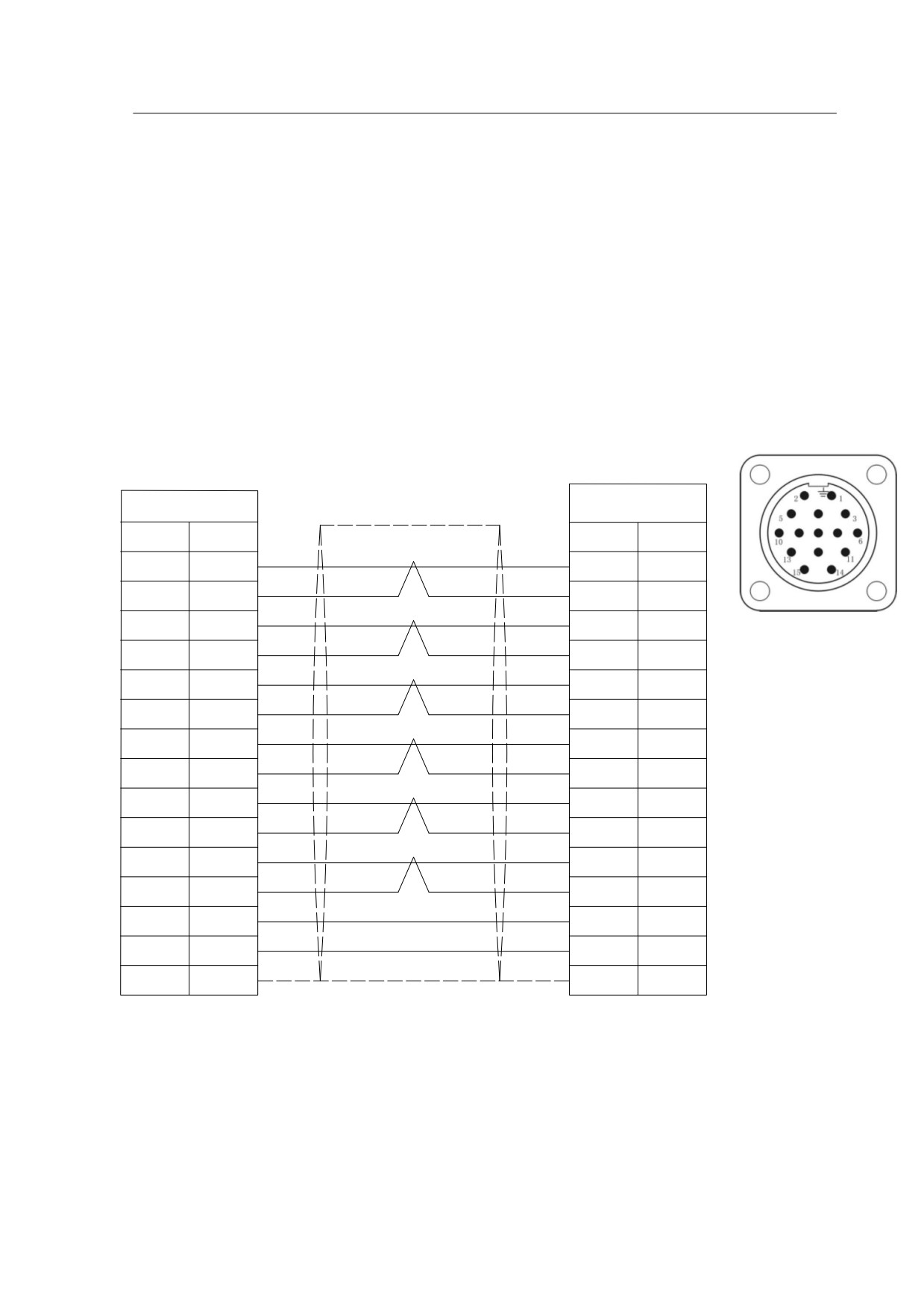
Our HSD2 series servo drive is only applicable with 2500ppr incremental photoelectric
encoder.If you have purchased both our servo drive and motor, then the encoder and
encoder cable and power cable will be included as our agreed standard package. For
special requirement and our users may need to make the encoder cable or modify the
cable, please follow up the following diagram for connections. Please use proper shield
cable if you want to make encoder cable by yourself.
driver
motor
CN2: DB15M
AYD28K15TS
name
pin
pin
name
A+
1
4
A+
A-
9
7
A-
B+
2
5
B+
B-
10
8
B-
Z+
3
6
Z+
Z-
11
9
Z-
U+
14
10
U+
U-
6
13
U-
V+
13
11
V+
V-
5
14
V-
W+
4
12
W+
W-
12
15
W-
+5V
7
2
+5V
0V
8
3
0V
FG
15
1
FG
Diagram
9-1
Connecting diagram HSD2
series drive to motor encoder
79
Chapter 10
System Connection
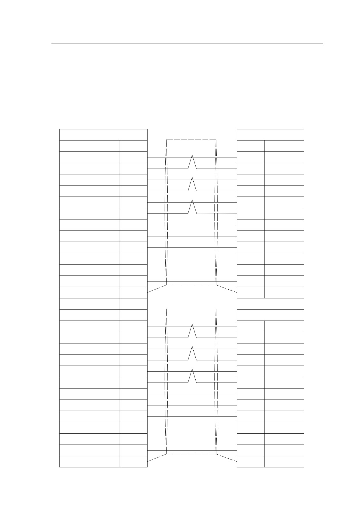
The connection between HSD2 Driver and HNC-602 CNC control system show as
below:
control system
driver
CN5: DB25F
CN2:DB25M
name
pin
pin
name
XCP+
6
26
PULS+
XCP-
18
18
PULS-
XDIR+
7
24
SIGN+
XDIR-
19
25
SIGN-
XZO+
5
2
OZ+
XZO-
17
12
OZ-
ALM
12
21
ALM
0V
13/23
23
DOCOM
INIT
10
14
SON
+24V
11
16
COM+
FG
case
9
PE
CN2: DB25M
ZCP+
3
26
PULS+
ZCP-
15
18
PULS-
ZDIR+
4
24
SIGN+
ZDIR-
16
25
SIGN-
ZZO+
2
2
OZ+
ZZO-
14
12
OZ-
ALM
12
21
ALM
0V
13/23
23
DOCOM
INIT
10
14
SON
+24V
11
16
COM+
FG
case
9
PE
80