HSD2 Series Servo Drive. User Manual - page 2
EE-set
Parameters write: It indicates that all the parameters will be stored
in the EEPROM parameters district, power-off is not going to lose
the saved settings.
EE-rd
Parameters read: you can read the parameters from EEPROM
district, modify the parameters according to your request,
however,when the power goes off, your revised data won’t be
saved.
EE-rs
Parameters restore: you can read the data from the EEPROM
parameter list, do the changes according to your requirement,
perform a write operation to save the revised parameters
permanently.
EE-def
Restore the default parameters: when the parameters are
disordered or changed improperly, you can bring all of the defaults
into the parameter list, and then write the parameters into the
EEPROM. After this operation, you should ensure that the motor
code (PA1) is matching with the motor you are using.
4.6
Speed Trial Run Without Load(Sr--)
You can enable the “Sr” operation mode by set parameter PA4=3. Find the “Sr-” on
the main menu by using the Up and Down key, and then enter the speed trial run
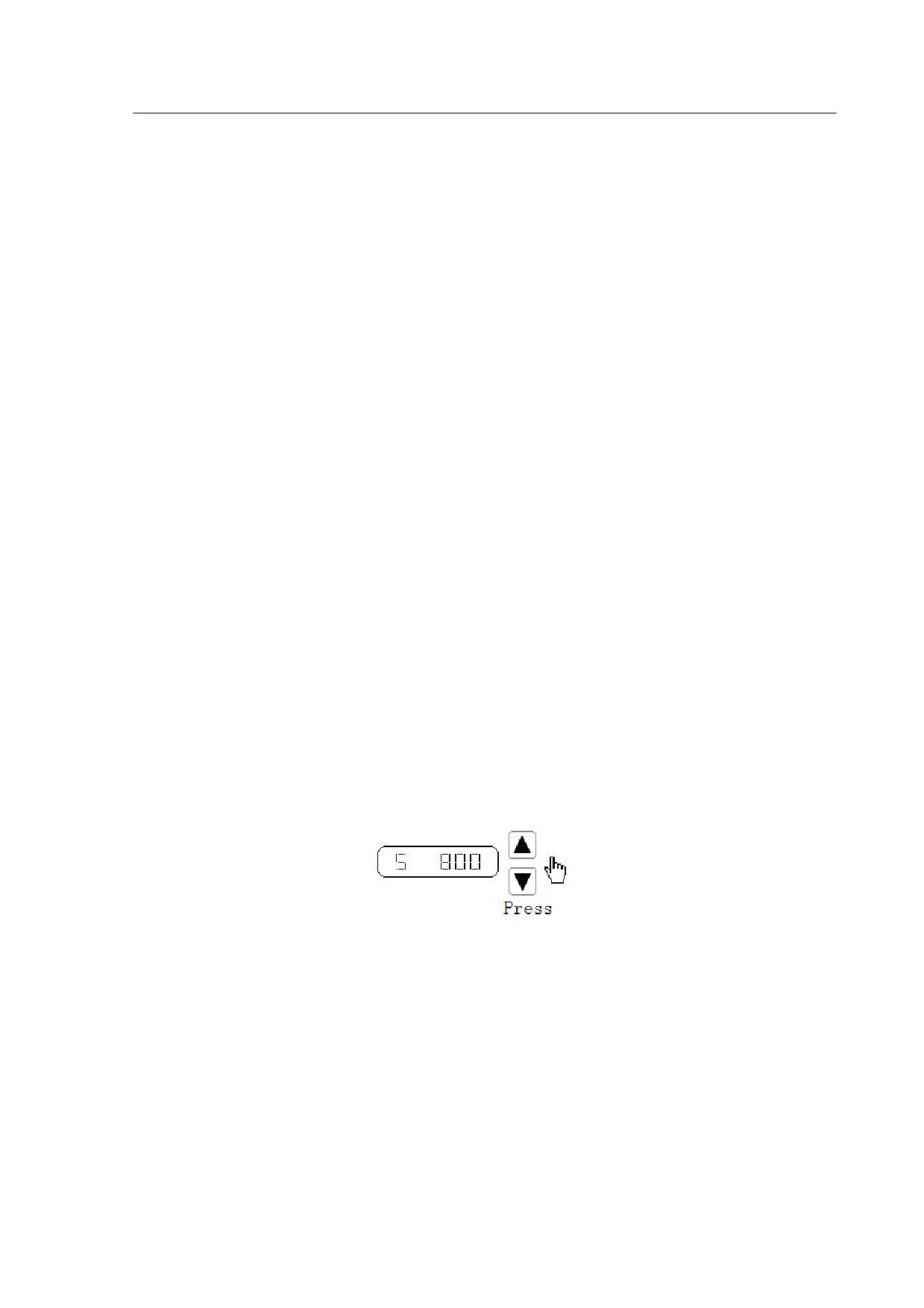
operation interface by pressing the Set key. This mode will display an ”s” and “Sr 0.00”,
the speed unit is r/min, input the speed command by pressing Up or Down key.
Figure 4-6
Speed trial (off load) display
4.7 JOG Trial Run Without Load(Jr--)
You can enable the “Jr” operation mode by set parameter PA4=4 and change the
JOG speed command by setting parameter PA 21. You can find the “Jr-” on the main
menu by using the Up and Down key, and then enter the JOG trial run operation
interface by pressing the Set key. When “J 0.0” is displayed (unit is r/min), press Up or
Down key to jog the motor CCW or CW direction. The motor will rotate according to the
given speed command.
27
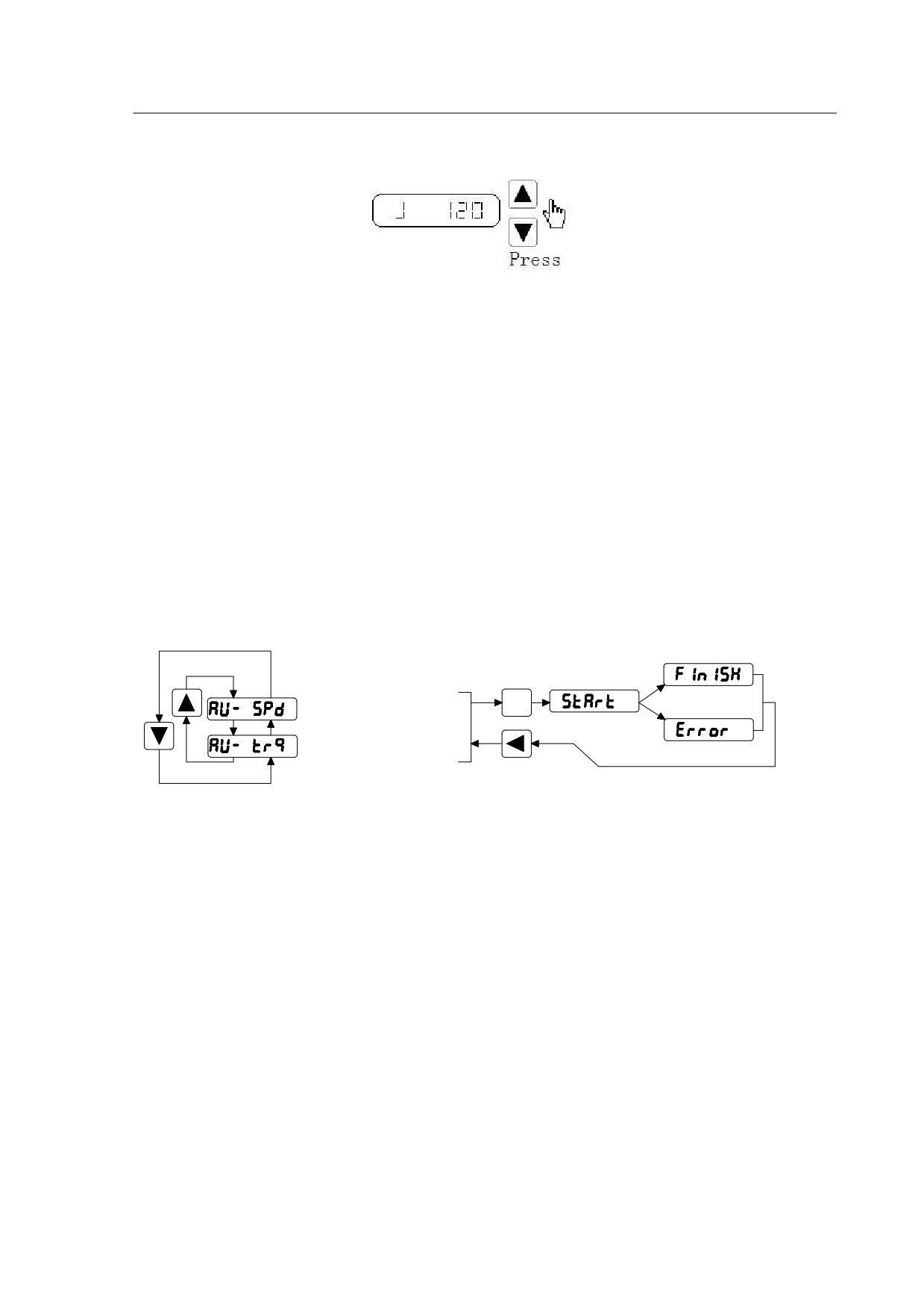
Figure 4-7
Jog trail run without load
4.8 Analog Zero-offset Adjustment (AU)
By performing the following operation, the drive can automatically detect the zero
bias of the analog speed or torque command, and write the value in the parameter
PA45 or PA39. After that, the drive will save the parameter in the EEPROM
automatically. You can find the “AU-” from the main menu by using the Up and Down
key, and then enter the operation interface for Zero-offset adjustment by pressing the
Set key. The AU-SPD correspond to the speed zero-offset adjustment and the AU-trq
correspond to torque zero-offset adjustment. Select the process by Up or Down key,
and then press and hold the Set key for 3 seconds till the LED displays “FINISH”.
Press for
Success
3 seconds
Enter
Analog speed command
Fail
Analog torque command
Figure 4-8
Operations of analog zero-offset adjustment
28
Chapter 5 Trial Run and Tuning
This chapter describes trial run for servo drive and motor, including the trial run
without load and introductions about the operation mode of the drive. Please always
make sure that you perform a trial run without load first, before an on-load
running/operation.
5.1 Inspection Without Load
In order to prevent accidents and avoid any potential damages to the servo drive and
mechanical system, the trial run should be performed without load. Please remove the
load of the servo motor, including coupling on the shaft and accessories so as to avoid
any damage on servo drive or mechanism. This is aiming to avoid the falling off of the
disassembled parts of the motor shaft and indirectly causing the personnel injury or
equipment damage during operation.
Always remember to perform the trial without load first before you connect the drive with
power supply.
Before the trial run (without load), please inspect the following points carefully:
1. Check the drive and motor appearance to see whether or not there is any
obvious damage.
2. Check all the wiring to see if they are correctly connected, especially R, S, T, U, V,
W and PE terminal. The terminals should be connected with the specified cables.
3. Ensure that there are no extra things inside the drive, such as conductive objects
and flammable objects.
4. Confirm that the electromagnetic brake is working normally if brake is required.
5. Please make sure the external voltage level of the servo drive is correct.
6. Make sure that the cable and the mechanical parts are not intertwined, to avoid
wear or pulling phenomenon at the run time.
7. Ensure that the servo drive and motor are well connected to the ground.
Please pay attention to the following notes when you are undertaking the trial run.
1. Please check if there is any abnormal display of the power indicator and LED
display panel.
2. Ensure that all user-defined parameters are being set correctly. The
29

characteristics of different machinery equipment differ from each other, in order to avoid
accident or cause potential damage, do not adjust the parameter abnormally and
change parameter to an excessive value.
3. Make sure that the servo drive is off when you set parameters.
4. Check the vibrations and sound during operation. If the servo motor is vibrating
or there are unusual noises while the motor is running, please contact your local
distributor or manufacturer for further assistance.
5. Please make sure that all the relays are working properly, contact our local
distributor or us directly if there is any abnormal case.
5.1.1 Apply power to the drive
Turn on the control power supply (leave the main power off at the moment), the
LED indicator should be lighted, if there is any alarm displayed on the panel, please
check the wiring.
Next, connect the main power supply, the RUN indicator should be on, if not or
there is any alarm, check the wiring, or replace your drive.
5.1.2 JOG trial run without load
It is very convenient to use JOG trial run without load to test the servo drive and
motor as it doesn’t require an extra wiring. In order to ensure a safe trial run, it is
recommended to set JOG speed at low speed level such as 100r/min. The JOG speed
could be set in the parameter PA21.
1. Parameter settings
Table 5-1
Parameter setting table of the JOG trial run
Parameter
Name
Default
Setting
Description
NO.
Select the operation
PA04
Control Mode
0
4
mode as JOG trial
running mode.
Inhibit
Drive
Ignore
the
drive
PA20
1
1
Function
prohibition
Speed
command
PA21
JOG speed
120
100
selection
Reduce
the
PA40
Acceleration Time
0
Opportune
acceleration
Shock.
30
Reduce
the
PA41
Deceleration Time
0
Opportune
deceleration
Shock.
Enable the drive without
PA53
Enabled Word 1
1
1
the external force
2. Operation
Step 1: Set the parameter PA53=0001, the servo drive is activated, indicator Power
and Run is on light, both the drive and motor are in a zero speed running status.
Step 2: Set parameter PA21 as JOG speed. After the desired JOG speed is set,
and then press the Set key, the speed will be written into the control software.
Step 3: Enter the JOG operation interface by using the digital keypad, and the
digital LED display should be displayed as the following:
J
0.0
(r/min)
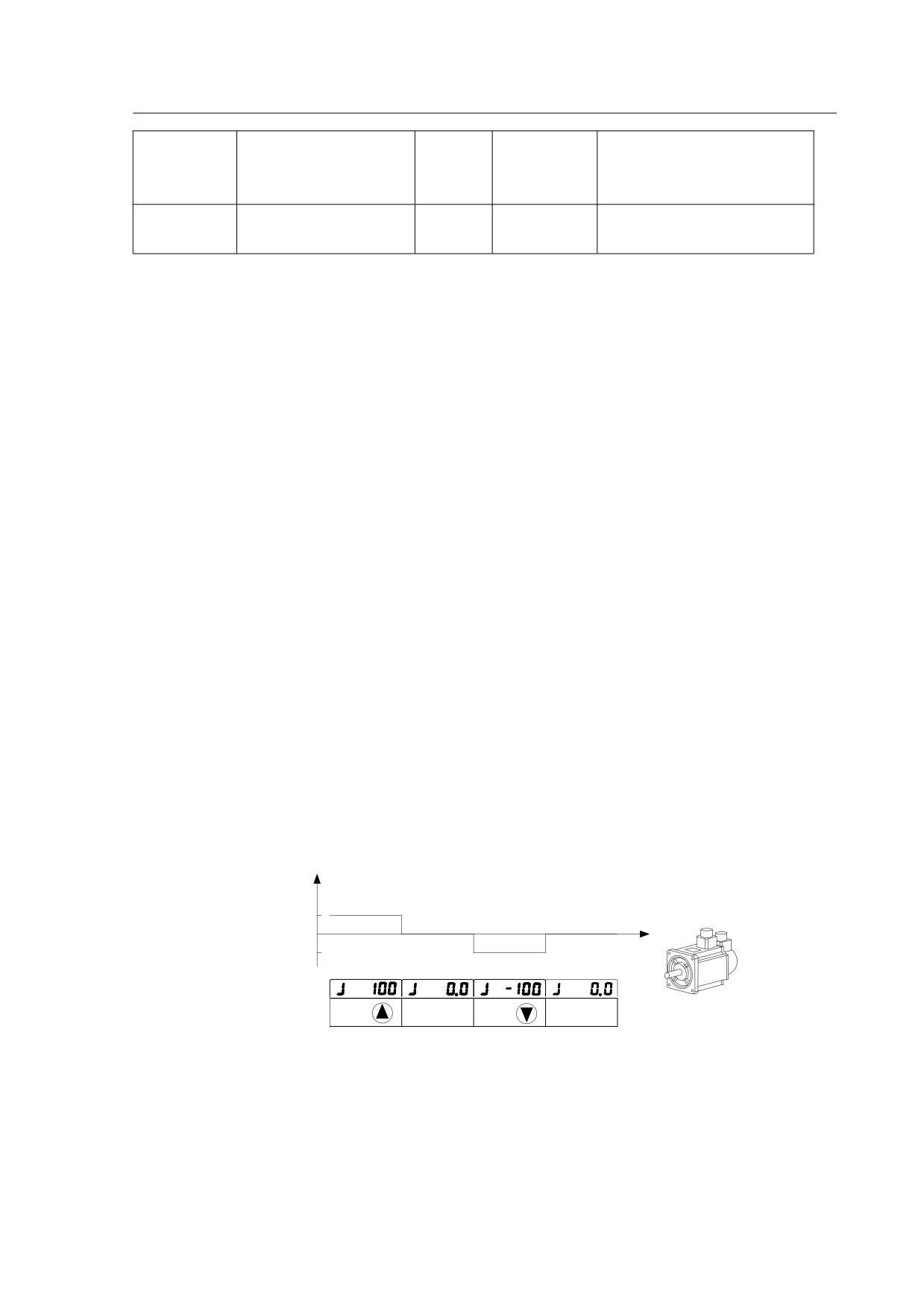
Step 4: Press the Up key and the servo motor will run in CCW direction. After
releasing Up key, the motor will stop running.
Step 5: Press the Down key and the servo motor will run in CW direction. After
releasing Down key, the motor will stop running.
Step 6: Press Return key, the drive exits JOG operation mode.
CCW and CW definition.
CCW ( ): Face the servo motor shaft, CCW is running in the counterclockwise
direction.
CW (): Face the servo motor shaft, CW is running in clockwise direction.
Sr
100
0
-100
t
Display:
Operation:
Press
Lossen
Press
Lossen
Figure 5-1
JOG trial run without load
5.1.3 Speed trial run without load
Before you perform this operation, please ensure all the parts and basement are
properly tightened and secured with the servo drive and motor. During the high speed
31
running, any unsecured parts can cause malfunction and personnel injury.
1. Parameter setting
Table 5-2
Parameters for the speed trial run
Parameter
Name
Default
Setting
Description
Select the operation mode
PA04
Control mode
0
3
as speed trial running control
mode.
Inhibit Drive
PA20
1
1
Ignore the drive prohibition
Function
Enable the drive without the
PA53
Control word 1
1
1
external signal
2. Operation
Step 1: Set the parameter PA53=1the servo drive is activated, indicator Power and
Run is on light, both the drive and motor are in a zero speed running status.
Step 2: Set parameter PA04 =3, choose the speed trial running mode as the current
mode.
Step 3: Enter the speed trail run operation interface by pressing the UP and DOWN
key, the minimum given vale is 0.1r/min.Use the Up or Down key to select the “Sr”
mode on the main menu, and the press the Set key to enter the operation interface for
the speed trial running. And the LED display should be shown as the following:
S
0.0
(r/min)
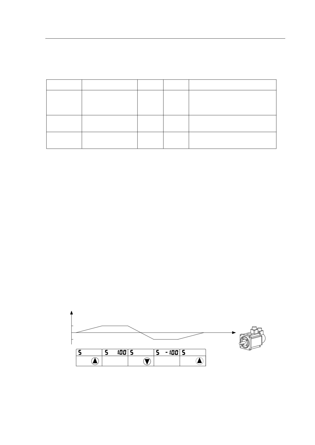
Step 4: By pressing the UP and DOWN key, you can change the running speed as
well as the running directions (CCW, and CW).
Sr
100
0
-100
t
Display:
Increase
Decrease
Increase
Press
Lossen
Press
Press
Lossen
Operation:
Figure 5-2 Speed trial run
32
5.2 Position Control Mode
The position control mode is usually used for the applications requiring precision
positioning, i.e, industry positioning machine. Before position trial run, please carry out
the following inspections:
1. Ensure that all wiring is correct and wiring terminals of the servo drive and motor
are correctly insulated.
2. Ensure all the parts and basement are properly tightened and secured with the
servo drive and motor. During the high speed running, any unsecured parts can cause
malfunction and personnel injury.
5.2.1 Simple position control system
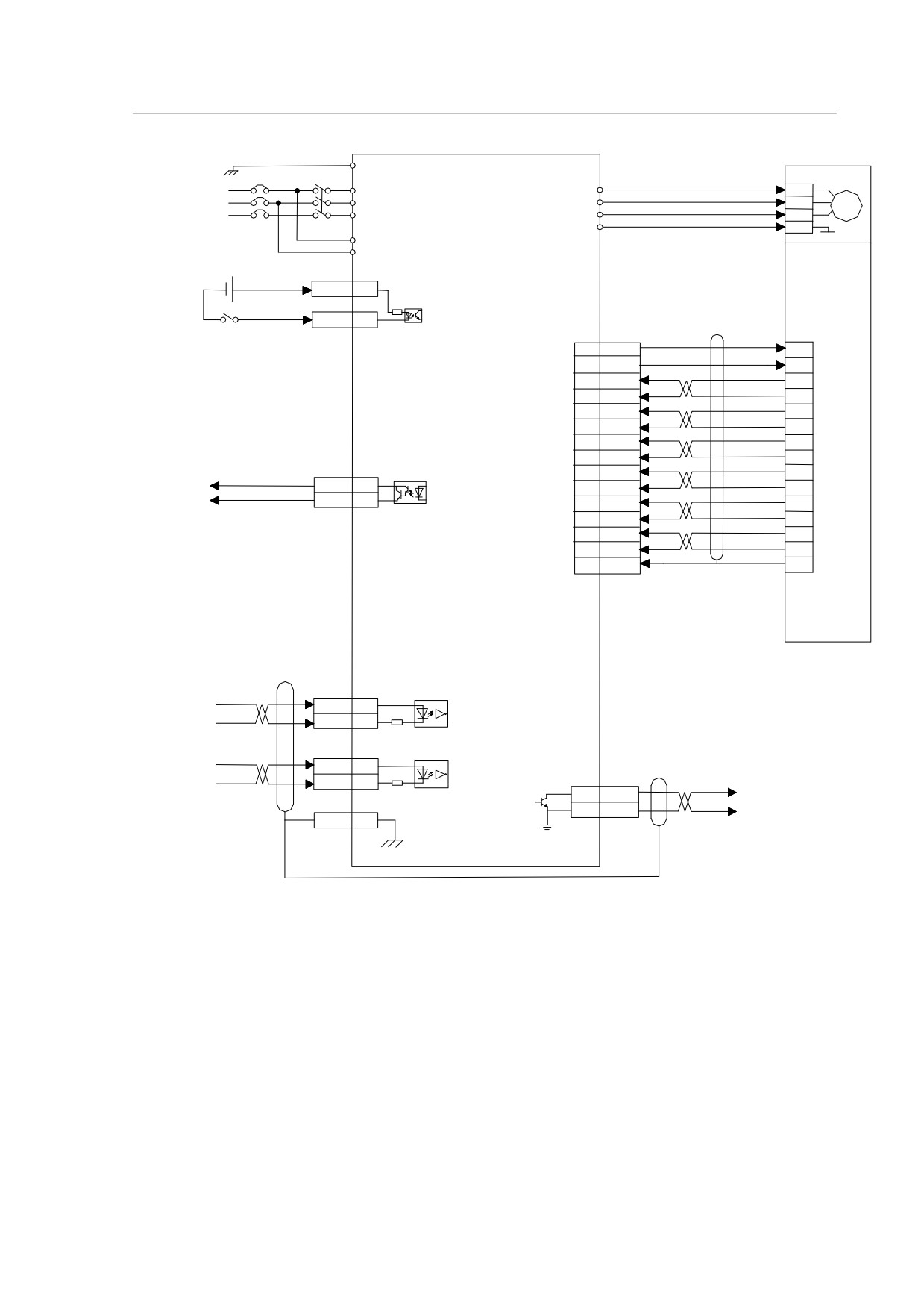
A simple position control system only requires two sets of position pulse command
signals, drive enable signal, prohibited drive signal, servo ready and servo alarm output
signals. Please refer to the wiring from the below Diagram 5-3.
33
PE
MOTOR
R
U
2
3P AC 220V
S
V
3
Driver
W
4
T
NFB
MC
PE
1
r
t
CN2
DC 12~24V
COM+
16
4.7k
Enable
SON
14
CN1
7
5V
2
8
0V
3
1
A+
4
9
A-
7
2
B+
5
26LS32
10
B-
8
RX
3
Z+
6
11
Z-
9
ENCODER
CN2
14
U+
10
ALM
21
6
U-
Alarm
13
DOCOM
23
13
V+
11
5
V-
14
4
W+
12
12
W-
15
15
PE
1
CN2
PULS+
26
PULS
PULS-
18
220
SIGN+
24
SIGN
SIGN-
25
220
4
CZ
Z
Z output
6
GND
FG
9
FG
Diagram5-3
Wiring for the simple position control system
Note: In section 3.6.1, you can find the detailed wiring diagram for the position
control system.
34
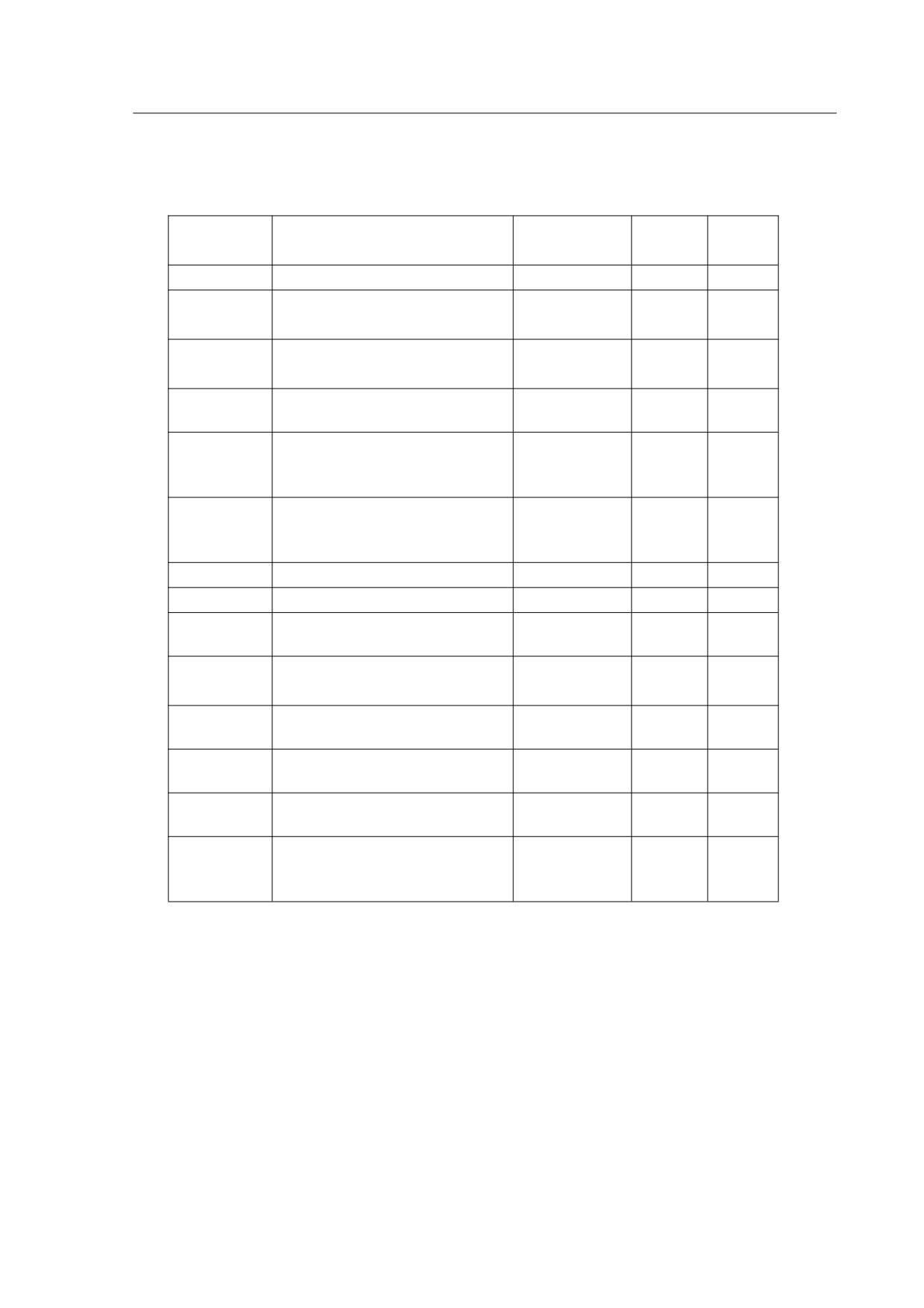
5.2.2 Parameters for the position control
Table 5-3
Parameters for the position control mode
Parameter
Name
Value range
default
unit
NO.
PA04
Control mode
0~-5
0
Proportional Position Loop
PA09
1~1000
130
Hz
Gain
Position Feed Forward
PA10
0~100
0
%
Gain
Filter time Constant of
PA11
0~1000
0
ms
PA10
Pulse command Electronic
PA12
Gear Ratio
1~30000
1
(Numerator) N1
Pulse command Electronic
PA13
Gear Ratio
1~30000
1
(Denominator) M1
PA14
External Pulse Input Type
0~2
0
PA15
Direction of external pulse
0~1
0
Positioning Completion
PA16
0~30000
20
range
100
PA17
Position error Range
0~30000
400
pulse
Position Error
PA18
0~1
0
Invalid control bit range
Position command Smooth
PA19
0~30000
0
0.1Ms
filter
Inhibit Drive Function
PA20
0~1
0
Selection
Digital Input Terminals
PA53
Function Selection /
0~1
1
Enabled Word 1
35
Pulse command input type
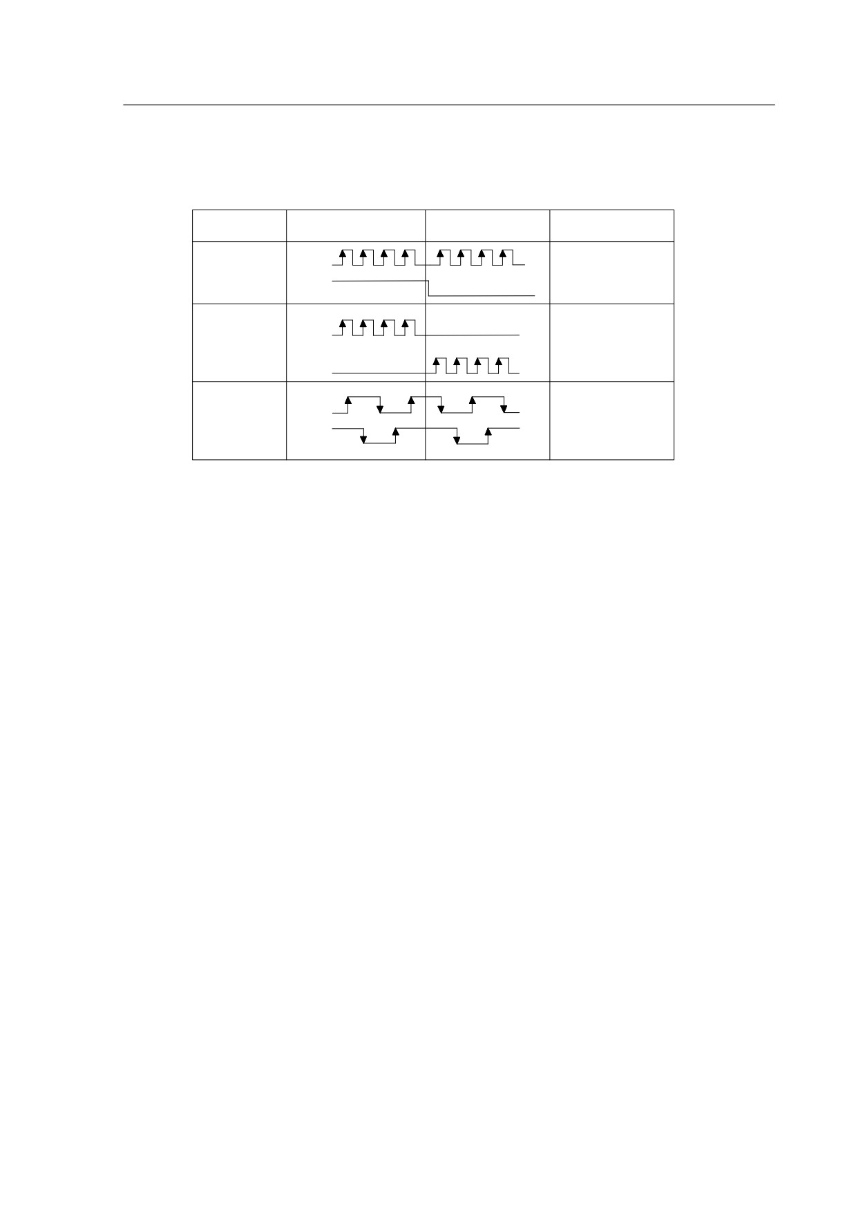
Table 5-4
Type and waveform of position command input type
Pulse Type
Forward
Reverse
PA14
Pulse
PULS
+
0
Direction
SIGN
CCW
PULS
+
1
CW
SIGN
AB
PULS
Phase
2
SIGN
Pulse
The host controller uses pulse command to control motor running and positioning
via servo drive, in general, there are three different types of pulse outputting from the
host controller: Pulse+ direction; CCW+CW;AB phase pulse..
The above three types are applicable with HSD2 series drive, you can select the
required mode by setting parameter PA14.The detailed descriptions, please refer to the
Table 5-4, the arrows indicate pulse counting, PA15 is used to change the pulse count
direction.
Position pulse inputs through the terminals PULSE+(26) , PULSE-(18) , SIGN+(24),
SIGN-(25) of CN2 connector, please refer to the detailed definition and description from
section 3.4
Filter for position control
The filter is designed to smooth the motion command. You can set parameter PA19
to to achieve pulse filtering under the following circumstances: when the host controller
doesn’t have accelerate or decelerate function, electronic gear ratio set value being too
high; system load inertia being high or command frequency value is low. By using the
pulse filter, you can have a more stable and smooth pulse frequency, avoid position
command lose, however, this performance will delay command reactions. When
PA19=0,it means the filter is being disabled. This parameter indicates the time for
position frequency varies from 0-63% of the external pulse frequency. The pre and after
filtering diagram comparison, please refer to the following Diagram 5-4.
36
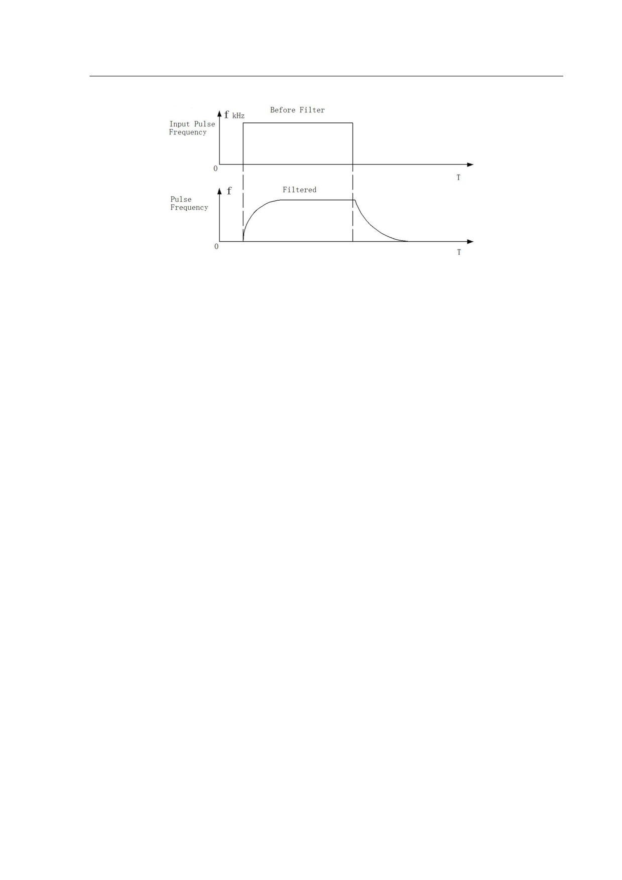
Diagram5-4 Comparison waveform between Pre and after filtering
5.2.3 Electronic gear ratio
Electronic gear provides simple ratio change of travel distance. The high electronic
gear ratio would cause the position command to be the stepped command.
Please follow the below rules for setting:
N1: Numerator of the electronic gear ratio (PA12 )
M1: Denominator of the electronic gear ratio (PA13 )
P1: Number of pulses corresponding to 1mm in the host controller
F2: Number of encoder pulses per circle
S1: Screw pitch of the mechanical transmission (mm)
F1: Number of pulses required by actual moving distance 1mm.
F1=N1*P1/M1 (pulses / mm)
F1=F2/S1
(pulses / mm) for actual moving distance without gearbox
Therefore the electronic gear ratio N1/M1 is equal to F2/(S1*P1).
For example, if P1 of the host is 1000 pulses/mm, F2 of the H series servo drive is
10000, S1 of the screw is 6mm, the electronic gear ratio N1/M1=10000/(1000*6)=5/3.
So you can set the parameter PA12 (N1)=5 and the PA13 ( M1 )=3.
If there is a gearbox between ball screw and motor, the ratio of the gearbox is
N2/M2;
N2: rotation number of the motor
M2: rotation number of the ball screw
F1=N1*P1/M1
(pulses / mm) for host controller
F1=F2*N2/(S1*M2)
( pulses / mm ) for actual moving distance with gearbox
Therefore the electronic gear ratio N1/M1 equals to F2*N2/(S1*P1*M2).
For the above-mentioned example, if the ratio of the gearbox is N2/M2=5/3.
37
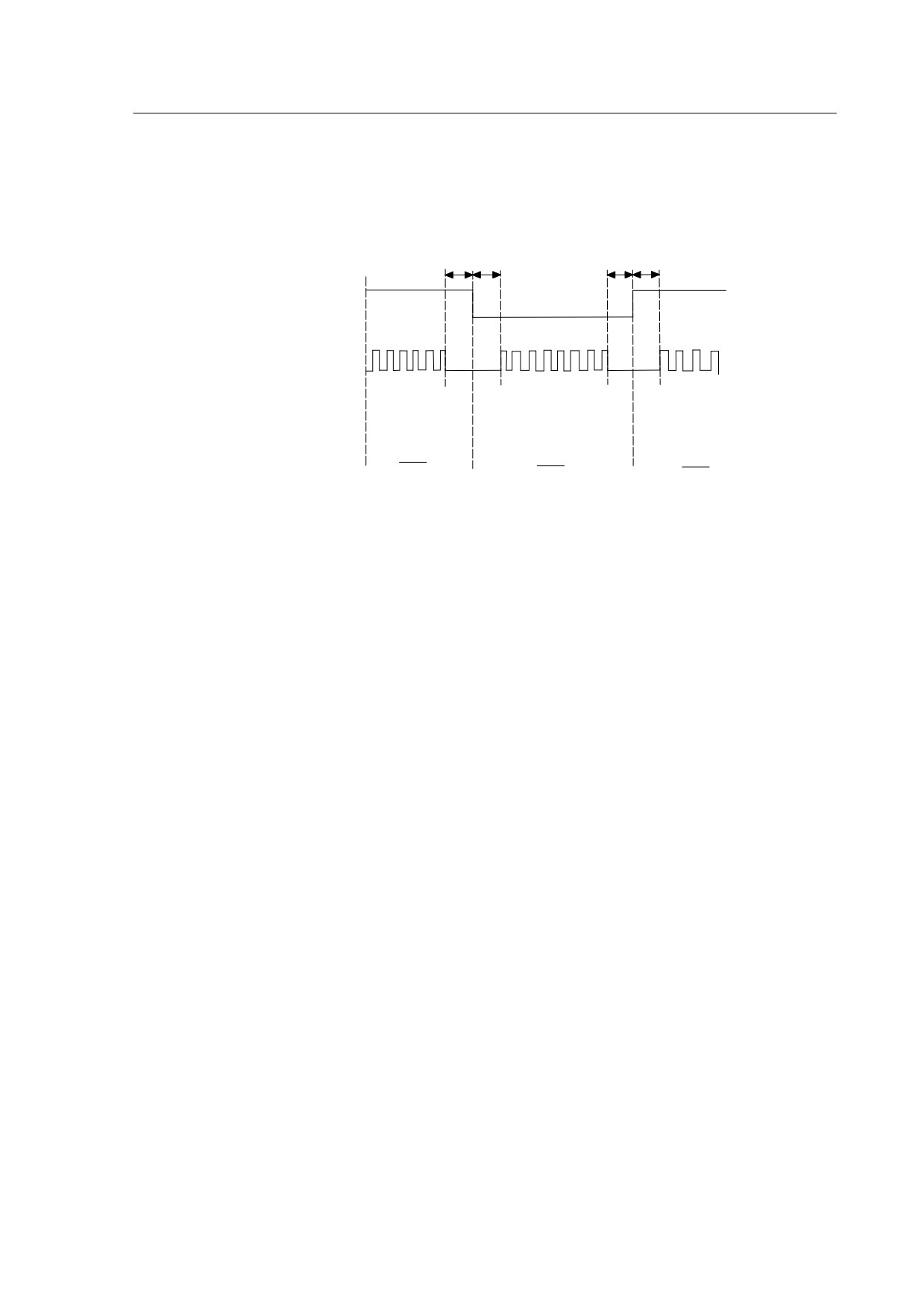
According to the formula, the electronic gear ratio N2/M2=10000*5/(1000*6*3)=25/9. So
you should set the parameter PA12 (N2) =25 and the PA13 (M2) =9 for the mechanical
transmission system with a gearbox.
t1
t2
t3
t4
INH signal
ON
OFF
OFF
Pulse command input
1st ratio
2nd ratio
1st ratio
Electronic gear ratio
PA12
PA52
PA12
PA13
PA13
PA13
t1,t2,t3,t4>10mS
Diagram5-5 Dynamic electronic gear ratio
Note:HSD2 series servo drive provides two sets of dynamic electronic gear ratio.
The second numerator of the electronic gear ratio is set in the parameter PA 52, and
denominator is same as the first one (PA13). When the PA51 equal to 1, the function of
the dynamic electronic gear is enabled and the signal connected to pin-15 of the I/O
port CN2 could control the switching of the electronic gear. When the level of the signal
is low, the servo drive chooses the second electronic gear ratio PA52/PA13.
38

5.2.4 Position control gain
Before you set the position control unit, please complete the setting of speed
control unit manually since the speed loop is included in the position loop. After this
operation, you can then adjust the position loop gain PA09 and position feed forward
gain PA10 accordingly.
Table 5-5
The parameters for the position control gain
Parameter
Value
Name
Description
Defaults
NO.
range
Increase the gain so
as to enhance the
PA-09
Position control gain
0~1000
50
response bandwidth
of position loop.
Minimize the
PA-10
Position feed forward gain
deviation of phase
0~100
0
delay
Smooth the
accelerate and
PA-11
Feed forward smooth filter
0~1000
0
decelerate ,reduce
overshoot.
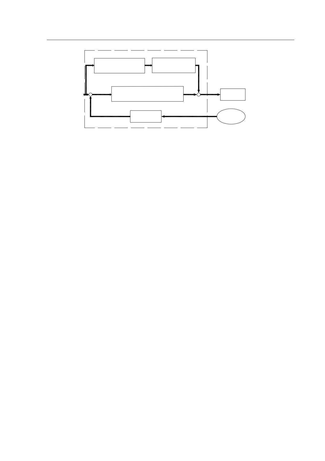
Because the positional control loop includes the speed control loop, the position
loop bandwidth can be restricted by the one of the speed loop. It is recommended that
the speed loop bandwidth should be at least four times faster than the position loop
bandwidth. This means that the setting value of the proportional speed loop gain PA05
should be at least four times more than position control gain PA09.
The position loop bandwidth cannot exceed the speed loop bandwidth. It is
suggested that fp ≤ fv/4.
fv: response bandwidth of speed loop (Hz).
Fp: response bandwidth of position loop(Hz)
KPP (PA09)= 2 ×π× fp
For example, the desired position loop bandwidth is 40 Hz.
Then PA09=2*π*40=251 rad/s
39
Position feed
Smooth Constant
forward gain PA-10
PA-11
+
Position loop
+
Speed
+
proportional gain PA09
Command
-
Position
Encoder
Counter
Diagram5-6 Flowchart of the position control loop
Increase the value of position loop gain can enhance the position response and
reduce position error. If the set value is too high, it may cause vibration and noise.
If the position command is being transmitted smoothly, increasing the gain value can
reduce the position error. However, if the position command is not transmitted smoothly,
decreasing the gain value can tackle the problem of mechanical vibration.
When the value of proportional gain, (KPP set value) is too big, the response
bandwidth of position loop will be increased and diminish the phase margin. And the
motor rotor rotates back and forth with vibration. Thus, KPP has to be decreased until
the rotor stops vibrating. When the external torque interrupts, the over low KPP (PA09)
cannot meet the demand of position deviation. In this situation, adjusting parameter
PA10 can effectively reduce the position error.
5.3 Gain Adjustment
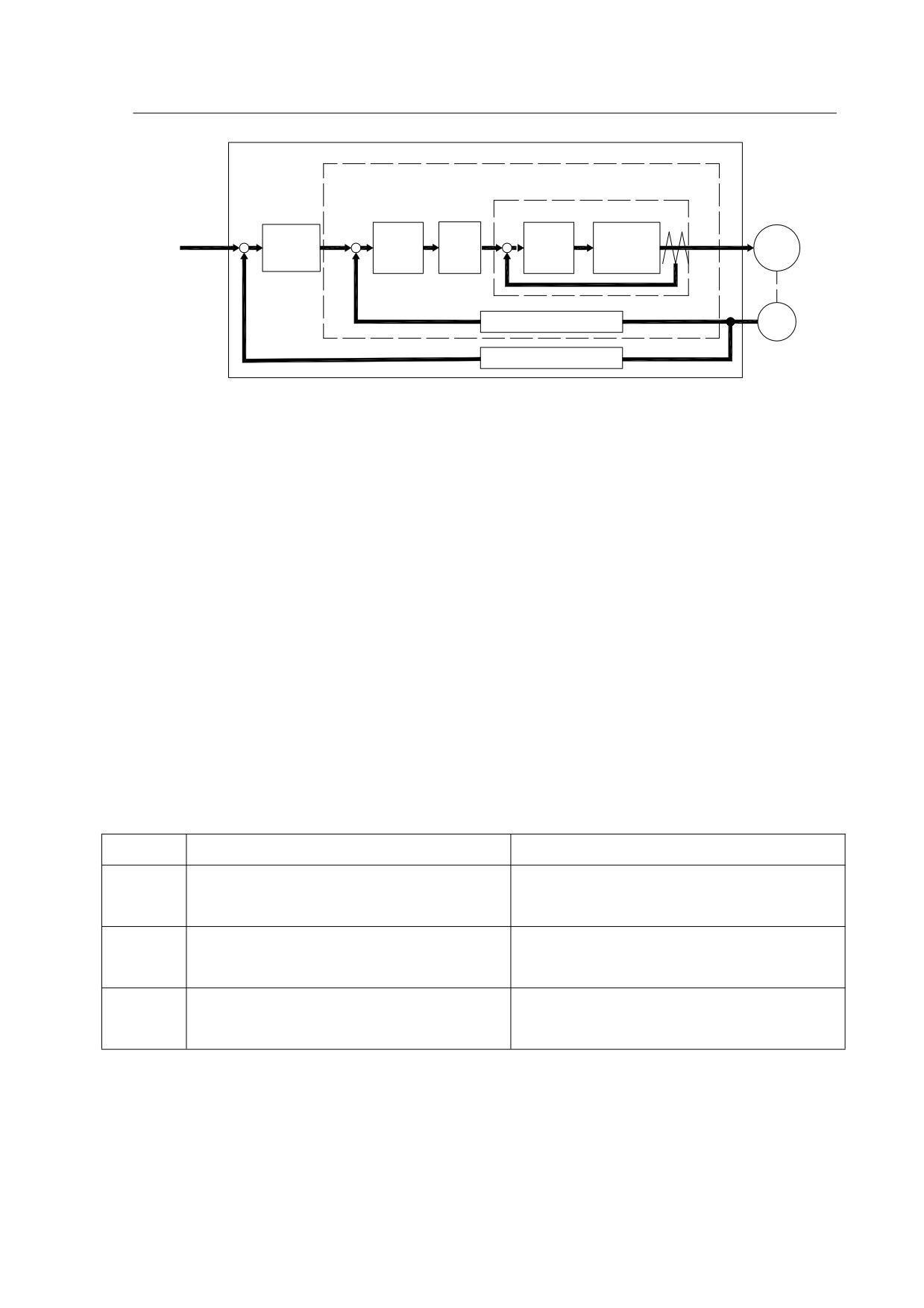
Servo drive has three control loops: position control loop, speed control loop and
current control loop. Please refer to the below Diagram 5-7 for detailed explanation.
The inner control loop bandwidth should always be higher than the outer control
loop, otherwise it will cause motor rotor running back and forth with vibration and noise,
affect the actual performance.
Therefore, having correct selection of response bandwidth for each control loop is
very crucial. Generally speaking, the current loop has the highest response bandwidth
while the position loop has the lowest.
The response bandwidth of the current loop is decided by the system itself, users
can’t modify this value by themselves. Please set and match the bandwidths for both
speed loop and position loop properly through adjusting.
40
Position Control Loop
Speed Control Loop
Current Control Loop
Position
Speed
Current
Power
Position
+
+
+
Control
Control
Filter
Control
Conversion
Motor
Command
-
Block
Block
-
Block
Block
-
Speed Detection
Encoder
Position Detection
Diagram 5-7
Servo closed-loop control
5.3.1 Steps for gain adjustment
Since the motor load inertia, stiffness, damp ratio differ from the environment or
application changes, the system default settings are not good enough to ensure a
perfect response and cover all the circumstances. Therefore, adjusting the speed and
position respond bandwidth according to each application is quite necessary to achieve
a good performance from the servo system.
As for the whole system, when you change one of the parameters, the relevant
ones also need to be modified accordingly, please do not set some excessive values
and follow the below operation rules respectively:
Table 5-6 steps and rules for parameters setting
Reduce vibration or overshoot
Increase response speed
Decrease the proportional position
Increase the proportional speed
Step 1
control gain PA9
control gain PA9
Increase the integral time of the
Decrease the integral time of the
Step 2
speed control PA6
speed control PA6
Decrease the proportional speed
Increase the proportional position
Step 3
control gain PA5
control gain PA9
5.3.2 Gain adjustment for speed control loop
You can adjust the relative speed control loop gain according to the following steps:
Step 1: Increase the integral time of the speed control loop PA6
41
Step 2: Gradually increase the value of the proportional speed control loop gain
PA5 setting without causing major vibration or noise
,if this does occur, please
decrease the gain setting value properly.
Step 3: Gradually decrease the integral time of the speed control loop PA6 until the
resonance occurs, and then increase the setting value to eliminate the vibration.
Step 4: If the mechanical system resonates at a certain point, it’s impossible to get
a very good system response performance. In this case, please adjust the torque value
PA22 for the low-pass filter to suppress the resonance, repeat the above steps to
achieve a better response characteristic for the position and speed control loop.
5.3.3 Gain adjustment for position control loop
If the inertia of the machinery and conditions of applications is too high, and it
creates system resonance, you can adjust the relative parameters according to the
following steps:
Step 1: Increase the integral time of the speed control loop PA6
Step 2: Gradually increase the value of the proportional speed control loop gain
PA5 setting without causing major vibration or noise
,if this does occur, please
decrease the gain setting value properly.
Step 3: Gradually decrease the integral time of the speed control loop PA6 until the
resonance occurs, and then increase the setting value to eliminate the vibration.
Step 4: Gradually increase the value of proportional position loop gain until the
resonance occurs, and then decrease the setting value to eliminate the vibration.
Step 5: If want to shorten position control time and minimise position error, you can
adjust position feed forward gain PA10 and PA11 (the smooth constant of feed forward
gain) to achieve it.
Step 6: If the mechanical system resonates at a certain point, it’s impossible to get
a very good system response performance. In this case, please adjust the torque value
PA7 for the low-pass filter to suppress the resonance, repeat the above steps to
achieve a better response characteristic for the position and speed control loop.
5.4 Electromagnetic Brake
When operating brake via servo drive, if the digital output BRK is set to off, it
42

indicates that the electromagnetic brake is disabled and motor is locked. If the digital
output BRK is set to ON, it indicates electromagnetic brake is enabled and motor can be
operated. The electromagnetic brake is usually applied in Z-axis to reduce the large
energy generated from servo motor. In order to avoid the brake error, it must be on
when the servo drive if off. The brake has to be activated before the motor stops
running (Servo OFF). The brake has to be released after Servo ON. Otherwise, it would
become the load of the motor and may damage the brake.
If the brakes is working during the process of acceleration or constant speed, the
servo drive needs to generate more current to resist the force of brake and it may cause
the alarm of overload warning.
5.4.1 Parameters of electromagnetic brake
The on delay time of the electromagnetic brake is set within the servo drive, except
this there are three parameters about the off delay time (speed) of the electromagnetic
brake. The users can use these three parameters to set the off delay time of
electromagnetic brake.
Table 5-7
Parameters for the electromagnetic brake
Parameter
Value
Applic
Name
Defaults
Units
NO.
range
able
Motion delay time of
All
PA47
electromagnetic brake when
0~200
0
10ms
motor is still
Motion delay time of
All
PA48
electromagnetic brake when
0~200
50
10ms
motor is running
Motion speed for
All
PA49
electromagnetic relay when the
0~3000
100
r/min
motor is running.
43
5.4.2 Wiring of electromagnetic brake
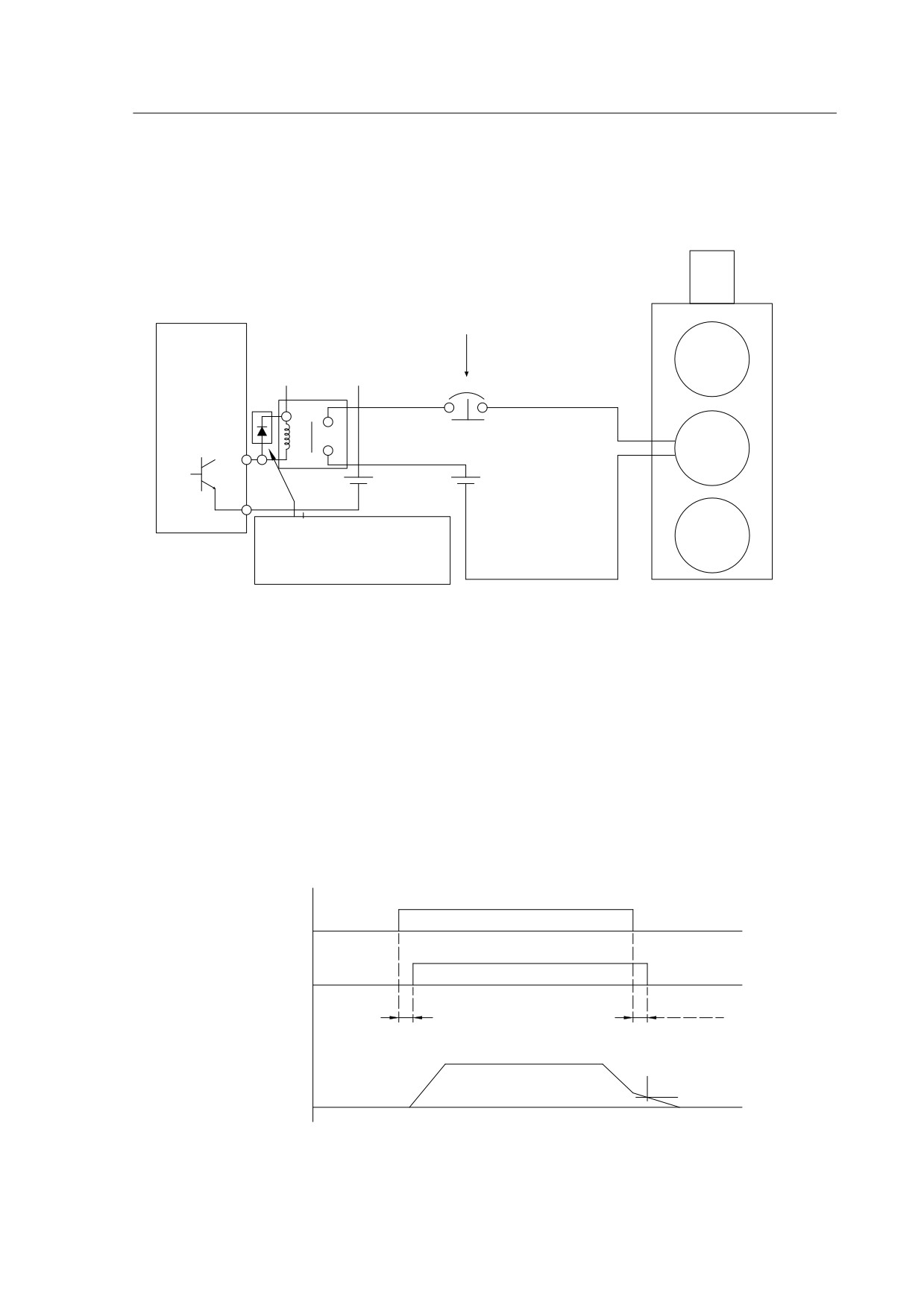
Wiring of the electromagnetic brake is shown in the below Diagram 5-8.
When emergency stop signal
is activated,this circuit
breaker will be enabled.
Servo drive
Do not connect
Motor
VDD and COM+
BRK+
Brake
For brake
Relay
VDD
DC24V
BRK-
DC24V
Ensure the polarity of
Encoder
Diode is correct or it
may damage the drive
Diagram5-8
Diagram for electromagnetic brake
The BRK signal controls the brake operation. The VDD DC24V power supply
supplied externally should be used to power the relay coil. When BRK is on, the motor
brake is activated. Please note the coil of the brake has no polarity, while the diode has
polarity, please ensure the polarity of the diode is correctly matched or it may cause
damages to the drive. Power supply for brake is DC24V. Never use brake power and
control power (VDD) at the same time.
Timing diagram of electromagnetic brake control:
ON
SON Signal
OFF
OFF
(CN2-24 input)
ON
BRK Signal
OFF
OFF
(CN2-30 input)
T1
T2(PA-49)
Motor Speed
PA-48
Diagram5-9 Timing diagram of brake control
44

BRK output timing explanation:
1. when servo off ( when DI SON is not activated), the BRK output goes off
(electromagnetic brake is locked ) after the delay time set by PA48 reached and the
motor speed is still higher than the setting value of PA49.
2. when servo off ( when DI SON is not activated), the BRK output goes off
(electromagnetic brake is locked ) if the delay time set by PA48 has not reached but the
motor speed is still lower than the setting value of PA49.
5.5 Timing
5.5.1 Timing for power supply
Step 1. Control power supply should be turned on earlier than the main power, or
simultaneously.
Step 2. When the main power is turned on, it delays for about 1.2s.The servo SYDY
signal is ready, then the servo drive is able to receive enable signal (SON) from host
controller. When the drive detects SON signal, main circuit can be activated, the motor
is now in a operational status. If the serve drive detects the invalid SON signal or there
is any alarm, main circuit will be disabled and the motor will be in a zero-speed status.
Step 3. Please try to avoid switching the system power on and off too often.
Control power
POWER ON
OFF
r,t
< 0.5ms
Control power
ON
OFF
(+5V)
Main Power Supply
OFF
Power ON
L1、L2、L3
< 1.2ms
Servo Ready Output
ON
OFF
(DO:RDY)
> 5ms
Servo Enable Signal
ON
OFF
(DI:SON)
< 5ms
Servo Output Power
OFF
ON
U,V,W terminal
BRK signal
OFF
ON
( DO )
Diagram5-10
Timing flowchart of control power and main power
45
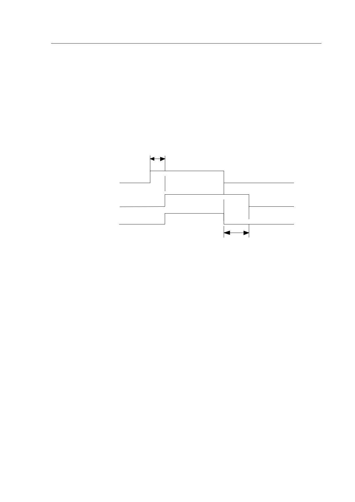
Note:Even if the host controller output the SON signal before the SRDY signal of
the drive, the servo drive couldn’t receive the SON until the SRDY signal is ON for 5 ms.
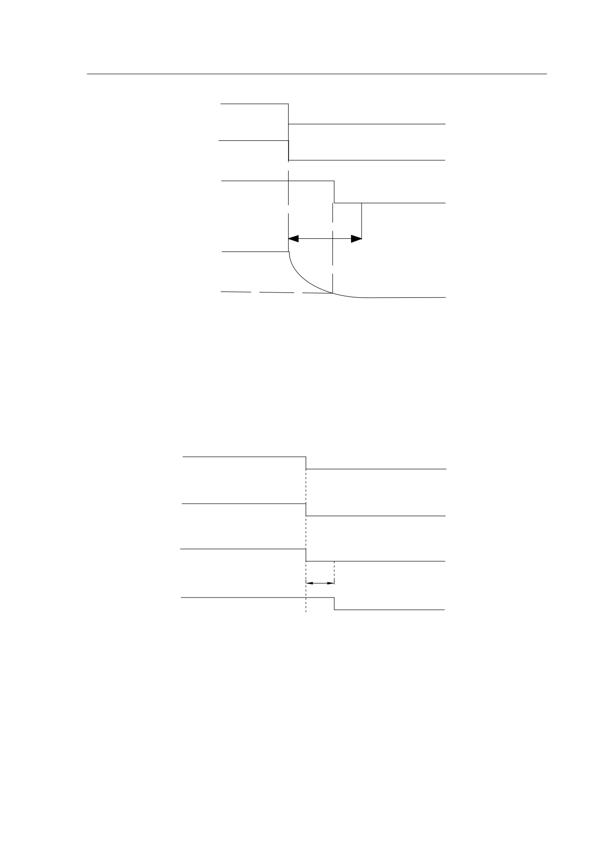
5.5.2 Timing for enable operation
1. Enable operation ON/OFF timing for standstill motor
When the motor is still, if the SON is OFF, the main circuit continues to work to hold
the position, the brake is going through the stage of OFF-ON-OFF, wait for a
while(PA47 setting value) and disable the power supply for the motor.
<10ms
Servo Enable
Signal(SON)
OFF
Servo ON
OFF
Motor Current
OFF
OFF
Signal
ON (motor drived)
OFF
ON (motor free)
OFF
BRK Signal
Set By
PA47
Diagram 5-11
Enable operation timing flowchart when motor is still
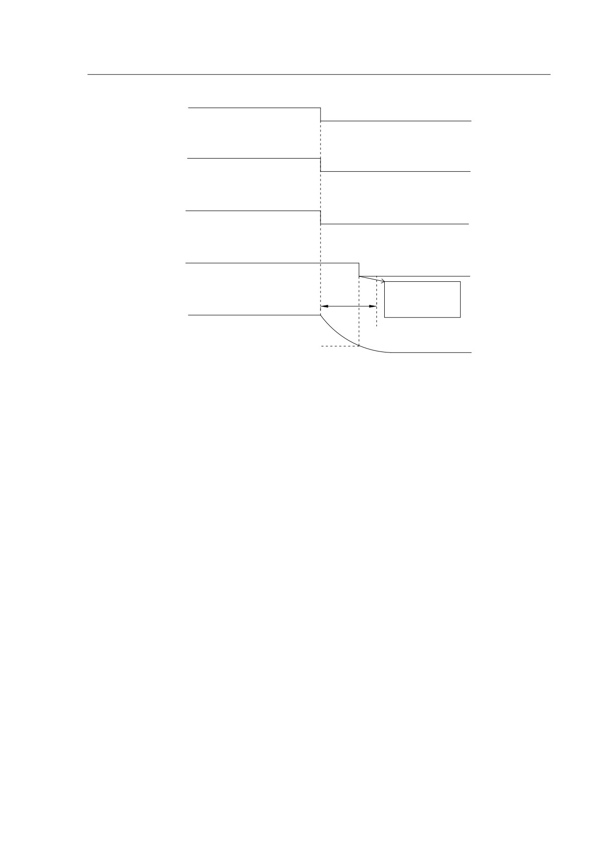
2. Enable operation ON/OFF timing when the motor is running
When the motor is running, if the SON is off, the main circuit of the drive will be
disabled and the brake continues to be ON before it turns OFF because of the delay. In
this way, we can avoid the potential damage to the brake when the motor is still running
at a very high speed. The actual delay timing is decided either by parameter PA48 or
the time for the motor to be slowed down to the set value of PA49, the lower one of the
two numbers is the actual delay time.
46
Servo Enable
Signal(SON)
ON
OFF
Motor Current
ON
Power OFF
Signal
( motor drived )
OFF
ON (motor
free)
BRK Signal
PA48
Motor speed
(r/min)
PA49
0r/min
Diagram5-12
Disable operation timing flowchart when motor is running
5.5.3 Servo enable & servo alarm flowchart
1.servo enable & servo alarm timing flowchart when the motor is in static status:
Servo
OFF(error occur)
ON(no alarm)
Alarm
Enable
OFF
ON
servo
Motor Current
Power off
Power on
Status
PA47
Brake
OFF(Brake is working)
ON(Brake
(BRKsignal)
released)
Note: when the motor is in a static status, an error occurs, it will trigger the servo alarm,
servo enable OFF very instantly, this will cut off the power at the same time.If you want
the brake to work instantly,you need to set PA47=0.
servo enable & servo alarm timing flowchart when the motor is in the running status.
47
Servo
OFF(error occur)
ON(no alrm)
Alarm
Enable servo
OFF
ON
motor current
Power off
Power
status
on
Brake
OFF(Brake is working)
(BRK
ON(Brake
reach PA49 set
signal)
release)
speed or PA48 set
PA48
time
Motor speed
r/min
PA49 set speed
Note: when the motor is in a running status and there is an error and it triggered the
servo alarm, servo enable will be off very instantly, power will be cut off at the same
time.The motor may be running at a high speed when the alarm triggers, in this case, if
the brake is enabled to stop the motor at a high speed, it may damage the
brake.Therefore, we have PA48 and PA49 two parameters to avoid the potential
damage.PA48 is the brake response delay time, PA49 is the set motor speed for the
brake to enable.The brake will work if one of these parameters reached it’s set value.
If the motor is applied on the vertical axis of the equipment/machine, and it doesn’t
allow any degree of free-fall of the motor, set PA48=0,and the brake will be working
straight after the alarm triggered.
If the applied equipment can allow a certain distance of free-fall for the motor, you can
set proper values for PA48 & PA49, the brake will be enabled until the motor speed
slows down to a certain degree(PA49 set value).During the speed slowdown process,
the power is in OFF status for the servo, the load inertia slows the motor down in this
case. If the time for the motor to reach PA49 set point is longer than PA48, then once it
passed PA48 set time, brake enables.
5.6 Start & Stop
The drive start/stop characteristics is determined by many aspects, such as load
inertia, on/off frequency, the status of both the drive itself and servo motor.
48
5.6.1 On-off frequency and load inertia
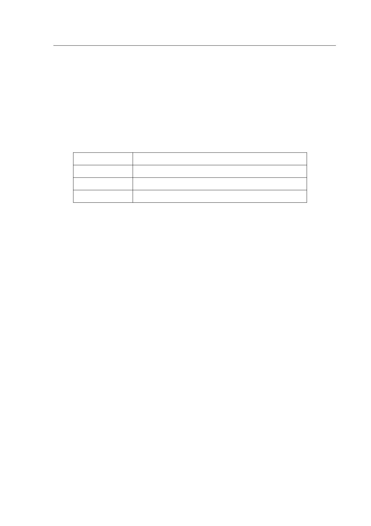
When the servo drive is used in the applications which require high on-off frequency,
please confirm whether the frequency is within the rated frequency range of “H” series
servo drives before you connect the application. The frequency range is determined by
the motor type, the load inertia and the speed of the motor etc. Please refer to the
detailed information from Table 5-8.
Table 5-8
On-off frequency VS Load inertia
Inertia multiples
On-off frequency and ACC/DEC time
J≤3Jmotor
f>100 /min; less than 70Ms
J≤5Jmotor
60<f≤100 /min; less than 130Ms
J>5Jmotor
f≤60 /min;
greater than 150Ms
Note: The above table only provides the on-off frequency in the general cases, the
specific circumstances will vary from the motor types and the load conditions.
5.6.2 Adjustment Method
When the load inertia is five times (or above) greater than the motor inertia, some
errors may occur, such as position overshoot, excessive position deviation and speed
response fault, break abnormal etc.
Under the above situations, you can take relevant actions according to the following
steps:
Step 1: Increase the value of PA5 properly.
Step 2: Decrease the value of PA9 in the meantime. Reduce the inner torque
limitation value PA36.
Step 3: Increase the value of the parameter PA40, PA41 and PA42. (ACC/DEC
time content) along with the S-curve ACC/DEC time content.
Step 4. Increase the ACC/DEC time content of the host system.
You can also consider of selecting a bigger inertia motor to meet your requirement.
49
Chapter 6 Parameters
6.1 Parameter Summary
The defaults of the following parameter table is shown as an example of HSD2-030
drive. The value of the parameters marked “*” may be different from other types.
In the table, Applicable Mode means that the parameter can play a role in a certain
control mode: P refers to position control mode, S refers to speed control mode, T refers
to Torque control mode and ALL refers to all of the control mode(position, speed and
torque control mode).
Input password parameter PA0 =315, you are able to set all parameters except for
PA1.You need to set password PA0 = 302 to do changes about PA1.
Table 6.1
Parameter List
Applicabl
No.
Function Description
e
Range
Default
Unit
Mode
PA-0
Password
ALL
1-1000
315
PA-1
Motor Type Code
ALL
20~200
53*
PA-2
Software Version(read only)
ALL
0~99999
3.85.19*
PA-3
Initial Display Status
ALL
0~19
0
PA-4
Control Mode Selection
ALL
0~5
0
Proportional Speed Loop
PA-5
P,S
1~5000
280*
Hz
Gain
PA-6
Speed Integral Time
P,S
1~1000
30*
ms
PA-7
Speed detection filter
ALL
1~1000
10
0.1ms
Differential coefficient of
PA-8
P
0-100
0
%
position
Proportional Position Loop
PA-9
P
1~1000
100
Hz
Gain
PA-10
Position Feed Forward Gain
P
0~100
0
%
Smooth Constant of Position
PA-11
P
0~1000
25
ms
Feed Forward Gain
Electronic Gear Ratio
PA-12
P
1~30000
1
(Numerator) N1
Electronic Gear Ratio
PA-13
P
1~30000
1
(Denominator) M1
PA-14
External Pulse Input Type
P
0~2
0
50

PA-15
Direction of External Pulse
P
0~1
0
Positioning Completed
PA-16
P
0~30000
20
pulse
Width
Excessive Position Error
×100
PA-17
P
0~30000
400
Range
pulse
Excessive Position Error
PA-18
P
0~1
0
Invalid
Smooth Constant of Position
PA-19
P
0~30000
1
0.1Ms
Command
PA-20
Inhibit Drive Function Invalid
ALL
0~1
1
PA-21
JOG Operation Speed
S
-3600~3600
120
r/min
PA-22
Torque command filter
ALL
1-1000
10
0.1ms
Inner Speed Command
PA-23
S
0~5
0
selection
PA-24
Inner Speed Command 1
S
-3600~3600
0
r/min
PA-25
Inner Speed Command 2
S
-3600~3600
100
r/min
PA-26
Inner Speed Command 3
S
-3600~3600
300
r/min
PA-27
Inner Speed Command 4
S
-3600~3600
-100
r/min
PA-28
Target Motor Speed
S
0~3600
500
r/min
Analog Torque Command
0.1V/100
PA-29
T
10~100
50
Gain(input)
%
Direction of
PA-30
T
0~1
0
Torque Command
Zero-offset Compensation
PA-31
T
-2000~2000
0
for Torque Command
Max speed limit of Torque
PA-32
T
0~3600
1000
r/min
Command
PA-33
DO status monitoring
ALL
000~111
111
PA-34
DI status monitoring
ALL
0000~1111
1111
PA-35
Max speed limit of motor
ALL
0~3600
1000
PA-36
Internal torque limit
ALL
5~600
300
%
Negative torque arrival set
PA-37
ALL
5~300
100
%
point
Positive torque arrived
set point/
PA-38
ALL
5~300
100
%
Maximum torque limit in test
run and JOG mode
Min speed limit under analog
PA-39
speed control mode
S
0~1000
3
51

Time of acceleration for 0 to
PA-40
S
0~10000
0
Ms
1000rpm
Time of deceleration for 0 to
PA-41
S
0~10000
0
Ms
1000rpm
ACC/DEC S-curve duration
PA-42
S
0~10000
0
Ms
time
Analog Speed Command
PA-43
S
10~3000
300
(r/min)/V
Gain
Direction of Speed
PA-44
S
0~1
0
Command
Zero-offset Compensation
-2000
PA-45
S
0
for Analog Speed Command
~2000
Analog speed command
PA-46
S
1~1000
3
mS
filter
Motion control for
PA-47
Electromagnetic Brake when
ALL
0~300
0
×10Ms
motor stops
Motion control for
PA-48
Electromagnetic Brake when
ALL
0~300
50
×10Ms
motor is running
Speed control for
PA-49
Electromagnetic Brake when
ALL
0~3600
100
r/min
motor is running
Sampling Gain for Bus
PA-50
ALL
10~3000
511*
Voltage
PA-51
effective electronic gear ratio
ALL
0~1
0
Electronic gear
PA-52
ALL
1~30000
1
ratio(Numerator 2)
PA-53
Inside SON enable
ALL
0~1
1
Z signal output pulse width
PA-54
ALL
0~1
1
selection
PA-55*
AB output dividing factor
ALL
0~1
0
PA-56
Digital Output effect level
ALL
000~111
000
DO1 function
PA-57
ALL
1~5
1
definition(ALM)
DO2 function
PA-58
ALL
1~5
3
definition(COIN)
DO3 function
PA-59
ALL
1~5
4
definition(BRK)
PA-60
Reserved
167
52

Input vibration elimination
PA-61
ALL
0~100
2
time constant
Digital Import effect level
0000
PA-62
ALL
0000
~1111
PA-63
DI1 function definition(SON)
ALL
1~7
1
PA-64
DI2 function definition(CLE)
ALL
1~7
2
PA-65
DI3 function definition(SC2)
ALL
1~7
3
DI4 function
PA-66
ALL
1~7
4
definition(ALRS)
Note1: “*” next to the parameter numbers means this function may be “reserved” for some models, for
instance,PA-55*, it may not exist or reserved in some models, the detailed information, please consult with our after
sales service center or local distributors.
53

6.2
Detailed Parameter Description
Table 6-2
Detailed description for the parameter settings
Value
NO.
Name
Function description
range
Password
1: Password is 315
0
2: motor type password is 302, you only need this
1~1000
when you are modifying PA1
Motor type
Select the motor type that you are using; in case
code
you need to revise this number, input PA0 is 302,
1
which is the password, finish off your parameters
20~200
setting, power the drive off and on again then the
changes will be effective.
Software
Software version read only, you can’t change the
Version
details, A means the drive power level,
B C D E
means the different software versions.
A=1, 500W;
0~9999
2
A=2, 900W;
9
A=3, 1.5kw;
A=4, 1.5kw;
A=5, 2.5kW;
A=6, 3.5kW.
Initial display
Select the display status when the drive has been
status
powered on:
0: actual motor speed.
1:low data of the feedback position
2:high data of the feedback position
3: Low data of the position command
4: High data of the position command
5: Low data of the position error
3
6: High data of the position error
0~19
7: motor torque
8: motor current(Q axis);
9: Reserved
10: control mode;
11: pulse frequency of position command
12: Speed command
13: Torque command
14: Motor feedback current -position.
54

15: D-axis current
16: Reserved
17: DC bus voltage
18: Drive operation status
19: Error/alarm code;
Control
Select the requested control mode by changing the
Mode
following parameters:
selection
0: Position control mode, controlling the position
command pulse input and output;
1: Speed control mode.
2: Torque control mode
3: Speed trial run control mode, type in the
numbers via keypad, users can test the drive and
motor.
4
0~5
4: JOG control mode, enter the Jog control
operation panel, press and hold the UP key, the
motor will be running at a JOG speed, release the
UP key, the motor stops with a zero speed; press
and hold the DOWN key, the motor will be running
at the JOG speed in a reverse direction, release
the DOWN key, motor stops.
5:zeroing encoder control mode, set PA4=5 will
enter this mode directly.
Proportional
Generally speaking, increase this value can
Speed Loop
improve response performance and reduce the
Gain
error. The default value is 170. The gain should be
increased if the load inertia is relatively high.
1~5000
5
Generally if the load inertia is greater, the value
Hz
should be modified larger. You can increase the
gain as much as possible without causing big noise
and obvious vibration.
Integral Time
The value of the integral time has an effect on the
of Speed
response performance of the speed control loop.
Control Loop
The lower the value is, the quicker the speed will
be, however, when the value is too low, it may
1~1000
6
cause overshoot. Users need to adjust the value by
Ms
the motor type and load inertia etc. Generally,
having a big load inertia requires a bigger value
setting.
55

Speed
1.the bigger this value is, the lower the cut-off
Detection
frequency will be, less produced noise from the
Filter
time
motor. If the load inertia is being very high, please
constant
increase this value considerably without causing
1~1000
7
major vibration and noise.
×0.1Ms
2.Decreasing the value can uplift the cut-off
frequency, enhance the speed feedback response
performance.
Differential
The larger the value, the faster the speed
1~1000
8
coefficient of
response.
×0.1Ms
position
Excessive value may cause motor vibration.
Proportional
Increasing this value can improve the response
Position
performance and position precision. However
1~1000
9
Loop Gain
excessive value will cause vibration and overshoot.
/S
The detailed value will be decided by the motor
type, load inertia etc.
Position
Increasing the value can reduce the position track
Feed
error, set value 100% means the total position error
Forward
is always zero under any frequency pulse. Increase
Gain
this value can enhance the system response
10
0~100%
performance, but will make the position loop
unstable and cause possible vibration. Generally
the set value is 0 unless users require very high
response performance for specific applications.
Smooth
This parameter is used to set the time constant of
Constant for
low-pass filter for position feed forward gain. The
0~1000
11
position feed
function of this low-pass filter is to maintain the
×0.1ms
forward
stability of position control.
Electronic
Under the control mode, users can matching
Gear Ratio
different types of pulse commands and achieve
(Numerator)
their desired resolutions (angle/pulse) by adjusting
N1
PA12 & PA13.
The electronic gear ratio can be calculated as the
1~
following :N1/M1 =F2/(S1*P1)
12
30000
P1:Number of pulses corresponding to 1mm in the
host controller
F2:Number of encoder pulses per circle (Default is
10000)
S1:Screw pitch of the mechanical transmission
56