HSD2 Series Servo Drive. User Manual - page 1
Contents
CHAPTER 1
PRODUCT DESCRIPTION
1
1.1 HSD2 SERIES SERVO DRIVES
1
1.2 APPEARANCE
1
1.3 EXPLANATION OF EACH POWER TERMINALS
2
1.3.1 P / D / C terminals
2
1.3.2 R / S / T terminals
2
1.3.3 R / T terminals
3
1.3.4 U / V / W / PE terminals
3
1.3.5 CN1 connector
3
1.3.6 CN2 connector
3
1.3.7 CN3 connector
3
CHAPTER 2
INSTALLATION & WIRING
4
2.1 PRE-CHECK BEFORE INSTALLATION
4
2.2 PRODUCT SIZE
5
2.3 SIZE DATA FOR INSTALLATION
5
2.4 INSTALLATION ENVIRONMENT
6
2.5 INSTALLATION PROCEDURE & MINIMUM CLEARANCES
7
2.6 CONNECTION TERMINALS
9
CHAPTER 3 SIGNAL INTERFACE AND WIRING
12
3.1 OVERVIEW
12
3.2 CN1 ENCODER CONNECTOR
12
3.2.1 CN1 connector view and layout
12
3.2.2 Signal definition for CN1
13
3.3 CN2 CONNECTOR VIEW AND LAYOUT
13
3.4 SIGNAL DEFINITION OF CN2 CONNECTOR
14
3.5 I/O INTERFACE
16
3.5.1 Digital signal input interface
16
3.5.2 Digital signal output interface
16
3.5.3 Pulse command input interface
17
3.5.4 Analog signal input interface
17
3.5.5 Encoder signal output interface
18
3.5.6 Encoder open-collector Z-pulse output interface
20
3.5.7 Encoder feedback signal input interface
20
3.6 STANDARD CONNECTION EXAMPLE
21
3.6.1 Position control mode
21
3.6.2 Speed / torque control mode
22
CHAPTER 4 PANEL DISPLAY & OPERATION
23
4.1 PANEL DESCRIPTION
23
VII
4.2 MAIN MENU
24
4.3 MONITORING DISPLAY(DP--)
25
4.4 PARAMETER SETTING(PA--)
25
4.5 PARAMETER MANAGEMENT(EE--)
26
4.6 SPEED TRIAL RUN WITHOUT LOAD(SR--)
27
4.7 JOG TRIAL RUN WITHOUT LOAD(JR--)
27
4.8 ANALOG ZERO-OFFSET ADJUSTMENT (AU)
28
CHAPTER 5 TRIAL RUN AND TUNING
29
5.1 INSPECTION WITHOUT LOAD
29
5.1.1 Apply power to the drive
30
5.1.2 JOG trial run without load
30
5.1.3 Speed trial run without load
31
5.2 POSITION CONTROL MODE
33
5.2.1 Simple position control system
33
5.2.2 Parameters for the position control
35
5.2.3 Electronic gear ratio
37
5.2.4 Position control gain
39
5.3 GAIN ADJUSTMENT
40
5.3.1 Steps for gain adjustment
41
5.3.2 Gain adjustment for speed control loop
41
5.3.3 Gain adjustment for position control loop
42
5.4 ELECTROMAGNETIC BRAKE
42
5.4.1 Parameters of electromagnetic brake
43
5.4.2 Wiring of electromagnetic brake
44
5.5 TIMING
45
5.5.1 Timing for power supply
45
5.5.2 Timing for enable operation
46
5.5.3 Servo enable & servo alarm flowchart
47
5.6 START & STOP
48
5.6.1 On-off frequency and load inertia
49
5.6.2 Adjustment Method
49
CHAPTER 6 PARAMETERS
50
6.1 PARAMETER SUMMARY
50
6.2 DETAILED PARAMETER DESCRIPTION
54
CHAPTER 7
MOTOR TYPE MATCHING
66
7.1 MOTOR TYPE LIST FOR HSD2-020
67
7.2 MOTOR TYPE LIST FOR HSD2-030
68
7.3 MOTOR TYPE LIST FOR HSD2-050
69
7.4 MOTOR TYPE LIST FOR HSD2-065
70
7.5 MOTOR TYPE LIST FOR HSD2-030A
71
VIII
CHAPTER 8
ALARM, PROTECTION FUNCTION & TROUBLESHOOTING
72
8.1 ALARM CODE CHECK LIST
72
8.2 POTENTIAL CAUSE AND CORRECTIVE ACTIONS
74
CHAPTER 9
CONNECTION TO MOTOR
79
CHAPTER 10
SYSTEM CONNECTION
80
IX
Chapter 1
Product Description
1.1 HSD2 Series Servo Drives
HSD2 series drives include five different models: HSD2-020, HSD2-030, HSD2-050,
HSD2-065 and HSD2-030A.
Except for HSD2-030A, which has a barrier screw secure terminal, the rest of above
mentioned models have pinhole type power terminals (P / D / C, R / S / T, r / t, U / V / W
/ PE)
CN1, CN2, CN3 are signal connectors.
Please refer to the power level table (1-1) for each HSD2 series servo drives:
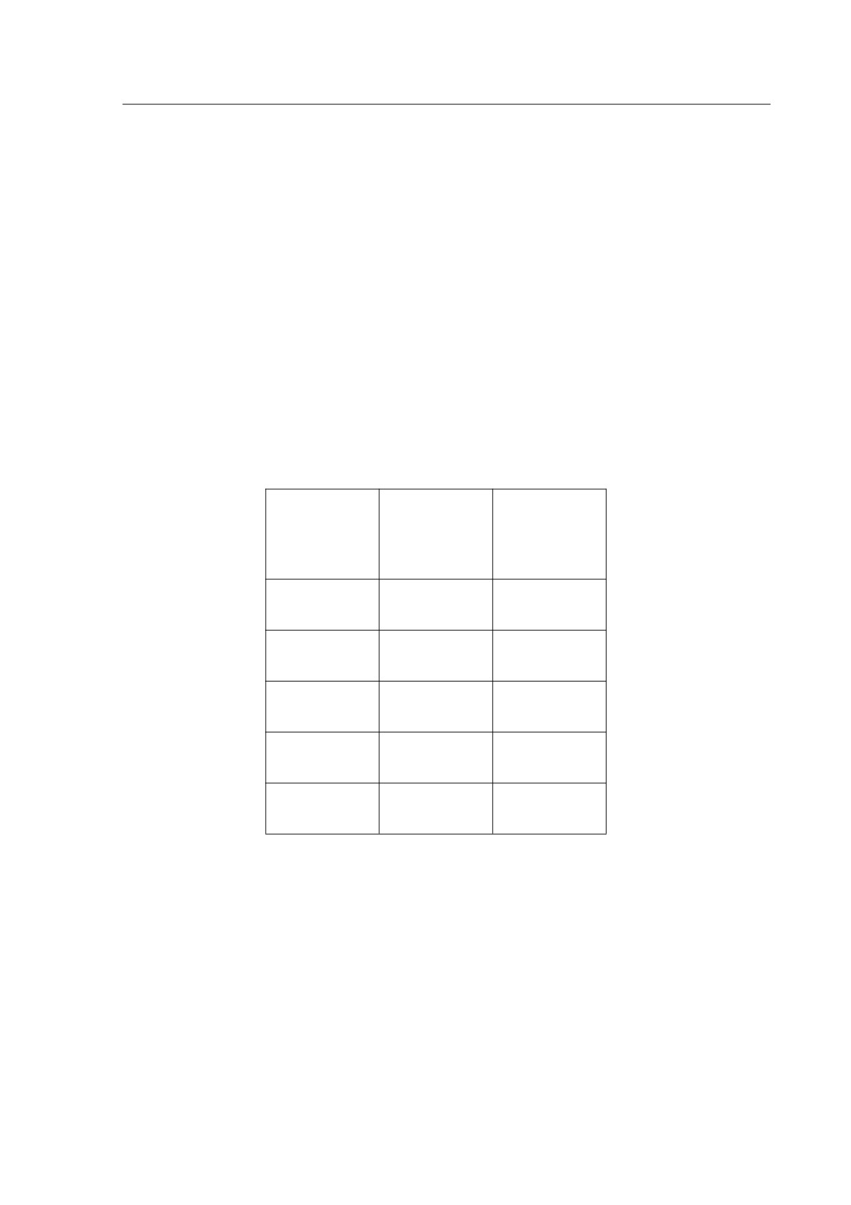
Table 1-1
Power level of HSD2 series drivers
POWER
IPM
TYPE
LEVEL
(A)
(kw)
HSD2-020
20
1.0
HSD2-030
30
1.5
HSD2-050
50
2.5
HSD2-065
65
3.5
HSD2-030A
30
1.5
1.2 Appearance
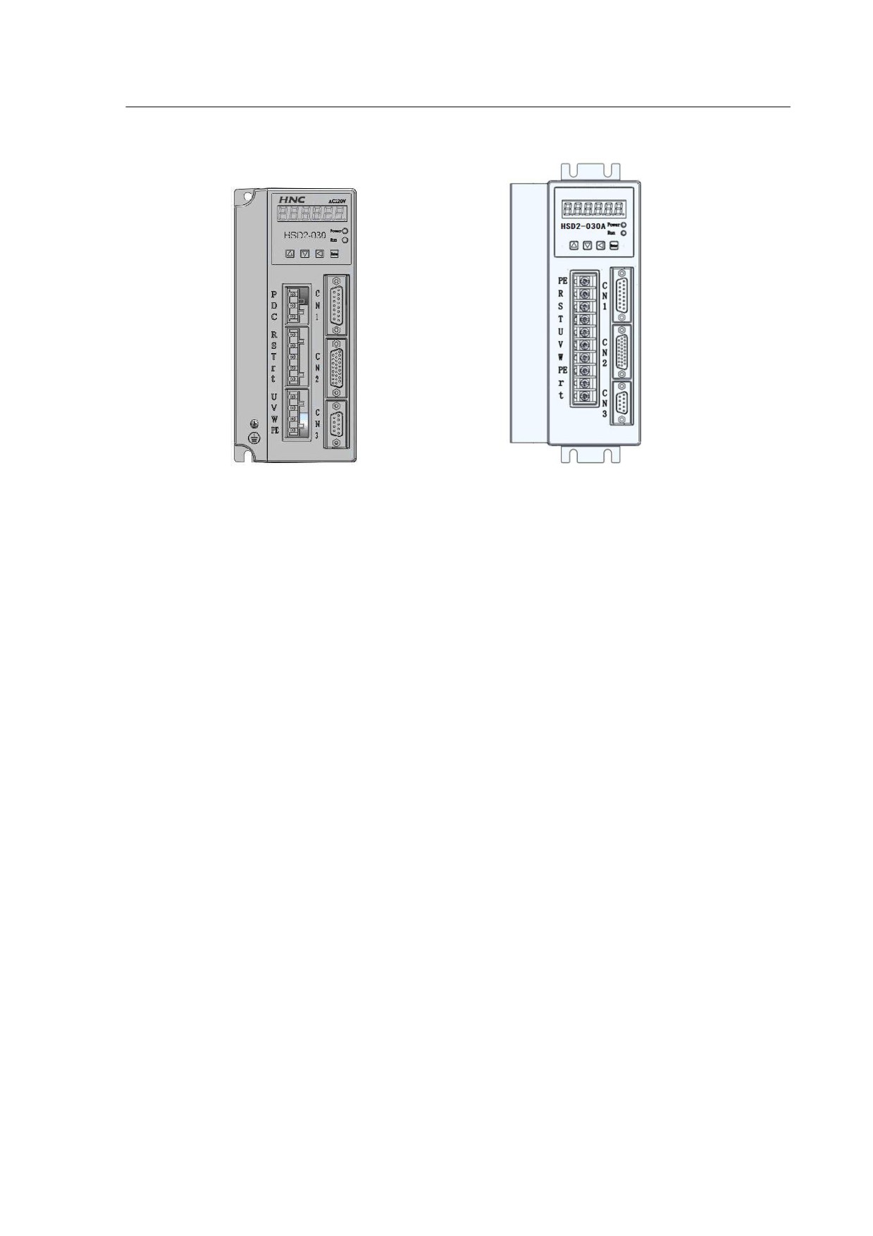
The appearance of HSD2-030, HSD2-050, HSD2-065 are the same. They have
designed with P / D / C, R / S / T / r / t terminals and CN1, CN2, CN3 connectors..
HSD2-020 doesn’t have P / D / C terminals and CN3 connector..
The power terminal of HSD2-030A differs from the rest of four models, it has not
equipped with P / D / C ports additionally.
1
HSD2-030
HSD2-030A
Figure 1-1 appearance of HSD2
1.3
Explanation of Each Power Terminals
1.3.1 P / D / C terminals
1. P / D / C are the wiring terminals of brake resistor.
2. It is prohibited to connect P and C directly, this will damage the drive.
3. When P and D is connected, it means the inner brake resistor is effective, the
default setting is P and D being connected.
4. If an extra break resistor is needed, it will be connected between P and C.
5. If P and D is connected, an extra external break resistor is connected
between P and C, both the internal and external resistors are working on a
parallel basis.
1.3.2 R / S / T terminals
R / S / T are the three phased AC 220V power supply connection terminals, no
phase sequence requirement.
Do not connect AC 380V power supply to the R/S/T terminals, otherwise it will
damage the drive and cause personnel injury.
2
1.3.3 R / T terminals
R/T are the power supply terminals for the control system of the servo drive, AC
220V power supply is required in this case.
It will cause damages to the drive if you connect AC 380V power supply to
these two terminals.
1.3.4 U / V / W / PE terminals
U / V / W / PE are the power output terminals of the drive, they can be
connected to the corresponding ports of the servo motor.
The power cable is generally supplied by the manufacturer, if you need to make
the power cable by yourself, please make sure you use the right shielded wire and
ensure a correct connection of U / V / W / PE terminals to avoid loosing control of
the drive.
Please follow up the instructions from table 2-3 and table 2-4.
1.3.5 CN1 connector
CN1 is the encoder signal interface,it’s used to receive position signals from
servo motor.
Only incremental encoder is applicable to our HSD2 series servo drive.
Incremental encoder has 6 signals: U V W A B Z, adopting differential output for
each signal. The encoder resolution is
2500 PPR, please find the detailed
definitions from table 3-1.
1.3.6 CN2 connector
CN2 is the control signal interface, detailed definitions, please refer to table 3-2.
1.3.7 CN3 connector
CN3 is the communication interface, it is a reserved port at the time being.
3
Chapter 2
Installation & Wiring
In this chapter, you will find the related information and cautions for storage,
installation environment, wiring of HSD2 series servo drive.
1. If the driver is severely damaged during transportation, please do not power on
the drive, contact the supplier for further actions.
2. Do not connect AC 380V power supply to R/S/T terminals.
3. Please ensure PE port is properly connected and earthed.
2.1 Pre-check Before Installation
After receiving the AC servo drive, please check for the following:
Ensure that the product is what you have ordered.
Please check the nameplate to identify if the product you received is what you’ve
ordered from the supplier. (You can refer to Section 1.1 and 1.3 for more details about
the model explanation).
Check the appearance to see if there is any damage.
Please inspect the product carefully to see whether or not there is any damage
during transportation or shipping. Turn the motor shaft by hand, a smooth rotation
indicates a good motor. However, a servo motor with an electromagnetic brake can not
be rotated manually.
Check the screws
Ensure that all necessary screws are tightened and secured.
If any items are damaged, please inform the distributor whom you purchased the
product from or your local sales representative.
4
2.2 Product Size
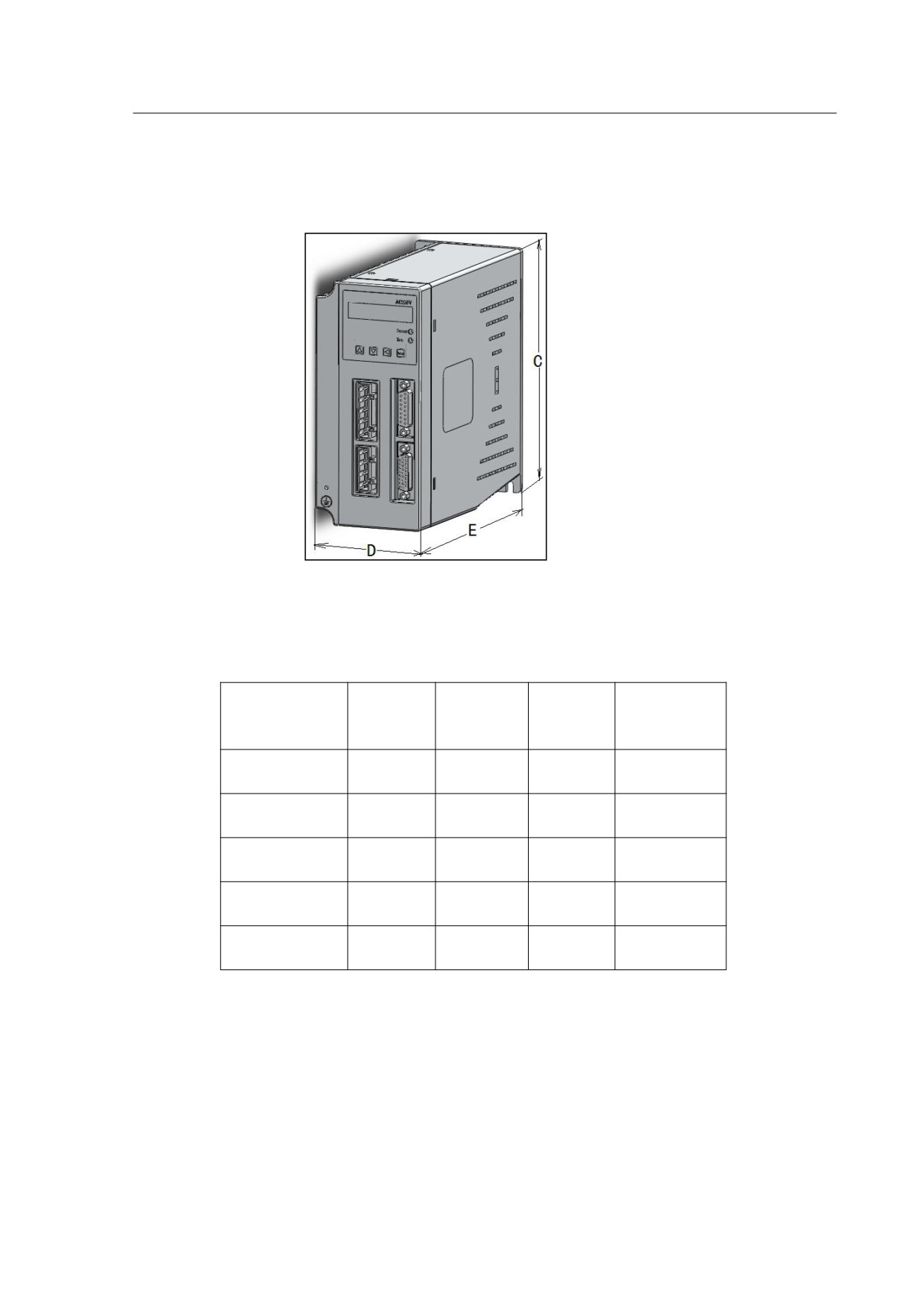
Product size of HSD2 series servo drives, please refer to Figure 2-1 and table 2-1.
Figure 2-1
Dimensions sketch
Table 2-1
size details of HSD2 series drives
Heat sink
Type
C(mm)
D (mm)
E(mm)
depth(mm)
HSD2-020
170
77
172
16
HSD2-030
185
82
182
21
HSD2-050
200
92
186
31
HSD2-065
215
105
207
29.5
HSD2-030A
195
97
155
34
2.3 Size Data for Installation
Please refer to the installation size from Figure 2-2 and Table 2-2.
5
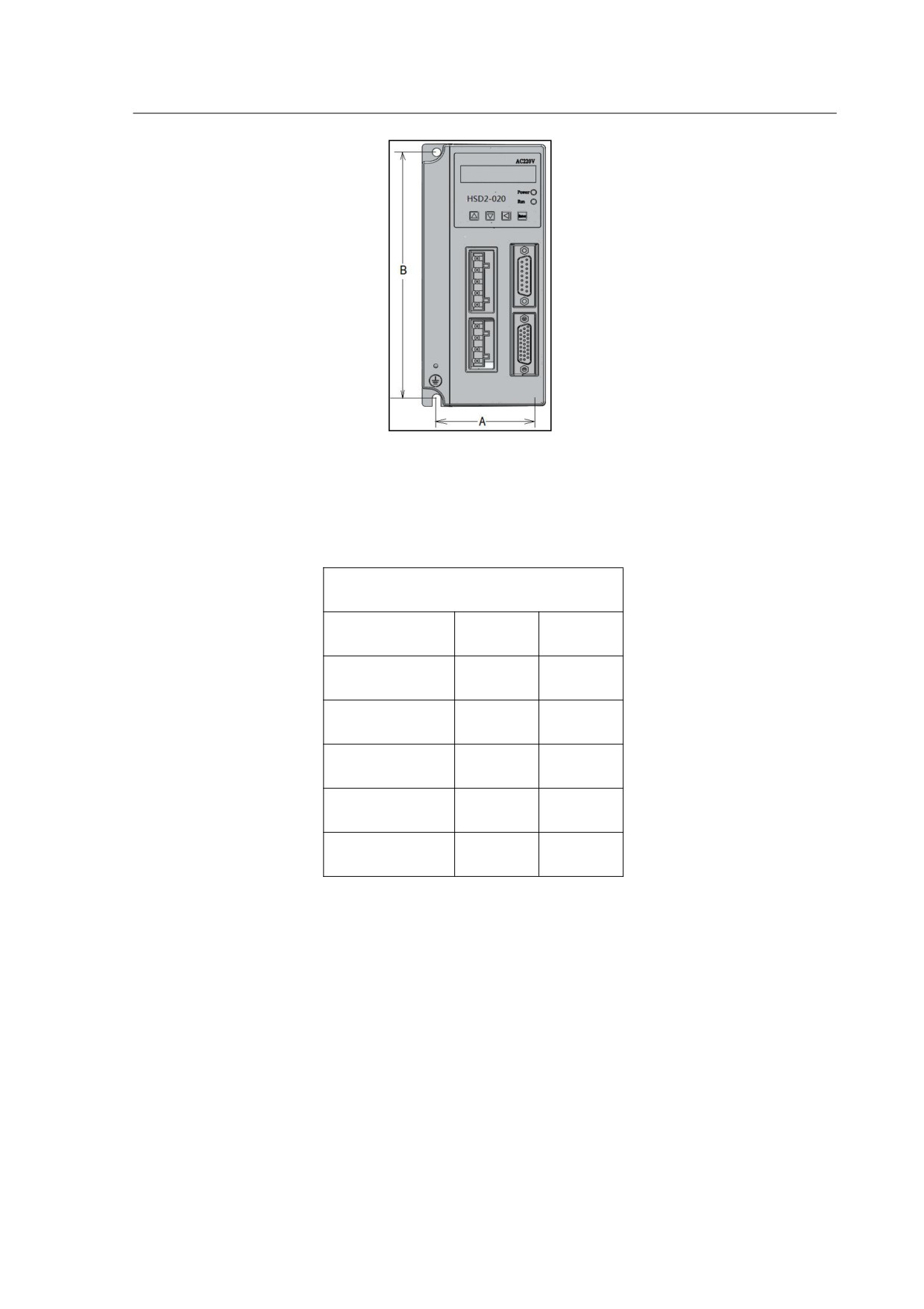
Figure 2-2
installation size sketch
Table 2-2
installation size data for HSD2 series drives
Installation size data
Type
A(mm)
B(mm)
HSD2-020
60
160
HSD2-030
65
175
HSD2-050
75
189.3
HSD2-065
88
203.5
HSD2-030A
25
208
2.4 Installation Environment
The operating temperature for the HSD2 series servo drive is ranging from 0℃
(32°F) to 55℃(131°F). If the ambient temperature of servo drive is higher than 45℃,
please install the drive in a well-ventilated location and do not block the ventilation holes.
The ambient temperature of servo drive for long-term reliability should be under
45℃(113°F).
If you need to install the servo drive and motor in a confined space, please ensure
sufficient space around the units and make sure the ventilation status and size of the
confined space won’t cause overheating of the product. In addition, please also pay
6
your attention to the following cautions:
1. The ambient humidity should be less than 80%, without condensing.
2. Please keep the servo drive or motor away from the heat-radiating
equipment or in direct sunlight.
3. Do not install the drive or motor in a location subjected to the environment
which contains water, corrosive gas or liquid, dust or oily dust, floating dust, metallic
particles.
4. Do not mount the servo drive or motor in the places where it will be subjected
to high levels of electromagnetic radiation.
5. Do not mount the servo drive or motor in a location where temperature and
humidity will exceed specification.
6. Do not mount the servo drive or motor in a location where vibration and
shock will exceed specification.
7. The mounted position vibration should be less than 0.5G.
2.5 Installation Procedure & Minimum Clearances
Incorrect installation may result in a drive malfunction or premature failure of the
drive. Please follow the guidelines in this manual when installing the servo drive.
1. The servo drive should not be tilted or upside down. Please mount the drive
perpendicular to the wall or in the control panel, otherwise malfunction and damage will
occur.
2. The servo drive should be mounted in the control panel with a cooling fan, to
enhance air circulation and cooling.
3. In order to ensure the drive is well ventilated, ensure that the all ventilation holes
are not obstructed and sufficient free space is given to the servo drive. To define the
free space, please refer to the section “Minimum Spacing”.
4. Please tighten the screws for securing drive or motor. Otherwise it may result in
product damage or personnel injury.
5. As the drive conducts heat away via the mounting, the mounting plane or surface
should not bring heat into the drive from external sources.
7
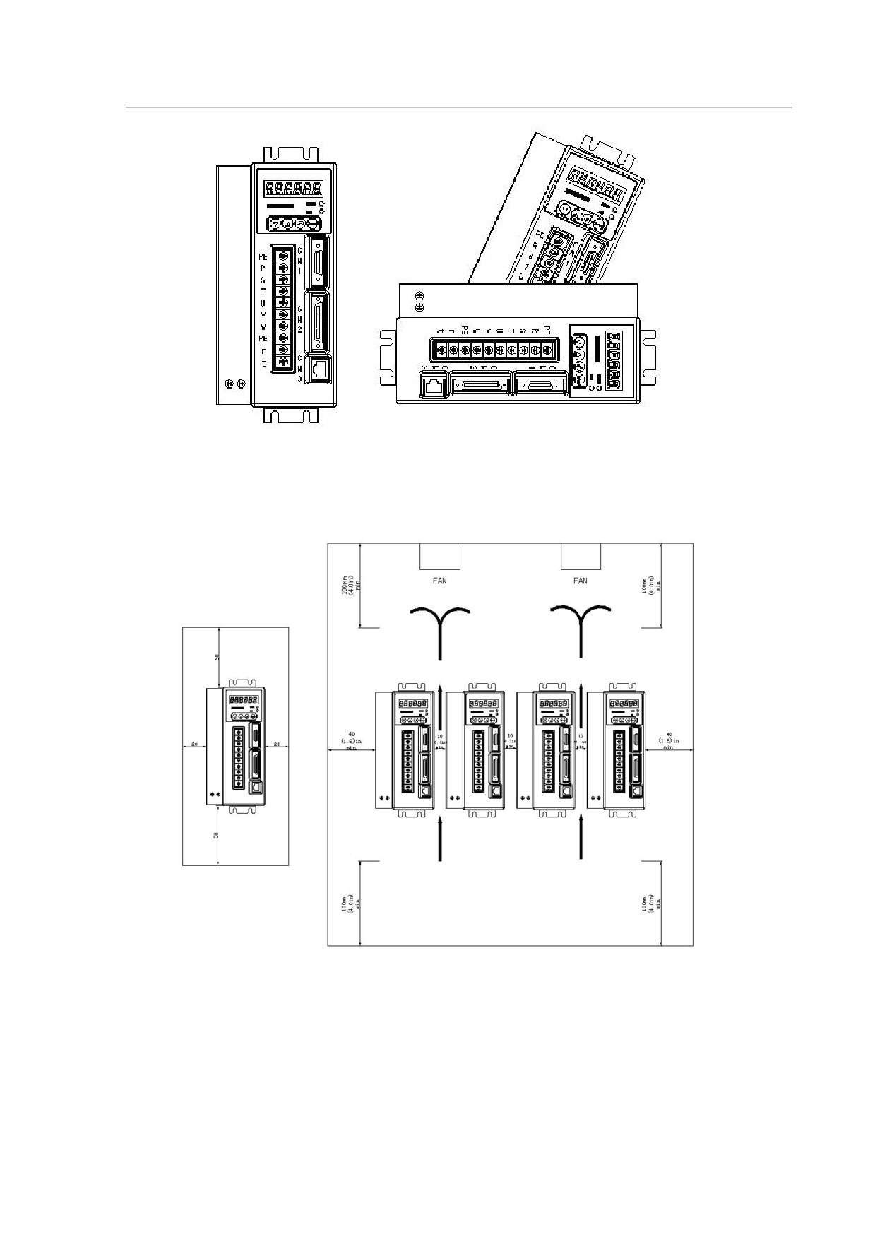
Correct
Incorrect
Figure2-3
The correct direction for mounting
Figure 2-4
Installation Minimum Spacing
In order to increase ventilation to avoid ambient temperature being exceed to
specification, please install a fan. A minimum spacing of two inches must be maintained
above and below the drive for ventilation and heat dissipation. Additional space may be
necessary for wiring and cable connections. When installing two or more drives next to
each other, please follow the spacing diagram from the above Figure 2-4.
8
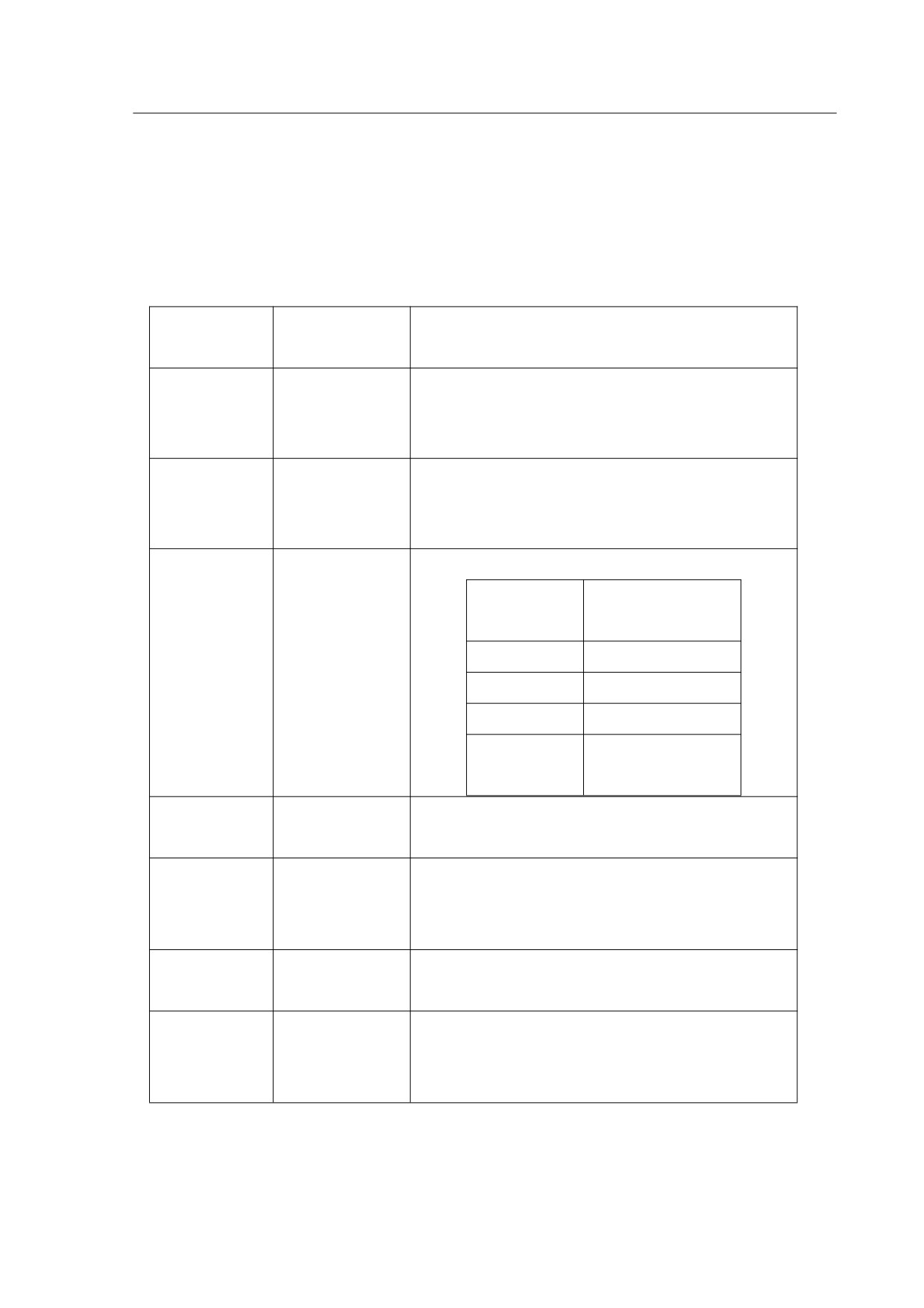
2.6 Connection Terminals
Please select the connecting terminals carefully and follow the instructions
from
table
2-3 and 2-4.
Table 2-3
Definition and function of the terminals
Terminal
Terminal
Descriptions
Identification
Description
Used to connect three-phase AC main circuit
Main circuit
power depending on connecting servo drive
R、S、T
terminal
model.
Used to connect single-phase AC control
Control circuit
circuit power. (Control circuit uses the same
R、t
terminal
voltage as the main circuit.)
Used to connect servo motor
Terminal
Wire colour
symbol
U、V、W、
Servo motor
U
Brown
PE
output
V
Black
W
Grey
Yellow and
PE
green
Ground
Used to connect with the grounding wires of
PE
terminal
power supply and servo motor.
Used to connect with the encoder of servo
Encoder
CN1
motor. Please refer to section 3.2 for more
connector
details.
Used to connect with external controllers.
CN2
I/O connector
Please refer to section 3.3 for more details.
Communicatio
Connect with personal computer
(PC or
CN3
n connector
laptop).
(Reserved)
9
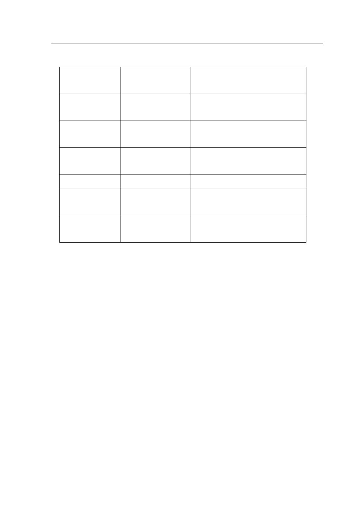
Table
2-4
Cable specifications for the terminals
Terminal
Terminal
Cable specification
Identification
Description
Main circuit
R、S、T
1.5~2.5mm2
terminal
Control circuit
r、t
0.75~1 mm2
terminal
U、V、W
Servo motor output
1.5~2.5 mm2
PE
Ground terminal
1.5~2.5 mm2
≥0.14 mm2, 7 pair shielded
CN1
Encoder connector
twisted-pair cable
≥0.14 mm2, shielded twisted-pair
CN2
I/O connector
cable
Wiring Cautions
Please read and follow up the below wiring precautions while performing wire
connections with the servo drive and servo motor.
1. Please ensure that the wiring of the main power supply terminal R/S/T and
control power supply terminal R/T are properly selected and connected, power
specification is correct.
2. Please use shielded twisted-pair cables for wiring to voltage coupling and
eliminate electrical noise and interference.
3. Please ensure a correct connection for U, V, W terminals, or it may not be able to
start the motor or cause galloping.
4. The ground terminal of the servo motor should be connect with the PE of the
servo drive properly and ensure a single point grounding. The grounding cable requires
to be coarse as well.
5. As a residual hazardous voltage may remain inside the drive, please do not touch
any of the terminals (R, S, T, & U, V ,W) or the cables connected to them after the
power has just been turned off. Wait for at least 10 minutes until the charging light is off
10
before you take any further actions with the drive.
6. With regards to the I/O signal cable, please use the recommended cable or
similar shield cable. The total length of I/O signal cable shouldn’t exceed 3 meters,
while encoder cable should be less than 15 meters. Please use a twisted-shield signal
wire with grounding conductor for the encoder cable (CN1) and the position feedback
signal connector (CN2). The wire length shouldn’t exceed 20meters. If it exceeds 20m,
please choose a bigger wire diameter (double the existing one) of signal cable to
reduce the signal fading.
7. The shield of shielded twisted-pair cables (encoder cable) should be connected
to the SHIELD end (ground terminal) of the servo drive.
8. The cables which connected to R, S, T and U, V, W terminals should be placed
in separate conduits from the encoder or other signal cables. Separate them by at least
30cm.
9. Please ensure the diode connecting direction of signal output relay is correct,
otherwise it may lead to malfunction of the drive.
10. Please install a non fuse type circuit breaker (NFB) to achieve external power
cut offs when the servo drive is in a malfunction status.
11. Shut down the power supply if the servo drive is not being used for a long term.
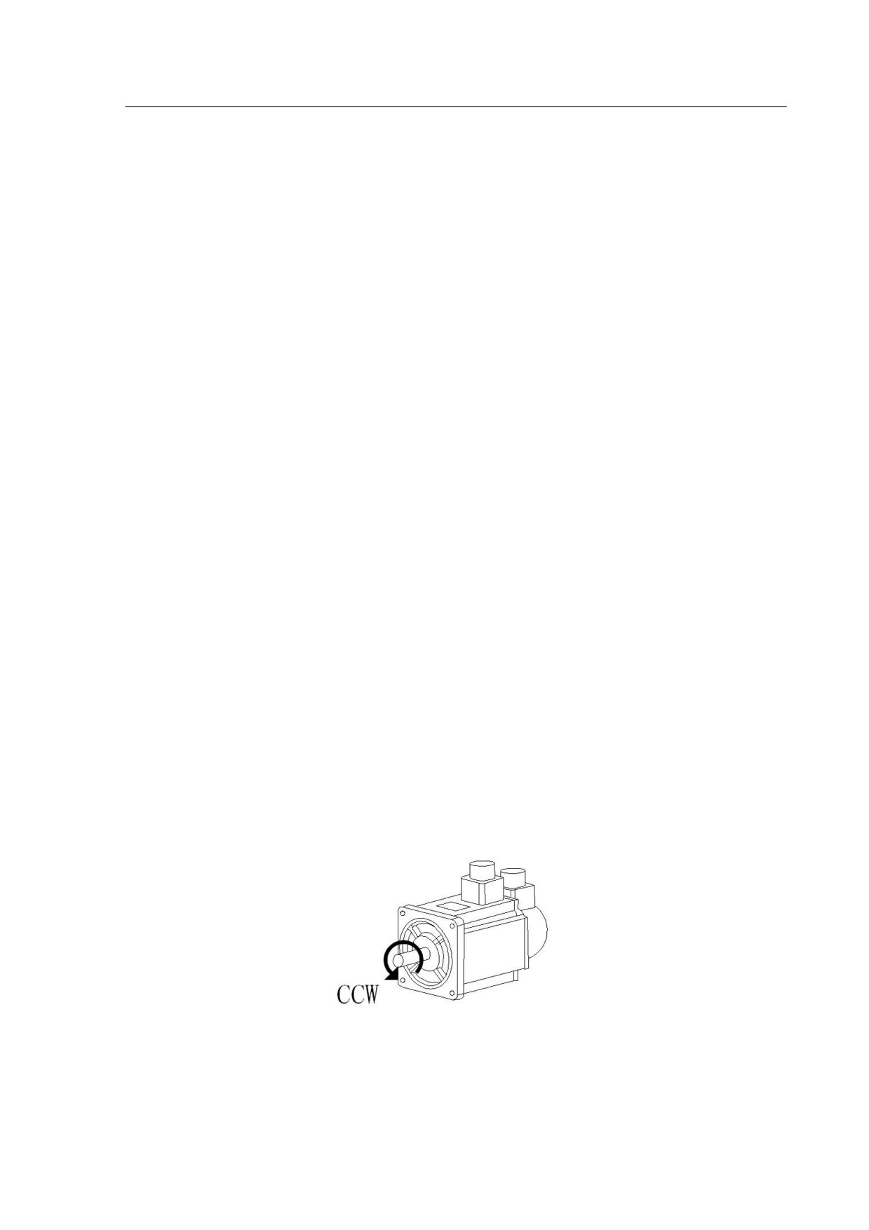
12. Definition of rotating directions: face the motor shaft, the counter-clockwise
direction is defined as the CCW. And the clockwise direction of rotation is defined as the
CW. Generally, we refer the CCW as the positive direction, while CW as negative
direction.
Figure 2-5
Definition of rotating directions
11
Chapter 3
Signal Interface And Wiring
CN1, CN2, CN3 are the signal interfaces of the servo drive, while CN3 is the
communication port, (reserved).
This chapter provides the definitions and standard wiring/connections for the three
ports.
3.1 Overview
1. CN1 is an encoder connector, used for receiving position signals from servo
motor.
2. HSD2
series servo drive is only applicable with incremental optical
encoder(resolution 2500ppr)
3. Incremental optical encoder includes 6 signals: U V W A B Z respectively. It
adopts differential encoder signal output(15-line output generally).
4. CN2 is the I/O connector, used to receive control signal from the controller, and
output the feedback signal to the controller by return.
5. Control signal generally include pulse command signal: PULS+, PULS-, and
direction signal: SIGN+, SIGN-,analog speed command signal :AS+, AS-, drive
signal: SON etc.
6. The feedback signal include encoder signal: A+, A-, B+, B-, Z+, Z-, Z ;signal OC,
output signal :CZ, servo drive alarm signal: ALM+, ALM-, etc.
3.2 CN1 Encoder Connector
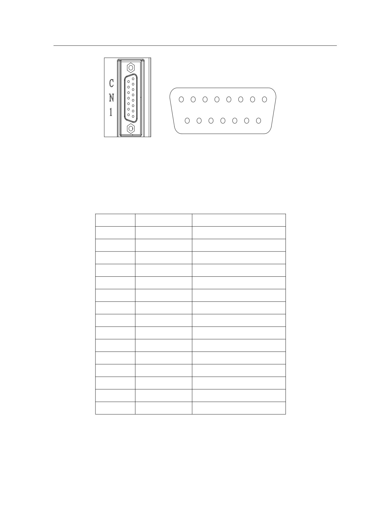
3.2.1 CN1 connector view and layout
CN1 is the encoder connector for the motor, which named as DB26M.Please refer
to the layout from the below Figure 3-1.
12
8
7
6
5
4
3
2
1
15
14
13
12
11
10
9
Figure 3-1
The view and layout of the CN1 encoder connector interface
3.2.2
Signal definition for CN1
Table 3-1
Signal definition for CN1
PIN No.
Identification
Description
1
A+
Encoder signal A+
9
A-
Encoder signal A-
2
B+
Encoder signal B+
10
B-
Encoder signal B+
3
Z+
Encoder signal Z+
11
Z-
Encoder signal Z+
14
U+
Encoder signal U+
6
U-
Encoder signal U-
13
V+
Encoder signal V+
5
V-
Encoder signal V-
4
W+
Encoder signal W+
12
W-
Encoder signal W-
7
+5V
Power supply 5V
8
GND
GND for power supply
15
PE
Shielded wire
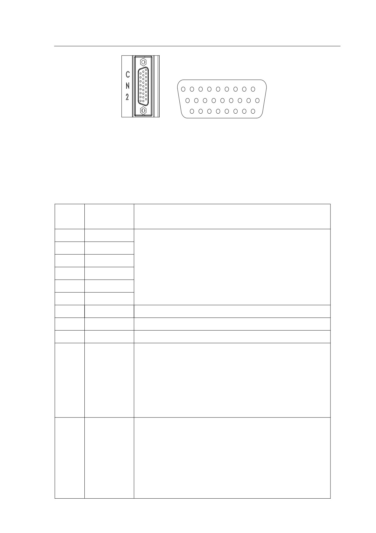
3.3 CN2 Connector View and Layout
CN2 is the signal I/O connector, please refer to the view and layout from the below
Figure 3-2.
13
9
8
7
6
5
4
3
2
1
18
17
16
15
14
13
12
11
10
26
25
24
23
22
21
20
19
Figure 3-2
The
view and layout of the CN2 I/O connector
3.4 Signal Definition of CN2 Connector
Table 3-2
CN2 Signal definition
Termin
Terminal
Description
al No.
Identification
19
OA+
10
OA-
Encoder signal output A, B, Z (Line-driver output ). The
11
OB+
motor encoder signals are available through these
1
OB-
terminals.
2
OZ+
12
OZ-
4
CZ
Encoder signal Z open-collector output.
6
DGND
Encoder digital signal ground
16
COM+
power input (DC 12-24V) positive end
Servo drive enable signal input terminal:
SON ON: enable the drive.
SON OFF:drive disabled and the motor is in free status.
14
SON
Note 1:The motor must be still before enabling the drive.
Note 2:Any other command should be inputted after the
SON on signal for 50ms
In the speed control model when PA23=1 the input
terminal is defined as the zero speed clamping function.
When PA4=0 the terminal is defined as deviation zero
ZCLAMP/
reset function
17
CLE/SC1
The input terminal is defined as the speed command
selection SC1 in the speed control model (PA4=1) when
the parameter PA23=0
14
The input terminal is defined as the speed command
selection in the speed control model when PA4=1 and
PA23=0. Used to select the different internal speed
through the combination of SC1 and SC2.
8
SC2
SC1 OFF, SC2 OFF: internal speed 1.
SC1 ON, SC2 OFF: internal speed 2.
SC1 OFF, SC2 ON: internal speed 3.
SC1 ON, SC2 ON : internal speed 4.
7
ALRS
Clear alarm signal
23
DOCOM
I/O signal output ground
21
ALM
Servo Alarm signal
22
BRK
Break release
In the position control mode (PA4=0),
COIN is activated when the position error is equal and
below the setting value of PA16.
20
COIN
In the speed control mode (PA=1),
COIN will be activated when the drive has detected the
motor has reached the Target Rotation Speed setting as
defined in parameter PA28.
13
AS+
Motor speed command:
-10V~+10V, corresponds to
3
AS-
-3000~+3000 r/min command
and the input impedance is 10KΩ
5,15
AGND
analog signal ground
26
PULS+
Position Pulse Input
18
PULS-
24
SIGN+
Position Sign Input
25
SIGN-
9
PE
Shielding earth cable
15
3.5 I/O Interface
3.5.1 Digital signal input interface
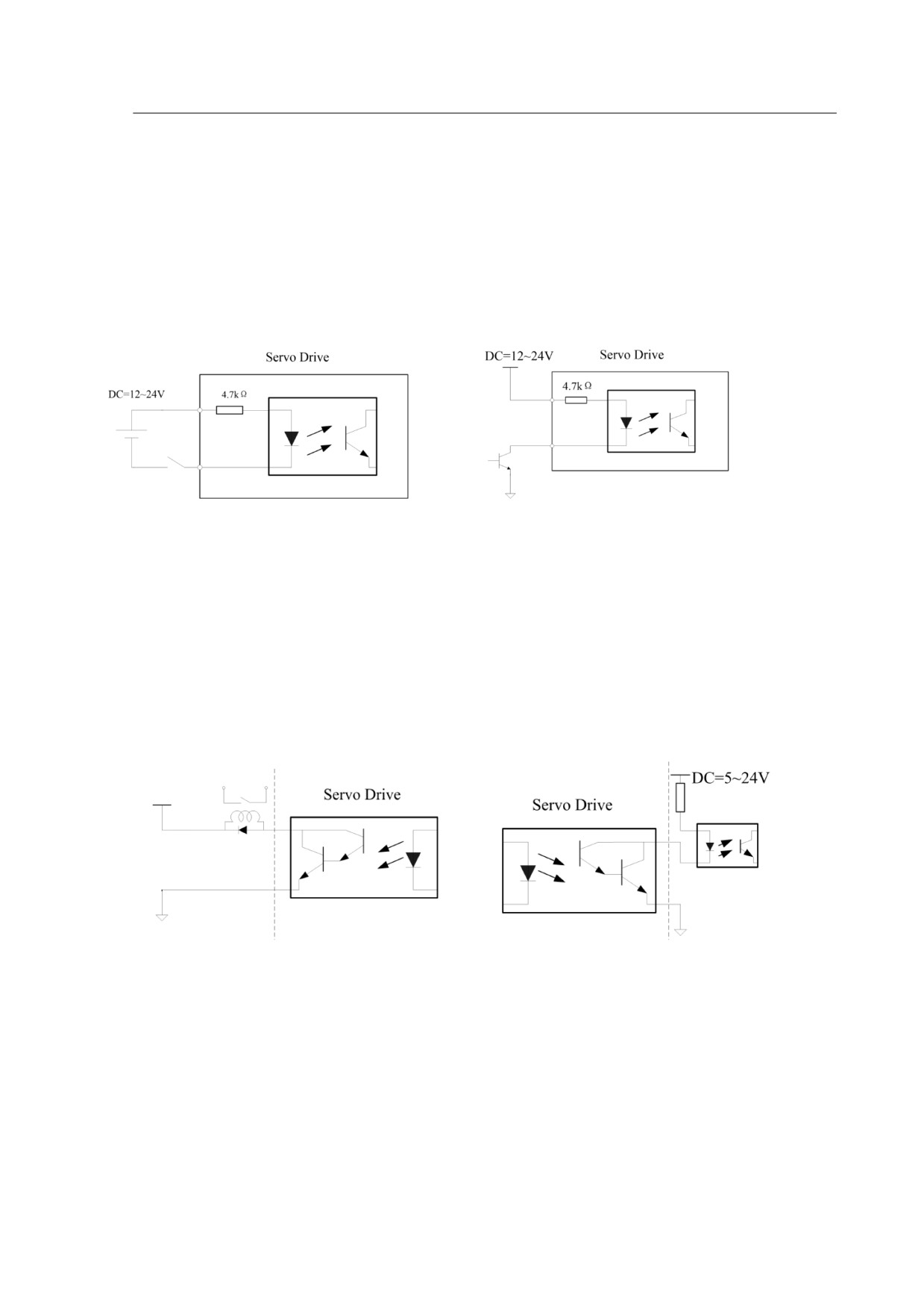
Digital signal input interface circuit is generally composed by optocouplers,
switches, relays, open-collector transistors or other components as shown in the
following diagram(3-3).
Diagram 3-3
Digital signal input interface circuit type 1
1. The voltage of the external power is DC12~24V and available current should be
100mA at least.
2. Ensure that the polarity of the power is correct, otherwise it will damage the drive.
3.5.2 Digital signal output interface
The digital signal output interface circuit is connected with optocoupler or
optocoupler and relays together, achieve the transferring of the isolated digital signal.
Diagram 3-4
Digital signal output interface circuit type 2
1. The voltage of the external power is DC5~24V.
2. The output form of optocoupler is open-collector, the max current is 50mA and
the external max DC voltage is 25V.
3. When inductive components (i.e relays) are on load, please parallel fly-wheel
diode at each end of the component, ensure the correct connection of the polarity,
otherwise, it may damage the drive.
16
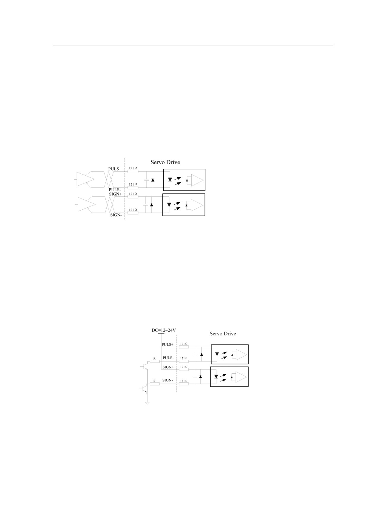
3.5.3 Pulse command input interface
The drive can run two different types of pulse inputs: Line-drive input and
Open-collector input. The maximum input frequency of line-drive input is 500Kpps,with
strong anti-jamming capability, while the Open-collector input type is 200Kpps.In order
to ensure reliable signal transition, the Line-drive input circuit is recommended.
1. Diagram for Line-drive input circuit
In the Line-drive mode, AM26LS31,MC3487 or RS422 is used in the Line-drive
output circuit of the host controller.
Diagram 3-5 Pulse input interface circuit type 3(Line-drive input circuit)
2. Diagram for Open-collector input circuit
The source of pulse input is open-collector PNP equipment which applies the
external power of the servo drive. Please pay attention to the power polarity, incorrect
connection may damage the drive.
By adopting the open-collector input circuit, it reduces the motion frequency, the
driving current of the circuit is between 10~15mA, users can calculate the resistance
value of R according to the power supply voltage.
Diagram 3-6
Pulse input interface circuit type 3(Open-collector input circuit)
3.5.4 Analog signal input interface
There are two different input circuit types of analog signal: differential input mode
17
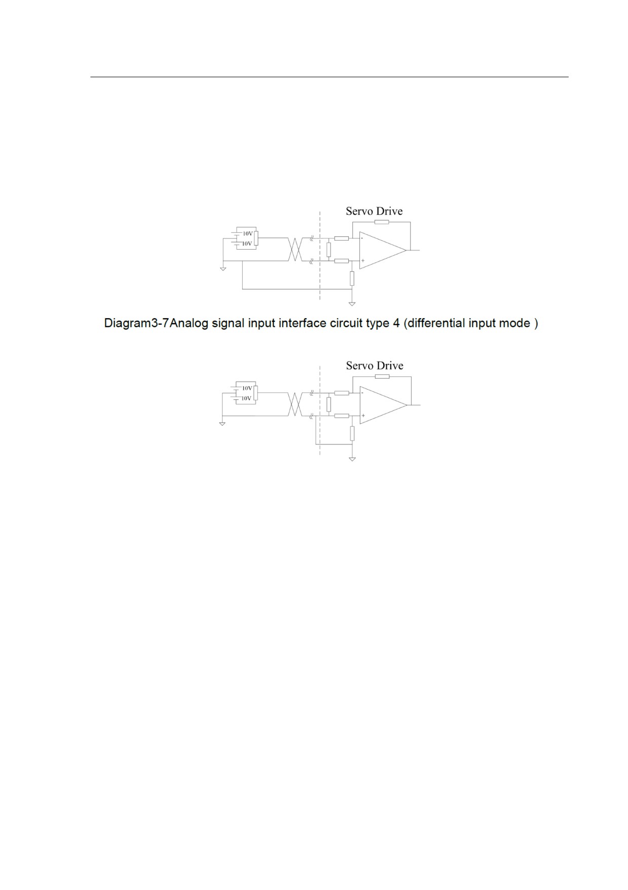
and single-ended input mode. It is recommended to use the differential input circuit as it
can inhibit the common-mode interference.
The valid voltage range of analog input command in speed and torque mode is
-10V~+10V, and the input impedance is 10KΩ .The command value can be set via
relevant parameters. The zero drift of the analog signal could be compensated by
adjusting the parameters.
Diagram3-8 Analog signal input interface circuit type 4 (single-ended input mode)
1. Three connecting wires are needed in differential input mode, but only two
connecting wires required in single-ended input mode.(The wires mentioned here
means the wire from the analog generator.)
Note: under the single ended input mode, the short-circuit is not pre-designed inside of
the servo drive in order to avoid the potential interference. Users need to create the
short-circuit for CN2 side.
2. The voltage of the signal should not exceed the specified range (-10V~+10V) or it
may damage the drive.
3. This interface is a non-isolated input interface, so the shielded cable is
recommended to reduce the noise interference.
3.5.5 Encoder signal output interface
The servo drive output the motor encoder feedback position signals by Line-drive
transmitter chip AM26LS31 to the controller signal input end. The user could receive the
encoder A, B and Z phase signals by two types: Line-drive receiver chip and the
18
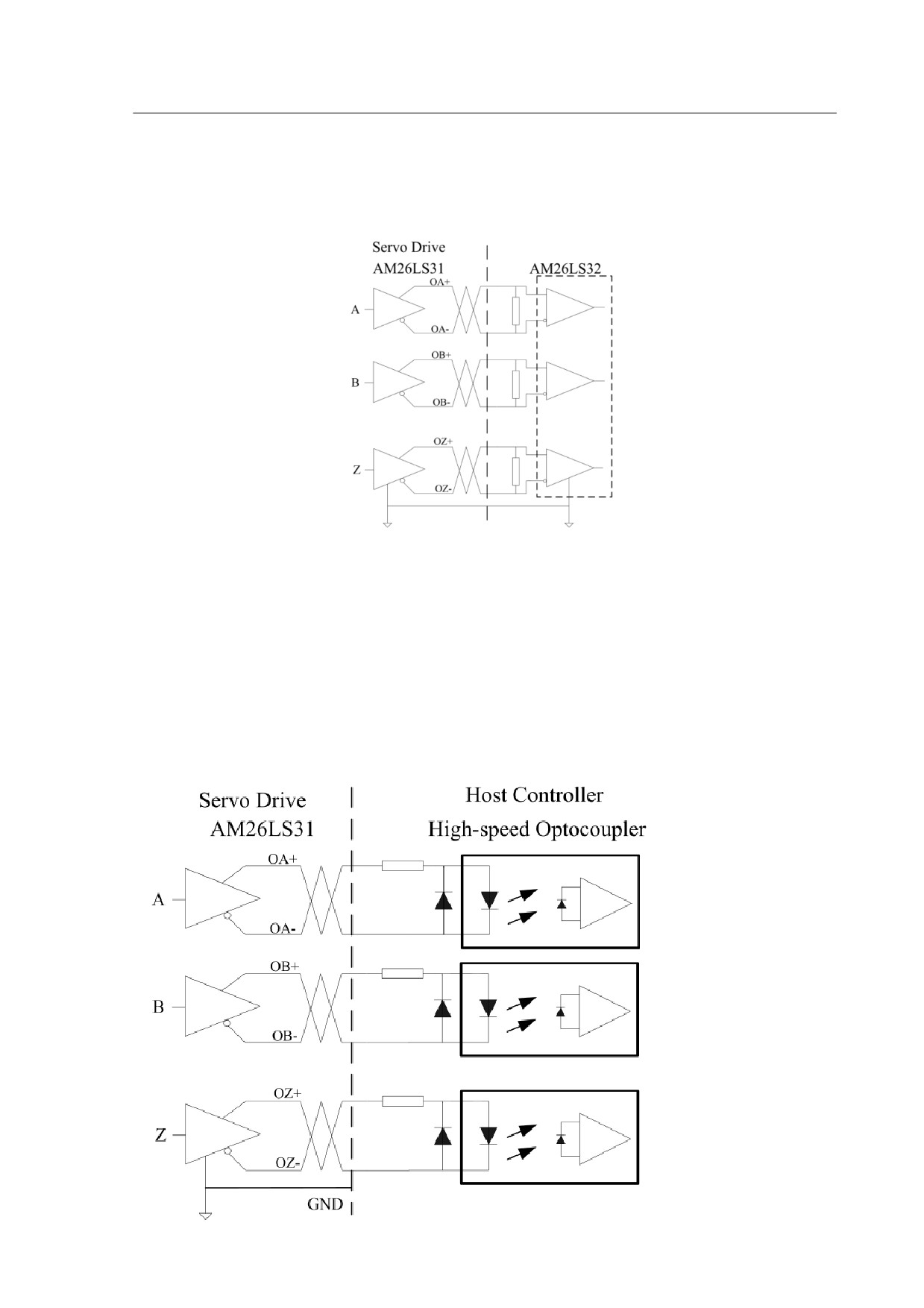
high-speed optocoupler.
The host controller receives the encoder signals by Line-drive receiver chip. Please
refer to the wiring diagram from the below Diagram 3-9
Diagram 3-9 Encoder position signals output interface circuit type 5(Line-drive)
The value of the resistance is 220Ω~470Ω, and the command ground (GND) of the
encoder should connect with the signal ground of the host controller.
When the host controller is receiving the signal by high speed optocoupler, series
resistor is required to be added at the input end of host controller, resistance value is
220Ω approx. Detailed circuit please refer to the below Diagram 3-10.
Diagram 3-10
Encoder position signals output interface circuit type 5(optocoupler)
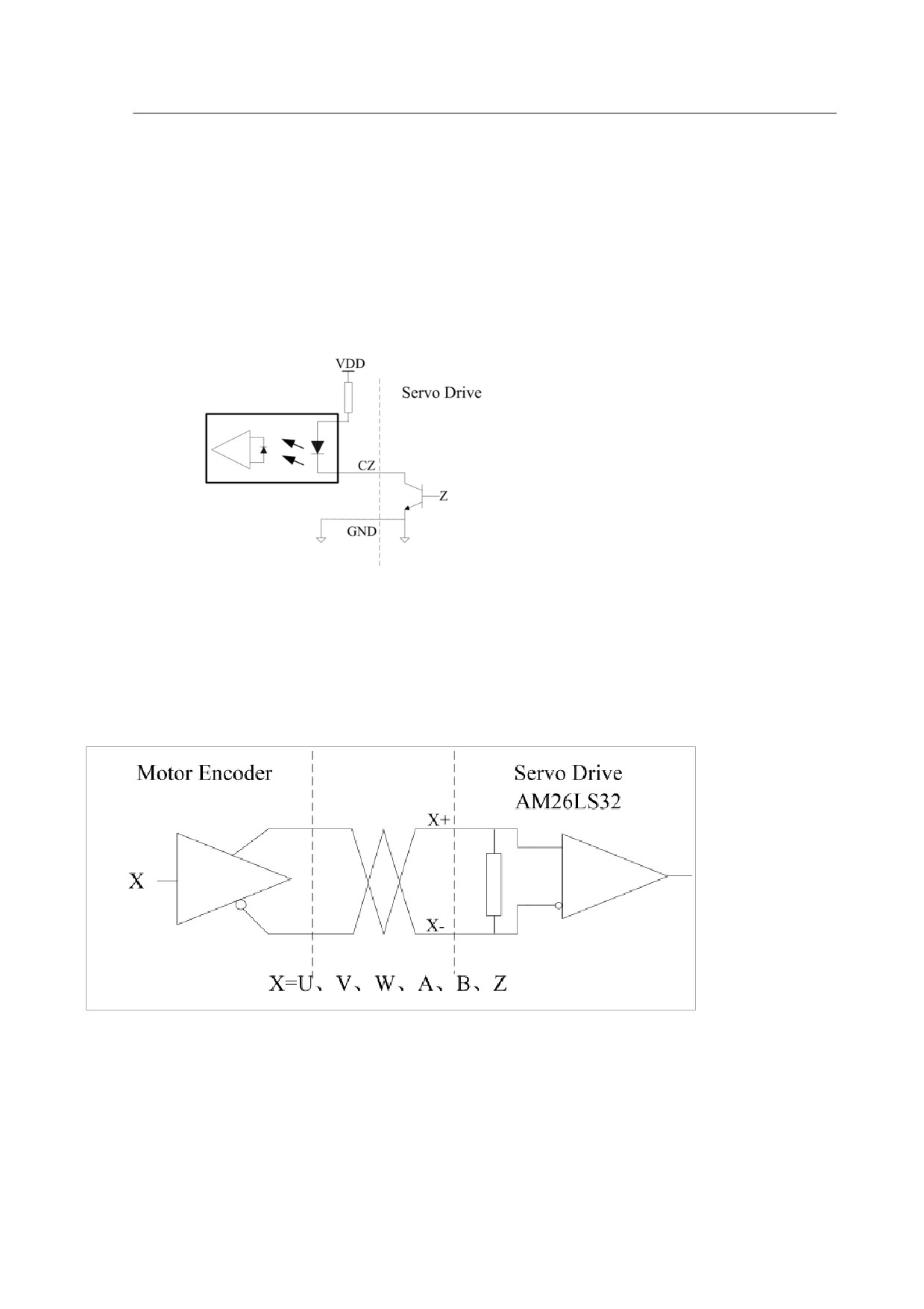
3.5.6 Encoder open-collector Z-pulse output interface
The drive transmit encoder zero position signal Z to the host controller via
open-collector output interface mode. The width of the zero position pulse is narrow,
therefore the high-speed optocoupler is recommended as the receiver. This interface is
a non-isolated input interface, the maximum current is 50mA and the maximum voltage
is 30V. The specific interface circuit is shown as the following.
Diagram 3-11 Encoder Open-collector Z-pulse output interface circuit type 6
3.5.7 Encoder feedback signal input interface
The servo drive adopts AM26LS32 or equivalent IC encoder to receive the
feedback signal, the detailed circuit please refer to the below Diagram 3-12.
Diagram 3-12 Encoder feedback signal input interface circuit type 7
20
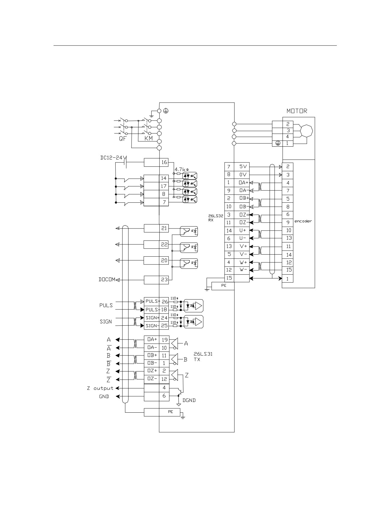
3.6 Standard Connection Example
3.6.1 Position control mode
DRIVER
R
3 PHASE
U
U
AC 220V
S
V
V
T
W
W
r
PE
t
CN2
CN1
COM+
SON
CLE
SC2
ALRS
CN2
ALM
BRK
COIN
D OCOM
PE
C N1
CN2
CN2
CZ
DGND
PE CN2
Diagram 3-13 position control mode
21
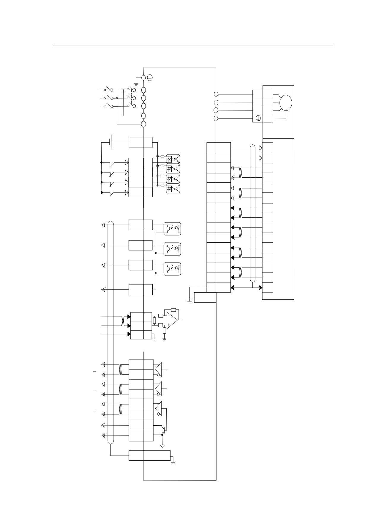
3.6.2 Speed / torque control mode
Motor
DRIVER
R
3 PHASE
2
U
U
S
AC220V
V
V
3
T
W
W
4
QF
KM
r
PE
1
t
DC12-24V
CN2
CN1
COM+
16
7
5V
2
4.7kΩ
8
0V
3
SON
SON
14
1
OA+
4
CLE
CLE
17
9
OA-
7
SC2
SC2
8
2
OB+
5
ALRS
ALRS
7
10
OB-
8
26LS32
3
OZ+
6
CN2
RX
11
OZ-
9
encoder
ALM
ALM
21
14
U+
10
6
U-
13
BRK
BRK
22
13
V+
11
5
V-
14
COIN
COIN
20
4
W+
12
12
W-
15
15
PE
1
DOCOM
DOCOM
23
CN1 metal case
CN2
AS+
13
input of AS
(-10V~+10V)
AS-
3
10k
GND
AGND
5
CN2
A
OA+
19
A
OA-
10
A
26LS31
B
OB+
11
B
TX
B
OB-
1
Z
OZ+
2
Z
OZ-
12
Z
Z (OC)
CZ
4
DGND
DGND
6
DGND
PE
CN2 metal case
22
Chapter 4
Panel Display & Operation
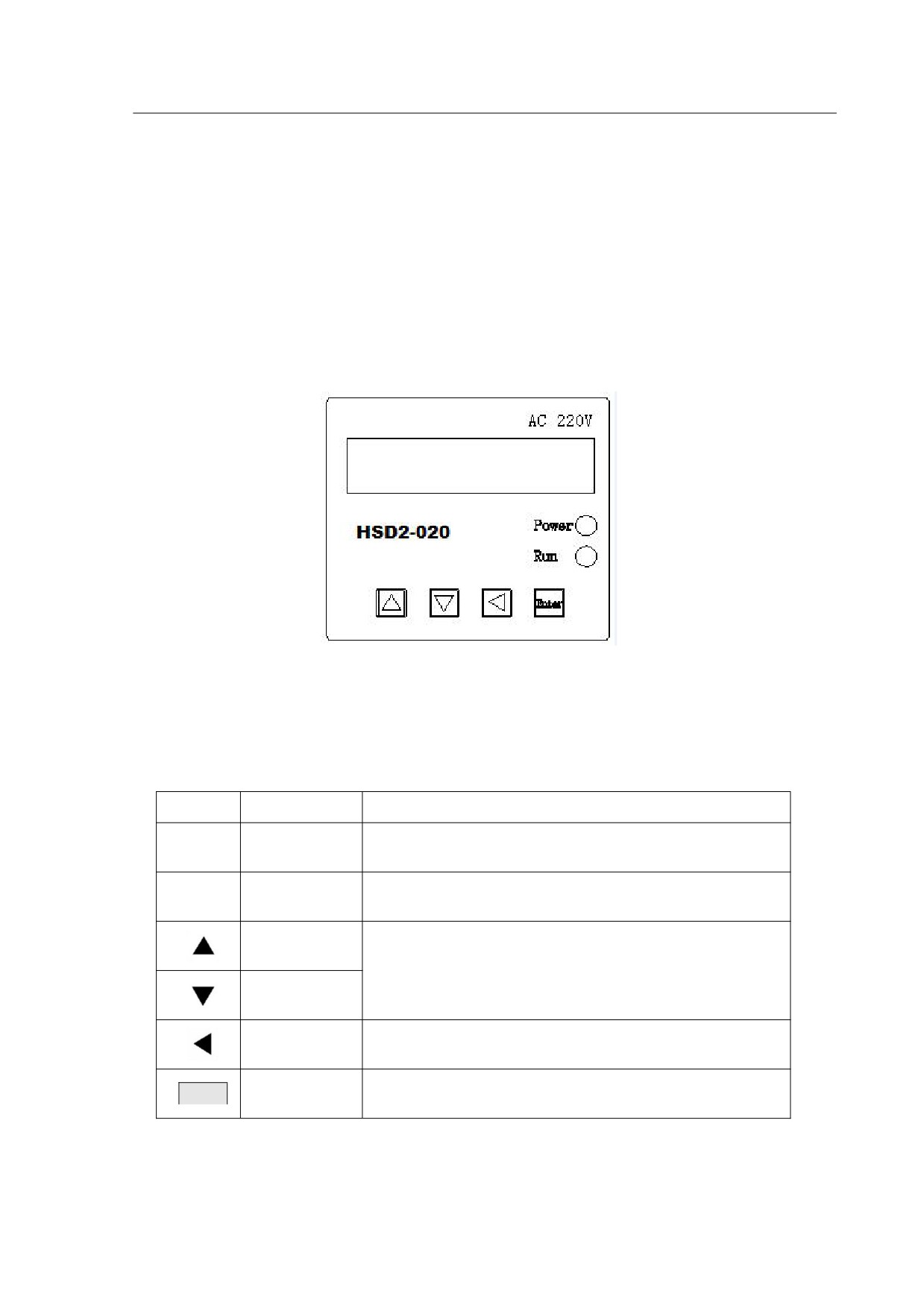
This chapter describes the panel status and basic operations of the digital keypad.
4.1 Panel Description
The operation panel is composed by an LED display panel, and 4 functional
keypads, for the use of displaying current status of the drive, and setting parameters etc.
Please refer the key functions from Table 4-1 and overview of the panel from Figure 4-1
Figure 4-1
Display Panel overview
Table 4-1
Function descriptions
Symbol
Name
Function
Power
The LED light indicates the control power is
Power
supply
applied to the circuit.
Running
The LED light indicates the main power is applied
Run
status
to the circuit and the drive is OK to be started.
Up key
Pressing the Up and Down key can scroll through
and change monitor codes, parameter groups and
Down key
various parameter settings.
Pressing the Return key can exit the menu or
Return key
cancel the operation or the settings.
Pressing the Set key can enter the menu or save
Enter
Set
the operation /the parameter settings.
Note :The 6 segment LED display is blinking means there is a failure or alarm.
23
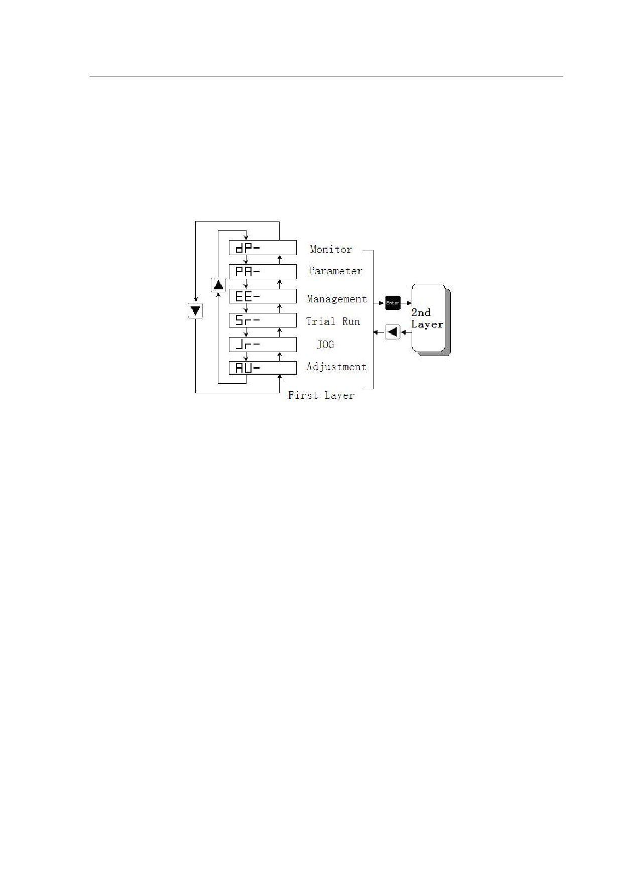
4.2 Main Menu
As the first layer of the operation panel, the main menu consists six sections. You
can use the Up and Down key to change the content of the main menu display and
press the Set key to enter the secondary menu, you can also press the Return key to
quit the secondary menu and back to the main menu.
Figure 4-2 Flowchart for the main menu of the operational processes
24
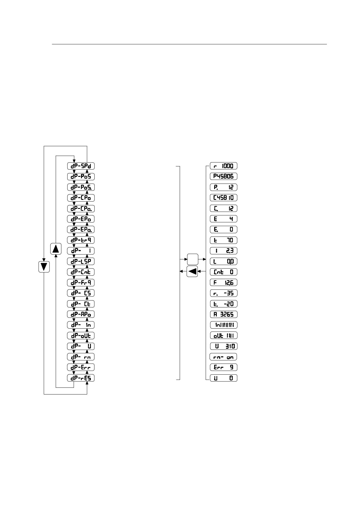
4.3 Monitoring Display(DP--)
Press the Up and the Down key to find the monitor display from the main menu.
When “dp-” is displayed, please press the Set key to enter the monitor mode. There are
19 kinds status for the monitor display, details shown in the following Diagram .Use Up
and Down key to select the display and press the Set key to enter the specific monitor
and display interface.
Feedback Speed(r/min)
Motor speed1000r/min
Feedback Position(Low)
Position 1245806 Pulse
Feedback Position(X100000)
Position Command(Low)
Command 1245810 Pulse
Position Command(X100000)
Position Error(Low)
Position Error 4 Pulse
Position Error(X100000)
Feedback Torque(%)
70% Rated Torque
Feedback Current(A)
Motor current 2.3A
Enter
Reserved
Reserved
Present Control Mode
Control mode 0
Pulse frequency(kHz)
Pulse frequency 12.6kHz
Speed Command(r/min)
Speed command -35r/min
Torque Command(%)
Torque Command -20%
Motor Current Position
Present Position 3265
Reserved
Reserved
Reserved
Reserved
Voltage of DC Bus
DC Bus Votage is 310V
Drive status
Status:Servo On
Error code
Error 9 occurs
Reserved
Diagram 4-3 The operational process of the monitor display
4.4 Parameter Setting(PA--)
Find the “PA-” on the main menu by using the Up and Down key, and then enter the
parameter selection interface by pressing the Set key. By using the Up and Down key
25
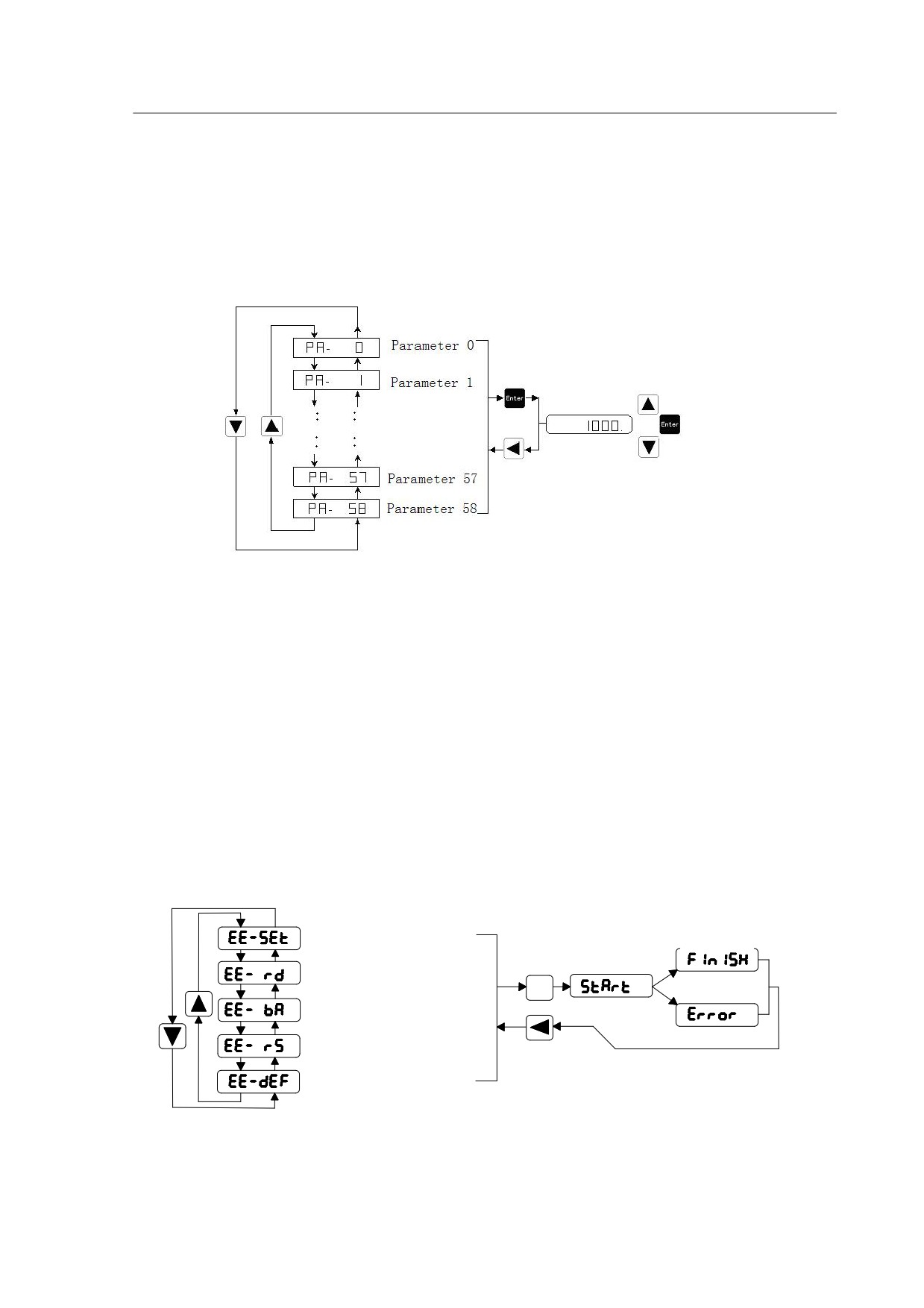
you can select the parameters according to your requirement, and then press the Set
key to enter the parameter modification interface. When the parameter is being
modified, the LED digital display is ON , that means you are in the process of changing
the parameters but they are not yet being activated. Press the Set key to save them and
the light will go off. Press the Return key to cancel the settings if required.
Diagram 4-4 Operation process of parameter settings
4.5 Parameter Management(EE--)
Find the “EE-” from the main menu by using the Up and Down key, and then enter
the parameter management interface by pressing the Set key. The functions and
descriptions of each symbol are shown in the Diagram 4-5. By using the Up and Down
key you can select the operations according to your requirement. Press and hold the
Set key for 3 seconds, when “FINISH” is displayed on the LED panel, it means the
operation is completed. But if it displays “Error”, it means the operation failed, please
press the Return key to cancel.
Parameter Write
Press for
Success
3 seconds
Parameter Read
Enter
Fail
Parameter Backup
Restore Backups
Restore Defaults
Diagram4-5 Operation process of parameter management
26
//////////////////////