Century Star HNC-180 series HNC-180xp/T3, HNC-180xp/M3, HNC-180GCE. Connection Manual (V2.0) - page 3
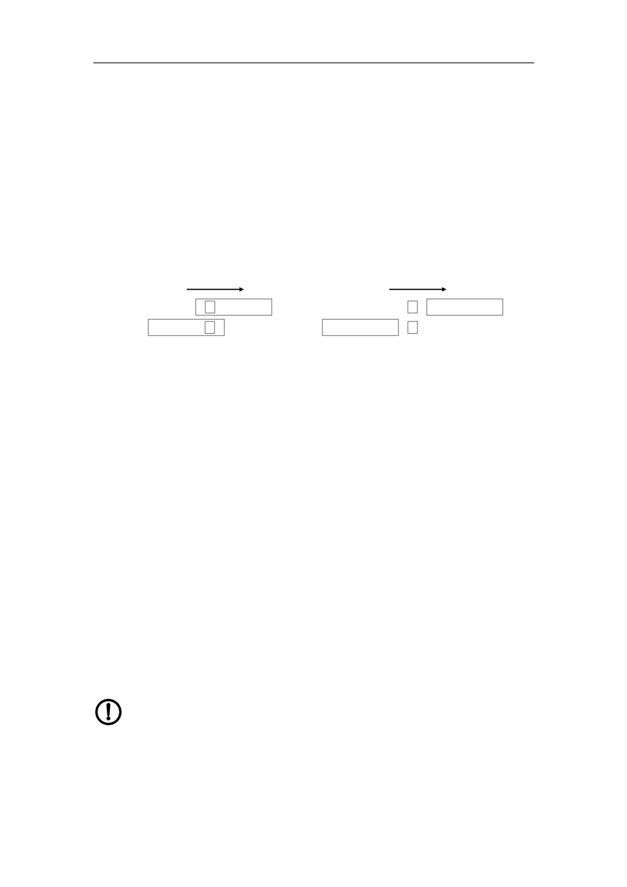
Note: There shall be a certain amount of overlap between the block for
reference point and the nearby over-travel limit switch to ensure that the
reference point return switch is not released, even if the over-travel limit switch is
pressed. Thus, the reference point return can be done correctly, when the
reference point switch just stops between the block of reference point and the
pressed over-travel limit switch. Figure 5-2 shows the installation of REF switch
and the over-travel limit switch. In the figure, ―A‖ means the block of reference
point, ―B‖ means the block of nearby over-travel limit, ―a‖ means the reference
point switch, and ―b‖ means the nearby over-travel limit switch.
REF direction
REF direction
b
B
b
B
A
a
A
a
(a) Correct Installation-overlap
(b) Incorrect Installation-without overlap
Figure 4-2 Installation of REF switch and over-travel limit switch
-
Check the effective travel range of each axis, and correctly set the positive
software limits, the negative software limits in axis parameters (the software limit
position is usually set between the two over-travel limit switches). Check the
validity of software limit protection after the reference point is returned.
4.4.4 Spindle Function
-
Check the direction and the speed of spindle rotation and set the related axis
parameters (in general, they are the transmission ratio of spindle transmission
part, the initial voltage/slope/the final voltage of D/A, the minimum speed, the
maximum speed etc.), to reach the running requirement of spindle.
-
Check other elements of PLC design, mainly including M, S and T commands, the
safety interlock relations etc.
4.4.4.1Spindle D/A
The output voltage of interface AOUT of spindle D/A is -10V~+10V.
Please set the type of speed command of spindle driver unit as the
voltage to connect with NC device, as the speed command of some
spindle driver unit can be in the form of both the voltage and current.
Otherwise, the related interface of spindle unit would be destroyed.
49
-
Ensure the related parameters of spindle D/A are correct.
-
Spindle parameter 007005
Theoretical maximum spindle motor speed in DA10V: the maximum spindle
analog voltage corresponding to motor revolution
-
Spindle parameter 007014
Minimum spindle DA(0-10V): the initial spindle analog voltage
-
Spindle parameter 007015
Threshold of spindle DA(0-10V): the threshold of spindle analog voltage
-
Spindle parameter 007026
Spindle ±10V: the range of spindle analog voltage
The voltage is 10V, when the spindle speed is the highest. For example, the
voltage is 0V if it is S0. If there is voltage deviation, spindle parameter 007014 and
007015 can be set to adjust the voltage offset compensation (generally, it has
been set in the production).
-
Check the parameters of the spindle frequency converter drive or spindle servo
drive.
-
Turn off the power supply and disconnect the cable plug connecting the NC device
with spindle frequency converter drive or spindle servo drive. Then, turn on the
power supply again. When NC device is just turned on, the output voltage of
spindle speed control signal AOUT (pin 1 and 2 of XS5) shall be around 9~10V.
When the system has completed the start-up, it shall be 0V.
-
Use the spindle speed control command (S command controlled by PLC program)
to set the spindle speed. Check the voltage variation of speed control signal
AOUT.
-
Turn off the power supply and connect the cable plug connecting the NC device
with spindle frequency converter drive or spindle servo drive. Then, turn on the
power supply again. Use the spindle speed control command (S command
controlled by PLC program) to set the spindle speed, and check the variation of
spindle speed.
-
Adjust the parameter setting of spindle frequency converter drive or spindle servo
drive to optimize their performance.
50
4.4.4.2Spindle Encoder
Encoder must be installed, if threading is required. The related parameters of spindle
with encoder are:
-
Spindle parameter 007027
Spindle encoder: spindle with/without encoder
-
Spindle parameter 010012
Spindle encoder revolution: the number of pulse per revolution of spindle sending
from the encoder to NC unit
-
Spindle parameter 001011
Spindle encoder direction: the direction of spindle encoder
The related parameters of spindle without encoder are:
-
Spindle parameter 007021
Spindle zero speed fluctuation: spindle zero speed status
-
Spindle parameter 007022
Error between command revolution and actual revolution: the error tolerance
between spindle command and actual revolution
4.4.4.3Spindle Brake
After M05 is executed, do set the proper spindle brake time to stop the spindle quickly
and increase the machining efficiency. When the motor is used to brake, too much
time consumed by brake would burn the motor out.
-
Spindle parameter 007023
spindle brake wait time: Interval time from receiving spindle stop command to
outputting brake signal.
-
Spindle parameter 007024
spindle brake continued time: the time to brake spindle
Note: If the spindle is equipped with a brake, do release the brake unit before
running the spindle.
4.4.4.4Spindle Gear
If the multi-speed motor is used to control machine, there are two gears of spindle:
-
Spindle parameter 007030~007037
Theoretical low speed and high speed of each gear: theoretical revolution range of
spindle gear
51
-
Spindle parameter 007038~007045
Actual low speed and high speed: actual revolution range of spindle gear
-
Spindle parameter 007046~007053
Numerator and denominator of transmission ratio: deceleration ratio of spindle
gear
When the programming revolution is different from the revolution detected by encoder,
the spindle parameters can be set to keep consistent. The method of setting
revolution is as followed: choose spindle 1st gear, input S in MDI to set parameters
007038~007045, monitor the spindle revolution, and input the checked values to
parameters 007038~007045. The setting methods of rest gear are same.
4.4.4.5Knife Rest Debugging
System supports different kind of knife rest. For the detailed parameter settings,
please refer to the machine’s manual. If the knife rest is 4-8 station power knife rest,
the cutter spacing signal is input directly, CW - tool selection, CCW - locked. The
related parameters of running knife rest are:
-
Knife rest and accessory parameters 007073
Check knife rest arrived signal: detect the knife rest arrived signal
-
Knife rest and accessories parameters 007018
Knife rest locked ready signal: detect the knife rest locked ready signal
-
Knife rest and accessories parameters 007008
Maximum time of switching tool: the maximum time to switch tool
-
Knife rest and accessories parameters 007009
Time of knife rest CW delayed: the delayed time from knife rest CW stop to CCW
locked start
-
Knife rest and accessories parameters 007007
Number of knife rest station: the number of knife rest station
-
Knife rest and accessories parameters 007010
Time of knife rest CCW locked: the time of knife rest CCW locked.
At the first time of switching tool, if the knife rest cannot rotate, it may be caused by
the wrong connection of phase sequence of three-phase power of knife rest. It should
press Reset key and cut off the power and check the wiring. If it is caused by the
wrong connection of the phase sequence of three-phase power, the operator can
switch two of three-phase power.
52
CCW locked time should be set properly. If the time is set too long, it would destroy
motor. If the time is too short, the knife rest would not be locked. The way to check the
lock of knife rest is: use the dial indicator to approach the knife rest, move the knife
rest manually, the fluctuation of point of dial indicator should not be more than
0.01mm.
In the debugging, each tool position and the maximum tool switch should change tool
once, monitor the validity of tool change and time parameters.
4.4.5 Machine Error Compensation
Please read section 4.3.6 Axis Compensation Parameters before setting the machine
error. Machine tool error compensation mainly includes the backlash and the pitch
error compensations, and these errors can be measured by the dial gauge, the block
gauge or the laser interferometer.
4.4.5.1Backlash Error Compensation
For the small machine, the pitch error compensation is usually neglected, while the
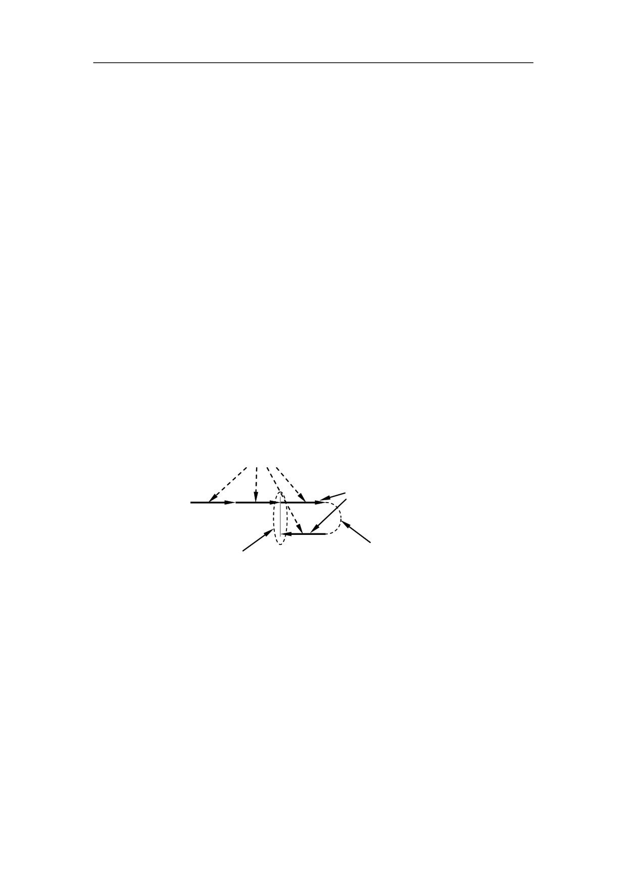
backlash is required to measure by using a dial gauge. The measurement is shown as
below:
G01command under MDI mode (not more than 1mm)
A
same tool movement
B
Reverse position
Reading data
Figure 4-3 Measurement of Backlash
Backlash error compensation (μm) = |A - B|; in which ―A‖ is the value read from the
dial gauge at position A, and ―B‖ is the value read from the dial gauge at position B.
Example: A=3mm, B=2.975mm, then,
Backlash error compensation=3-2.975=0.025mm=25μm
Note:
-
Set the backlash error compensation to 0 before the measurement.
-
Both backlash and pitch error compensation values can be measured by the laser
interferometer.
-
If the bi-directional pitch error compensation is used, then the backlash can be
omitted, as it can be done through the bi-direction pitch error compensation.
53
4.4.5.2Pitch Error Compensation
There are two kinds of pitch error compensation: unidirectional, and bi-directional.
The same offset for the positive and negative movement of feed axis is set in the
unidirectional compensation, while the different offset for the positive and negative
movement of feed axis is set in the bidirectional compensation. Generally, the
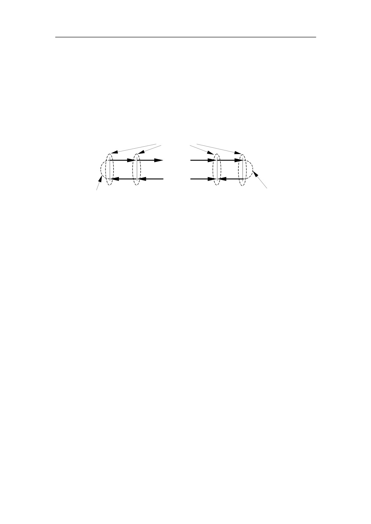
unidirectional pitch error compensation is used. The measurement is shown as below:
Reading data
A1
A2
An
An+1
……
……
B1
B2
Bn
Bn+1
Clear backlash
Clear backlash
Figure 4-4 Measurement of Pitch Error
A1~An+1: actual MCS position when the feed axis is moving in the positive direction;
B1~Bn+1: actual MCS position when the feed axis is moving in the negative direction;
Offset(μm)=Programming coordinate value in MCS-Actual coordinate value in MCS;
Please refer to section 4.3.6 for the program of measuring the pitch error.
In general, the offset interval is about 50mm.
Please set the offset parameters as 0 before the measurement of compensation.
Take axis Y for example, the related parameters and data are given as follows:
REF point position: 0 (axis parameter);
REF direction: + (axis parameter);
Pitch comp point interval: 50mm (axis compensation parameter);
Travel distance: 400mm (machine data)
Then, the measuring points are -400, -350, -300, -250, -200, -150, -100, -50, 0, in
which 0 is the reference point.
The actual value of measurement is as below:
-
negative direction:
-400.1,
-350.08,
-300.05,
-250.06,
-200.04,
-150.02,
-100.01, -50.005, 0;
-
positive direction: -400.15, -350.12, -300.1, -250.1, -200.07, -150.06, -100.04,
-50.05, 0.03;
Note: When the direction of reference point return is positive, the data at the
negative side is measured first.
54
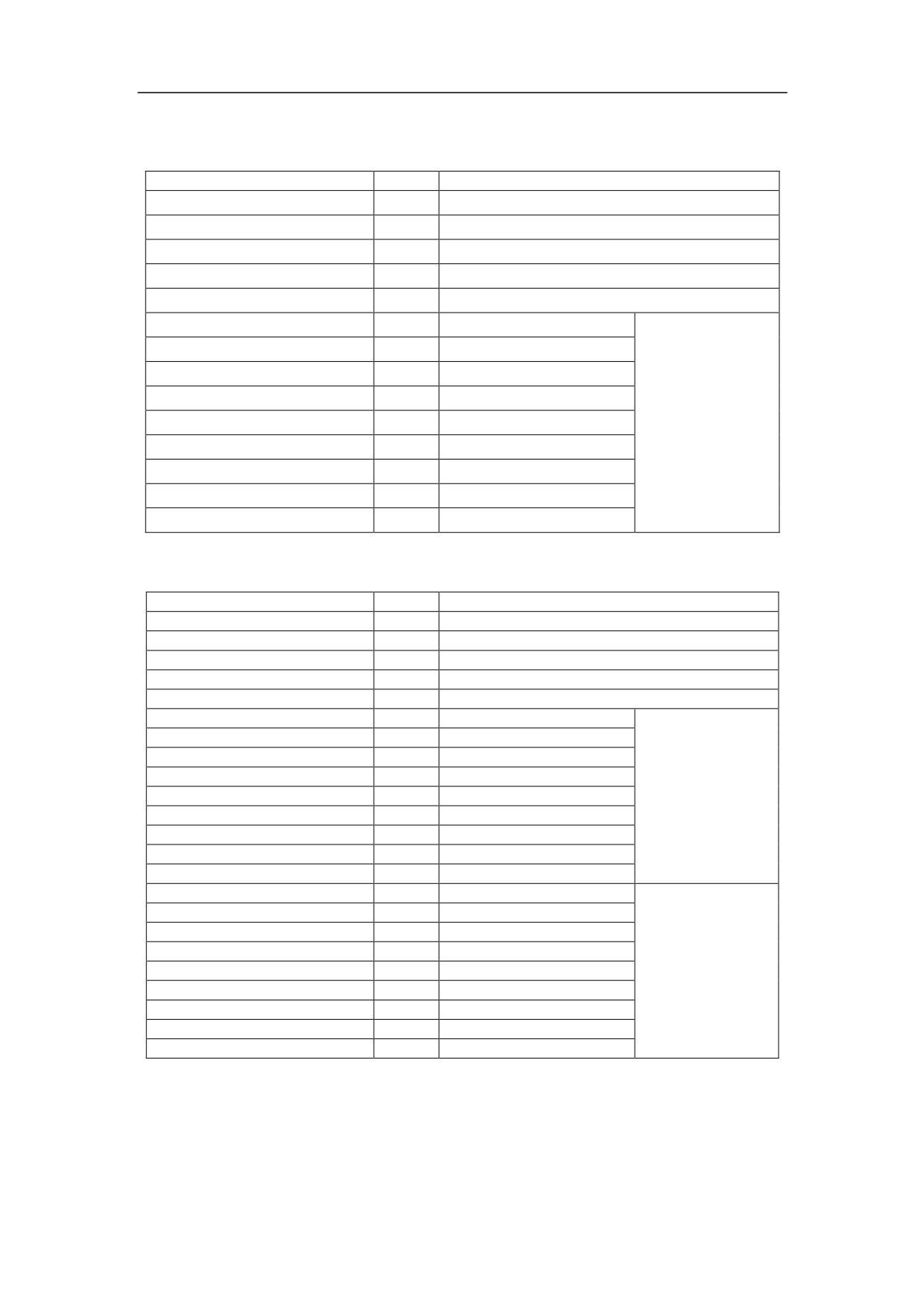
Therefore, the compensation parameters for axis Y shall be set as below:
-
Unidirectional pitch error compensation
Parameter Name
Value
Description
Backlash (μm)
30
Take -200 as the coordinate value
Pitch compensation type
1
Unidirectional pitch error compensation
Pitch compensation point
9
Index of REF point
8
Pitch comp point interval (μm)
50000
50mm
Offset (μm) [0]
100
(-400)-(-400.10)
Offset (μm) [1]
80
(-350)-(-350.08)
The data in the
Offset (μm) [2]
50
(-300)-(-300.05)
negative direction
are used.
Offset (μm) [3]
60
(-250)-(-250.06)
The offset for the
Offset (μm) [4]
40
(-200)-(-200.04)
reference point is
Offset (μm) [5]
20
(-150)-(-150.02)
usually zero, as
Offset (μm) [6]
10
(-100)-(-100.01)
REF point is at the
initial position.
Offset (μm) [7]
5
(-50)-(-50.005)
Offset (μm) [8]
0
(0)-(0) (reference point)
-
Bidirectional pitch error compensation
Parameter Name
Value
Description
Backlash (μm)
0
It is usually set as 0.
Pitch compensation type
0
Bidirectional pitch error compensation
Pitch compensation point
9
Index of REF point
8
Pitch comp point interval (μm)
50000
50mm
Offset (μm) [0]
150
(-400)-(-400.15)
Offset (μm) [1]
120
(-350)-(-350.12)
Offset (μm) [2]
100
(-300)-(-300.10)
Offset (μm) [3]
100
(-250)-(-250.10)
the data in the
Offset (μm) [4]
70
(-200)-(-200.07)
positive direction
Offset (μm) [5]
60
(-150)-(-150.06)
Offset (μm) [6]
40
(-100)-(-100.04)
Offset (μm) [7]
50
(-50)-(-50.05)
Offset (μm) [8]
30
(0)-(-0.03) (reference point)
Offset (μm) [9]
100
(-400)-(-400.10)
Offset (μm) [10]
80
(-350)-(-350.08)
Offset (μm) [11]
50
(-300)-(-300.05)
Offset (μm) [12]
60
(-250)-(-250.06)
the data in the
Offset (μm) [13]
40
(-200)-(-200.04)
negative direction
Offset (μm) [14]
20
(-150)-(-150.02)
Offset (μm) [15]
10
(-100)-(-100.01)
Offset (μm) [16]
5
(-50)-(-50.005)
Offset (μm) [17]
0
(0)-(0) (reference point)
Note: When the laser interferometer is used to measure the pitch error, it is necessary
to measure more than once. And the measurement software can automatically
calculate the offset data based on the groups of measured data. In order to keep the
precision of machine tool within specification, the offset data calculated in this way is
usually different from the data from the manual calculation.
55
5 Fault Diagnosis
5.1 Fault and Solution
5.1.1 Abnormal Start-up
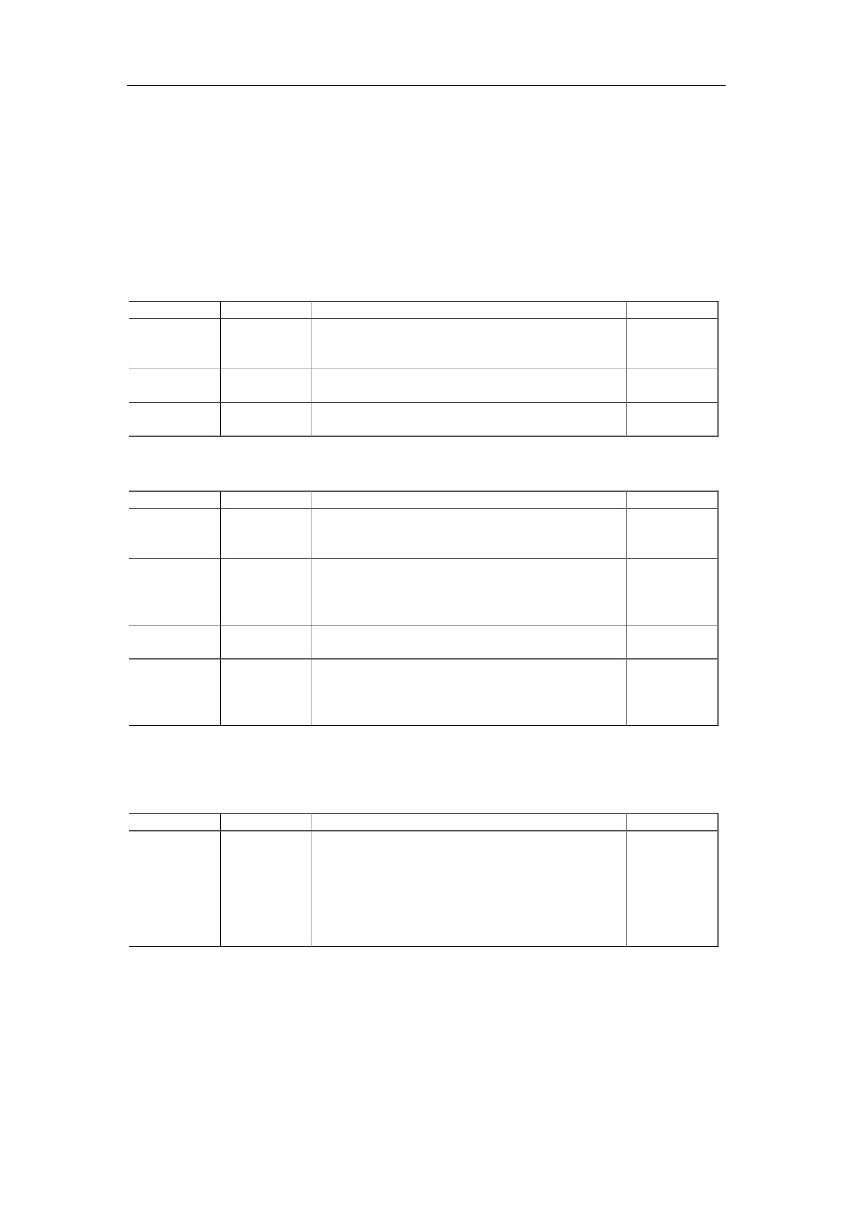
-
No Display
Category
Reason
Solution
Reference
incorrect
Check power supply socket;
Wiring
power
Check power supply: AC24V or DC24V;
Section 2.3
supply
Check wiring polarity;
too bright or
Adjustment
Adjust the knob on the back
too dark
mainboard
Hardware
Contact with us
error
-
System is crashed or restarted during the operation.
Category
Reason
Solution
Reference
Incorrect
Check parameters in E-stop mode after restart;
Parameter
setting of
Check axis parameters, PMC user parameters;
parameter
The parameter as denominator shall not be 0;
Reading
program
Wait for a moment;
Operation
from DNC
Stop the calling of the program;
or network
System
Software
Reinstall the system.
damaged
Check power supply socket;
Insufficient
Check the voltage of power supply;
Wiring
power
Section 2.3
Check the capacity of power supply;
supply
Check whether there is short circuit.
5.1.2 E-Stop and Reset
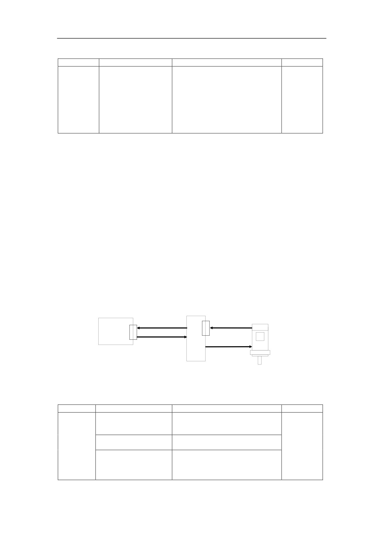
-
Unable to initiate reset signal
Category
Reason
Solution
Reference
Check the normal closed contact of over-travel
limit switch;
E-stop
Check the normal closed contact of E-stop
Hardware
circuit is not
button;
Section 3.5
closed
If the handheld unit is not used or there is on
E-stop button on the handheld unit, pin 4 and
17 of XS8 shall be short circuited.
56
-
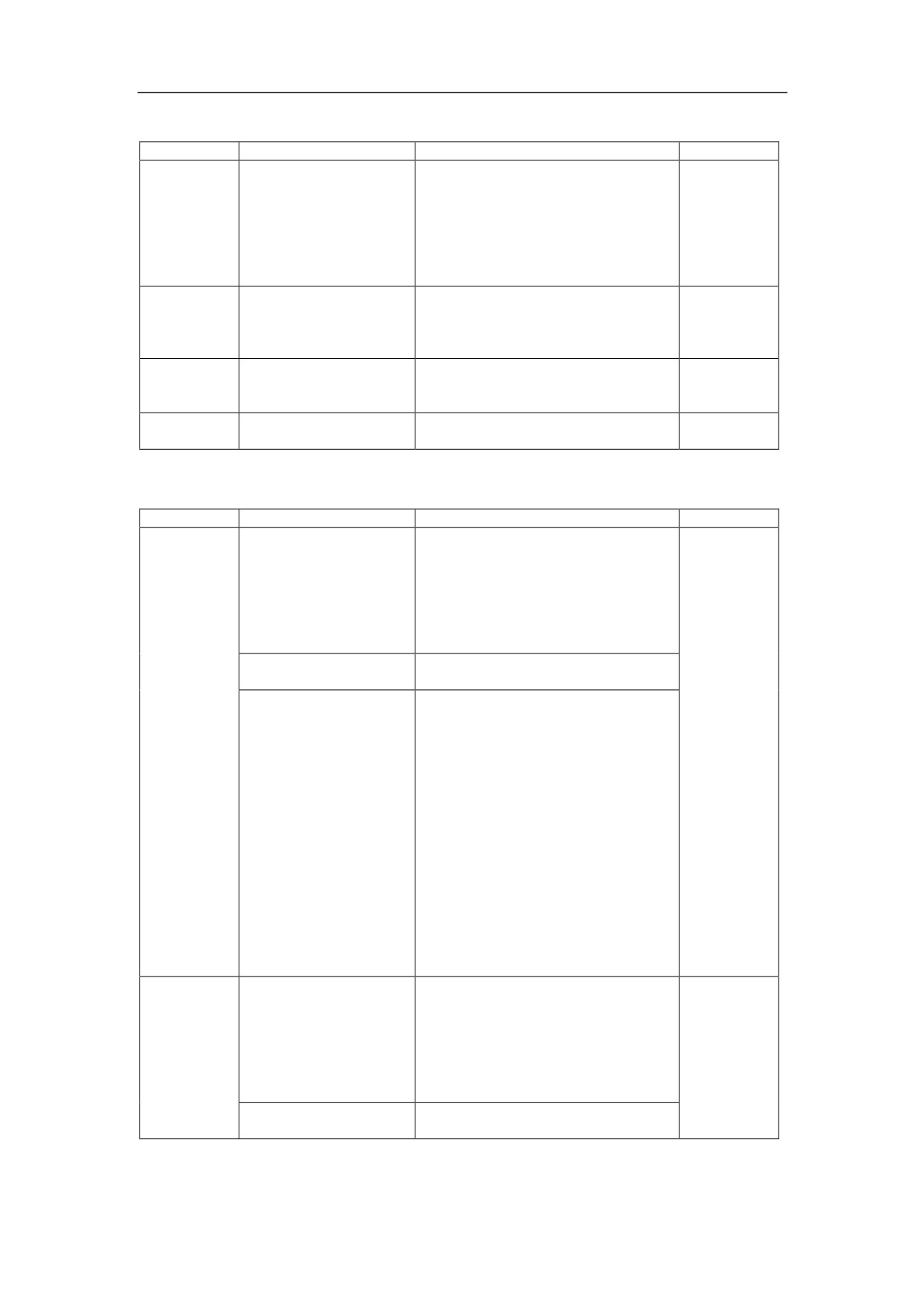
Fail to reset
Category
Reason
Solution
Reference
Check the logical circuit;
If HSV-20 servo is used, the reason
Requirement for reset
is usually the power supply of servo
is not reached, such as
drive is not ready; Check the power
Hardware
power supply of servo
supply module;
Section 3.1
is not ready, spindle
Check the wiring of power supply
drive is not ready etc
module;
Check air switch of servo drive
power supply.
5.1.3 Abnormal Running of Servo
The interchange method is frequently used to verify the faulty of servo, which
includes:
-
Interchange the motors connected to the servo drives;
-
Interchange the cables for servo drives;
-
Interchange the interfaces of HNC-180 used for servo drives.
Please turn off the power supply first, if adding or removing the cables or the
connectors is necessary to fix the problem. Please turn off the power supply for
three minutes and restart the system, after the parameters are modified.
Ensure the signal ground of feed drive unit or spindle drive is reliably connected with
the signal ground of NC device.
HNC-180
Servo driver
Servo motor
XS1~3
Position FB cable
Position FB cable
(Encoder cable)
Axis control cable
Heavy current cable
of servo
Figure 5-1 Connection between HNC-180 and Servo unit
-
There is an alarm message, once the power supply of servo drive is on.
Category
Reason
Solution
Reference
Error in phase order of
Check the phase order of servo
servo motor strong
motor
current cable
Connection error in
Check the position feedback cable
Section
Wiring
position feedback cable
4.1.1
Position feedback cable
is not corresponding to
Check the motor wiring
motor strong current
cable
57

-
Servo motor is dithering when it stops
Category
Reason
Solution
Reference
Error in the wiring of
Wiring
position feedback
Check the position feedback cable
Section
cable
4.1.1
Abnormal running
Motor
Check servo motor and servo drive
of motor encoder
Check the parameters related to gain
adjustment of servo drive, and adjust
Error in the
them carefully.
Parameters
parameter
Proportion coefficients and integration
time of speed loop can be reduced
properly.
-
Servo motor rotates slowly with zero drift.
Category
Reason
Solution
Reference
Servo drive is set to be controlled by
the external command.
Check the consistency between the
Operational
Error in parameter
Parameter
internal control mode of servo drive
manual of
of servo drive
and the actual condition. Example: For
Servo drive
the drive with pulse interface, it is set
as position control mode.
Error in the servo
Setting of servo type shall match with
Parameters
parameters
the actual condition
Weak connection of
axis control cable
Check the axis control cable
(XS1,
Section
Wiring
between NC unit
XS2, and XS3)
4.1.1
and Servo drive
Make coordinate axis control cables
shielded with reliable grounding;
Interference to the
Do not twist, if possible;
Wiring
Section 3.5
axis control cable
Keep the strong current cables as far
possible;
Do not lay with them in parallel.
-
Servo motor does not rotate.
Category
Reason
Solution
Reference
Disconnected
Check the strong cable of motor;
control cable
Check the control cable of axis;
Section
Wiring
No servo power
4.1.1
Check the power supply of servo;
supply
Error in the
The internal parameter of servo drive
Parameters
parameter of servo
shall be set as the external command
drive
control, i.e. controlled by NC device
Check if servo drive can correctly
Error in the servo
receive the enabled signal;
Parameters
parameter
Check the servo type of servo
parameters in NC device;
Check the consistency between the
Error in machine
Parameters
pulse type of NC unit and the setting of
parameter
servo drive.
Press the machine locked button to
Operation
Machine is locked
release the locked status.
Motor rotation
Check if brake on motor is on;
Installation
blockage
Check if mechanical load is too much.
58
-
Motor can only rotate a short distance.
Category
Reason
Solution
Reference
Check if the position feedback cable
is corresponding to the motor strong
Wrong connection
current cable;
between the position
Section
Wiring
Check the phase order of motor
feedback cable and
4.1.1
strong current cables;
strong cable of motor
Check if the position feedback cable
is disconnected.
Set the correct motor revolution;
Error in the servo
For the servo with pulse interface,
Parameters
parameter
E-gear(NC)/E-gear(Servo) shall be
set correctly.
Error in the setting of
Parameters
motor pole pairs of
For GK motor, it is set as 3.
servo drive
Too much mechanical
Check if the mechanical load is too
Installation
load
much
-
Motor jitters when rotating.
Category
Reason
Solution
Reference
Ground the whole system as
required;
Each unit or device shall be
No reliable grounding
grounded reliably;
Signal ground of drivers and NC
device shall be reliably common
grounded.
No reliable power
Check the connection of servo drive
supply of servo drive
power supply control circuit;
Position feedback cables and axis
control cables must be shielded
cables with reliably grounding;
Wiring
In the position feedback cable, the
Section 3.6
power supply wire and its ground
wire shall be thicker. Two or three
wires are connected in parallel;
The length of axis control cables or
Interference
position feedback cables shall be
within 15m;
The axis control cables and position
feedback cables must be laid
separately from the strong current
cables;
Do not twist axis control cable and
position feedback cable, if possible.
Check if the motor strong current
cable is corresponding to the
Wrong connection of
position feedback cable;
encoder cable and
Check the phase order of motor
motor power supply
Section
Wiring
strong current cables;
cable
4.1.1
Check if the encoder cable is
disconnected.
Disconnected position
Check and repair the position
feedback cables
feedback cables
59

Check the parameters of servo
drive, and run the motor by using
servo internal command to verify
the correctness of parameters.
Then, connect to NC device.
Check the parameters related to
Operational
Error in the parameter
Parameters
gain adjustment of servo drive, and
manual of
of servo drive
adjust them carefully.
Servo drive
Proportion coefficients and
integration time of speed loop can
be reduced properly.
Use GK servo motor, and set the
pole pairs of motor as 3.
Uneven mechanical
Installation
Check the mechanical load
load
Motor
Motor encoder broken
Repair or Replace the motor
-
Motor is creeping
Category
Reason
Solution
Reference
No reliable motor
Check motor strong current cables;
Wiring
Section 3.6
grounding
Check the axis control cable
Mechanics
Too much load
Check the servo power supply
Check the parameters related to
gain adjustment of servo drive, and
Operational
Error in the parameters
adjust them carefully.
Parameters
manual of
of servo drive
Proportion coefficients and
Servo drive
integration time of speed loop can
be reduced properly.
-
Incorrect motor positioning and Accumulative Error
Category
Reason
Solution
Reference
Check the motor strong current
No reliable motor
cables;
grounding
Check the axis control cable
Use the shielded cable or
twisted-pair double shielded cable
with good quality;
Use the thicker power supply wire
Wiring
Section 3.6
for position feedback cable, such as
No reliable position
take several wires connected in
feedback cable
parallel;
Shield layer of cable is grounded
reliably;
Add the magnetic rings on both
sides of cable.
Unreliable mechanical
Mechanics
Adjust the mechanical connection.
connection
Motor
Motor encoder broken
Replace the motor
-
Weak torque output from motor axis
Category
Reason
Solution
Reference
No reliable motor
Check motor strong current cables;
Wiring
grounding; being
Check the position feedback cable;
Section 3.6
interfered
Check the axis control cable;
Motor
Motor encoder broken
Replace the motor
60

-
Driving axes slips down when starting
Category
Reason
Solution
Reference
No balancing device;
Add a balancing device;
Mechanics
Invalid balancing unit
Check the balancing device;
Too early brake from
Check if the connection of X0.2
Wiring
the motor
(axis Z ready) is correct.
-
Reference point return error
Category
Reason
Solution
Reference
Check if the parameter - stepper
It automatically stops
motor pulses - is set.
Parameters
when reference point is
Check the setting of the parameter
positioning.
- motor revolution. It shall be pulses
from servo to NC unit*4.
5.1.4 Abnormal Frequency Converter and Servo Spindle
-
Spindle overspeed and uncontrollable
Category
Reason
Solution
Reference
Check the setting of spindle drive;
Error in the setting of
Parameters
Spindle drive should be controlled
spindle drive
by the external command.
Speed control signal cables shall be
shielded cables with reliable
grounding;
A resistance of 500-1000 ohms and
Section 3.2
Wiring
Interference
ceramic plate capacitance of 1000p
Section 3.6
shall be connected to the spindle
drive side of speed control signal
cables in parallel.
Hardware
D/A circuit faulty
Repair or replace NC unit
-
Failed pitch machining
Category
Reason
Solution
Reference
Check the consistency between the
Error in the direction of
Parameters
spindle encoder direction and the
spindle encoder
actual direction of spindle rotation.
-
Incorrect pitch machining
Category
Reason
Solution
Reference
Error in the setting of
Parameters
Check the spindle revolution
spindle revolution
Replace spindle encoder. Turn the
spindle manually and monitor the
Spindle encoder faulty
spindle speed to check whether the
Mechanics
encoder is damaged.
Spindle encoder
Repair or replace
coupling faulty
Check the power supply of spindle
encoder. If it is higher than the
Not enough power of
output capacity of XS9 of HNC-180,
Hardware
Section 3.2
spindle encoder
the independent power supply with
DC5V for spindle encoder shall be
used.
61

5.1.5 Abnormal Running of I/O
Note: Each DC solenoid valve and brake must be connected to damper diode.
Otherwise, the performance of DC24V power supply would be affected by the current
shock when the solenoid valve is turned on. This would cause the random alarms
from NC device or servo drive.
Each AC contactor and AC asynchronous motor such as cooling motor, hydraulic
motor and AC asynchronous spindle motor controlled by contactors must be
connected to RC arc damper. Otherwise, the performance of AC power supply would
be affected and the interference would be produced by the current or voltage surge at
the instant of turning on these devices. This would cause the random alarms from NC
device or servo drive.
-
No input or output signal
Category
Reason
Solution
Reference
DC24V power supply for external
on-off I/O must have common
Signals without
Wiring
ground with DC24V power supply
Section 2.3
common grounding
for HNC-18i/18xp NC unit through
XS6 and XS9.
-
Unstable I/O
Category
Reason
Solution
Reference
It is recommended to use the
independent shielded cables for
connecting on-off input and output
signals with reliable grounding,
when separating HNC-180 device
Wiring
Interference
Section 3.6
and strong current cabinet;
The length of cable wire shall be
within 15m;
HNC-180 NC device shall be
grounded reliably.
Check the input/output voltage of
Wiring
Abnormal power
Section 2.3
HNC-180 NC unit
Too much interference
Check the anti-interference circuit of
from other devices
this kind of devices. For example,
Section 2.3,
Wiring
sharing DC24V power
check the damper diodes in the
Section 3.6.
supply with PLC
band brake and the solenoid valve.
62
5.2 Alarm Messages
Please stop running the machine and check the alarm messages to fix the problem,
once there is abnormal running.
5.2.1 Check Alarm Messages
The operator press
DGN function key and
F3 soft key to check the alarm messages.
When a fault occurs, CNC system will give an alarm message. For more detailed
information, please refer to the operator’s manual.
The alarm messages are categorized into the internal alarm and external alarm, in
which the internal alarm is categorized into the programming error and the hardware
error. In this manual, only the internal alarm messages related to hardware error
would be described, which includes the error number and the alarm message. The
external alarm messages are controlled by PLC. For detailed information, please refer
to the operation manual of HNC-180 PLC.
The alarm message of common error would not be shown, once the problem is fixed.
For the alarm message caused by E-stop, the alarm message would not be shown
only if RESET button is pressed. Some alarm messages, such as the alarm caused
by the setting of hardware parameters, would not be shown unless the system is
restarted.
63

5.2.2 List of Alarm Messages
No.
Alarm Message
System status
Solution
Initialization
Set the axis parameters and servo
01h
Emergency stop
Error
parameters correctly.
02h
Parameter Error
Emergency stop
Set the parameters correctly.
05h
Position Lost
None
Move the axis
Check the parameter, wiring and power
09h
Unknown Error
Emergency stop
supply, and turn on power supply again.
Positive
No axis
Press the over-travel released button, move
20h
overtravel
movement
the axis to the negative direction.
Negative
No axis
Press the over-travel released button, move
21h
overtravel
movement
the axis in the positive direction.
the overtravelled
Positive
axis stops moving
22h
Move the axis to the negative direction.
software limit
to the positive
direction
the overtravelled
Negative
axis stops moving
23h
Move the axis to the positive direction.
software limit
to the negative
direction
Turn on the power again, after it has been
30h
Hardware Error
Emergency stop
off for three minutes.
Abnormal
Check the position feedback cable of
38h
Emergency stop
feedback
HNC-180 NC unit.
Check the axis control cable of servo drive.
40h
Overspeed
Emergency stop
Set the value of maximum feedrate higher.
Check the mechanical load;
Check the power supply of servo drive;
Check the brake of servo;
Tracking error
Check if the rapid traverse speed is higher
41h
Emergency stop
too much
than the rated motor rotation speed;
Check the internal parameter of servo drive;
Check the motor revolution;
For servo, check E-gear(NC)/E-gear(Servo)
Check the reference point switch;
No reference
44h
Emergency stop
Check the encoder feedback cable;
point return
Check the zero (Z, /Z) pulse of encoder;
64
6 Example of Typical Design
6.1 Overview
Applications of HNC-180 NC device to various NC machine tools may be different
chiefly in two ways:
-
Different feed axis
It is specified in section 3.1.
-
Different electrical design
It would be described in this chapter.
65

6.2 Example of Design
6.2.1 Brief Introduction
-
Machine: 2-coordinate parallel lathe, with 4-position automatic cutter saddle;
-
Structure of control cabinet: strong current control cabinet + operation station
-
Spindle: frequency converter + normal asynchronous motor
The following table shows the main components in the design of NC turning system.
Table 6-1 Main components in the design of NC turning system
No.
Name
Specification
Description
Notes
1
NC device
HNC-180xp/T3
Control system
HCNC
2
Handheld unit
HWL-1013-3
Manual control
HCNC
Power supply for servo
control, Power supply for
AC380/220V 250W
switch
Control
3
/110V 150W
Power supply for heat
HCNC
transformer
/ 24V 100W
exchanger and AC
contactor
Power supply for spotlight
Servo
Power supply servo supply
4
3P AC380/200V 2.5KW
HCNC
transformer
module
Switch power
5
AC220/DC24V 35W
I/O and intermediate relay
Ming Wei
supply
6
Servo driver
HSV-160B+-030
Axis X/Z motor drive
HCNC
7
Servo motor
130ST-M06025LFB(6NM)
Axis X feed motor
HCNC
8
Servo motor
130ST-M07720LFB(7.5NM)
Axis X feed motor
HCNC
Frequency
Spindle frequency
9
SJ300-075HF
Yaskawa
converter
converter
66
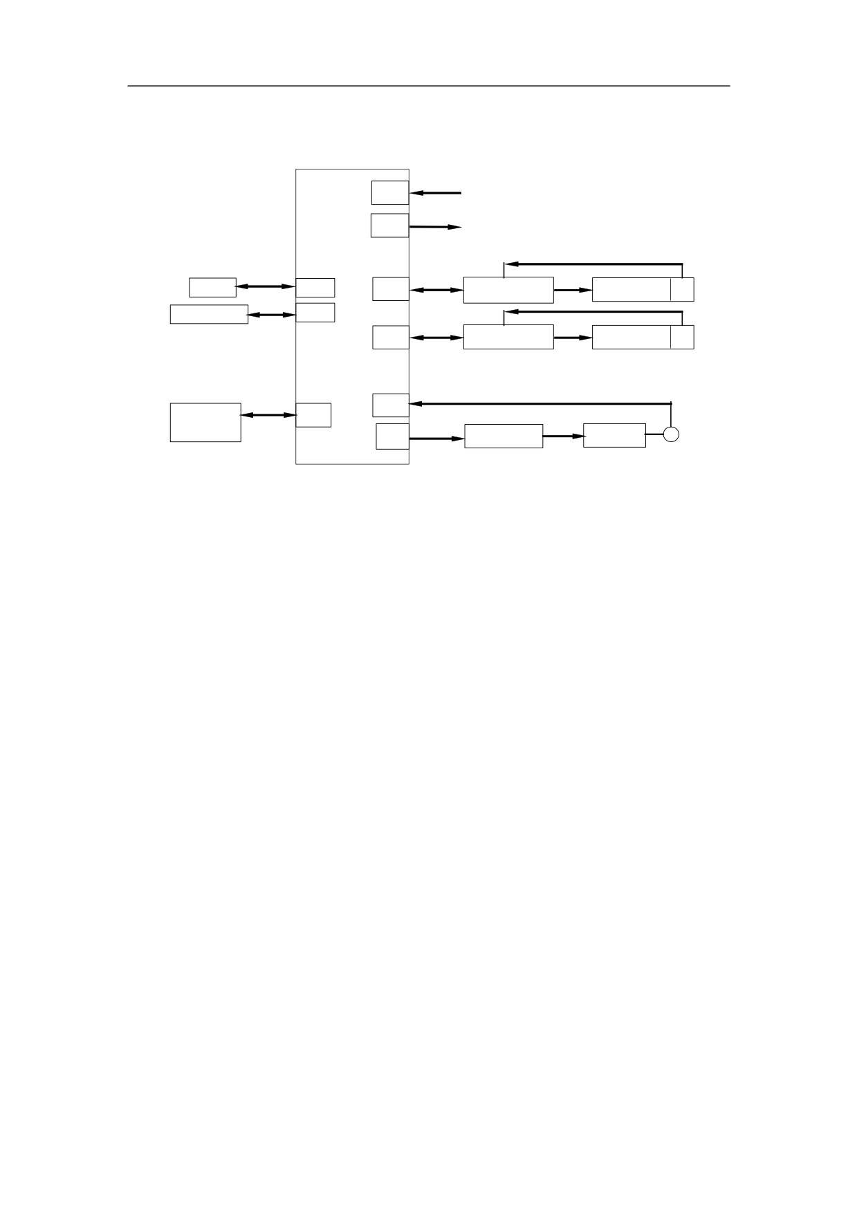
6.2.2 Overall Diagram
XS6
On-off input (machine inspection)
XS9
On-off output (controlled by relay)
HNC-180xp/T3
Encoder on Axis X
USB
XS12
XS1
HSV-160B+ servo X
Servo motor X
PC keyboard
XS10
Encoder on Axis Z
XS3
HSV-160B+ servo Z
Servo motor Z
XS4
Handheld
XS7
unit
XS5
SPDL f.converter
SPDL motor
Encoder
Figure 6-1 Overall Diagram of Typical Design of NC Milling System
6.2.3 I/O Specification
For detailed information, please refer to Chapter 3.
6.2.4 Circuit Diagram
The following section describes the main parts of the circuit diagram. As to the wire
number, only those appeared in different pages are given.
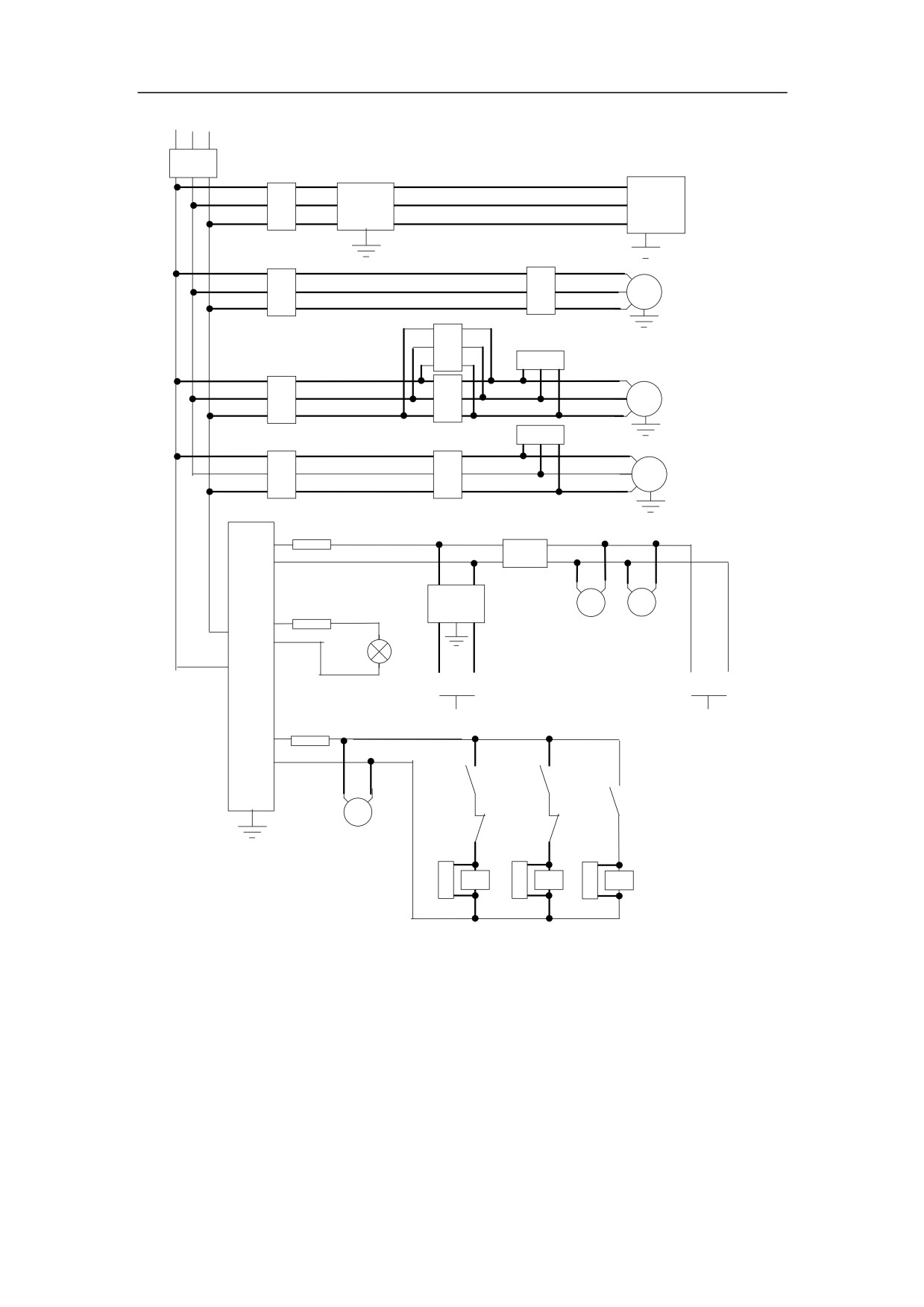
6.2.4.1Connection to Power Supply
There is no solenoid valve in the system. Only one power supply with DC24V 35W is
used. A low pass filter is used at the lead-in wire of switch power supply to separate
from the power supply of servo(AC220V)
In Figure
7-2, QF1~QF5 are 3φ air switches. QF6~QF8 are 1φ air switches.
KM1~KM3 are 3φ AC contactors. RC1 and RC2 are 3φ RC absorbers (arc damper).
RC3~RC5 are 1φ RC absorbers (arc damper). KA1~KA3 are DC24V relays.
Note: The magnetic rings and the high voltage ceramic plate capacitors at the main
power lead-in wire and the transformer input side are not shown in this figure.
67
AC380V 3φ
QF1
Servo Transformaer
32A
R
QF2
AC380/220
Servo
S
HSV-160B
+
10A
2.5KW
T
X,Z
U11
Spindle frequency converter
QF3
V11
Spindle
20A
5.5KW
W11
motor
KM2
RC1
QF4
KM1
Knife rest
0.4A
motor
RC2
QF5
KM3
Coolant
1A
motor
Lowpass filter
QF6
AC220V
AC250V
3A
300W
6A
Power supply
AC220V/
QF7
35W
DC24V
AC24V
Suspension fan
6A
AC380V
100W
500W
Spotlight
24V
100
220A
220B
To: Relay
QF8
To: NC unit
AC110V
Servo
23A
100W
KA1
KA2
KA3
KM2
KM1
Cabinet fan
Control
RC3
RC4
RC5
transformer
KM1
KM2
KM3
Knife rest Knife rest Coolant
motor CW
motor CCW
Motor
Figure 6-2 Circuit diagram of typical turning system - power supply
68
6.2.4.2Connection to Relay and I/O
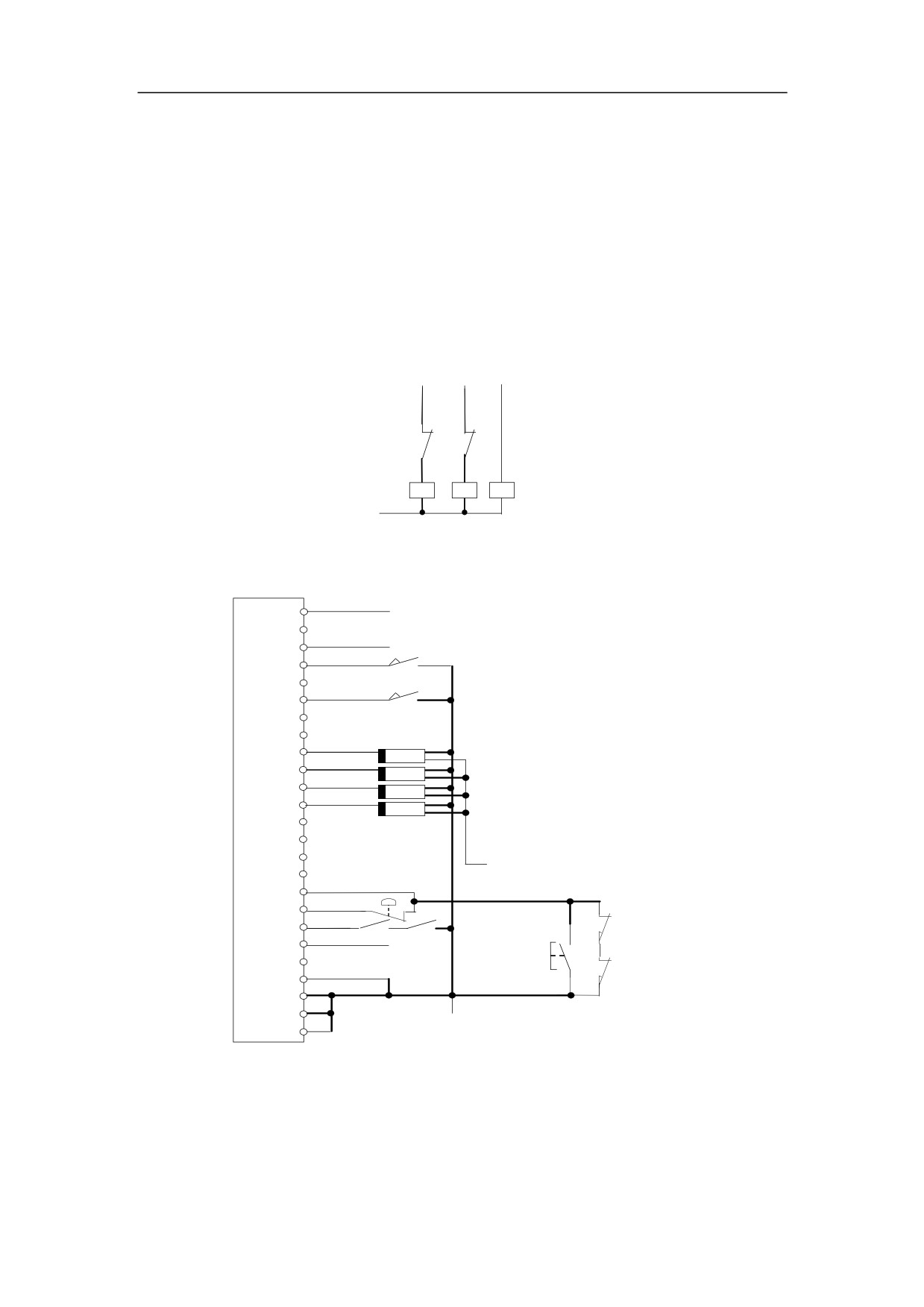
Relay is controlled by the on-off output signals, and the on-off input signals mainly
refer to the status and alarm messages of feed unit, spindle unit, machine tool electric
part etc.
As it is shown in Figure 7-3, KA1~KA3 are intermediate relays.
Knife rest
Knife rest
Coolant
CW
CCW
Start
Y1.0 Y1.1 Y1.2
KA2
KA1
24V
KA1
KA2 KA3
Figure 6-3 Circuit diagram of typical turning system - Relay
XS6
X0.0
13
25
X0.2
12
X0.3
SQX-2
24
REF switch on Axis X
11
SQZ-2
X0.5
23
REF switch on Axis Z
10
22
X1.0
SQ1
9
Tool-1 Ready
X1.1
SQ2
21
Tool-2 Ready
X1.2
SQ3
8
Tool-3 Ready
X1.3
SQ4
20
Tool-4 Ready
7
Hall Switch
19
6
24V
18
X2.0
5
Overtravel input
X2.1
17
QF5
E-stop input
X2.2
QF4
4
External alarm
SQX-1
X2.3
16
Overtravel
3
released button
SQZ-1
X2.5
15
2
14
Axis overtravel limit switch
100
1
(Relay DC24VG)
Figure 6-4 Circuit diagram of typical turning system - I/O 1
As it is shown in Figure 6-4, X0.0~X0.2, X1.1, X1.2, and X2.3 are from XS1~XS3
(feed axis interface), and XS5 (spindle interface). If there is no related alarm input
signals, then the corresponding input signals shall be connected to DC24VG. ―100‖
69
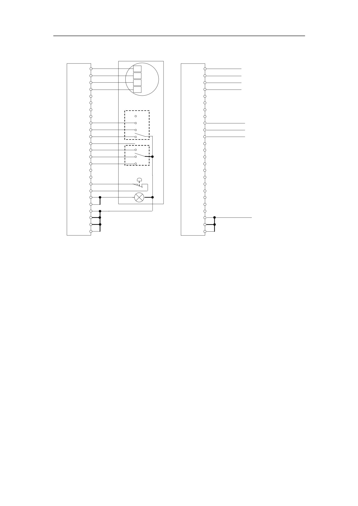
and ―24V‖ in the graph is the output of DC24V 35W switching power supply.
XS7
XS9
5VG
Y0.0
13
5VG
13
+5V
Y0.1
25
+5V
25
Y0.0~Y0.3 are from
HB
MPG
Y0.2
12
B
12
XS1~XS3 and XS5.
HA
Y0.3
24
A
24
11
11
23
23
Axis
10
10
OFF
22
22
X3.0
X
Y1.0
9
9
Turret motor CW
X3.1
Y
Y1.0
21
21
Turret motor CCW
X3.2
Z
Y1.2
8
8
Coolant relay
X3.3
20
20
X3.4
X1
7
7
X3.5
X10
19
19
X3.6
X100
6
6
Override
18
18
5
5
E-Stop
24VG
17
17
4
X3.7
4
16 +24V
+24V
Pilot
16
3 +24V
3
15 24VG
24VG
15
2 24VG
Handheld unit
2 24VG
100
14 24VG
(Relay DC24VG)
14 24VG
1 24VG
1 24VG
Figure 6-5 Circuit diagram of typical milling system - I/O 2
70
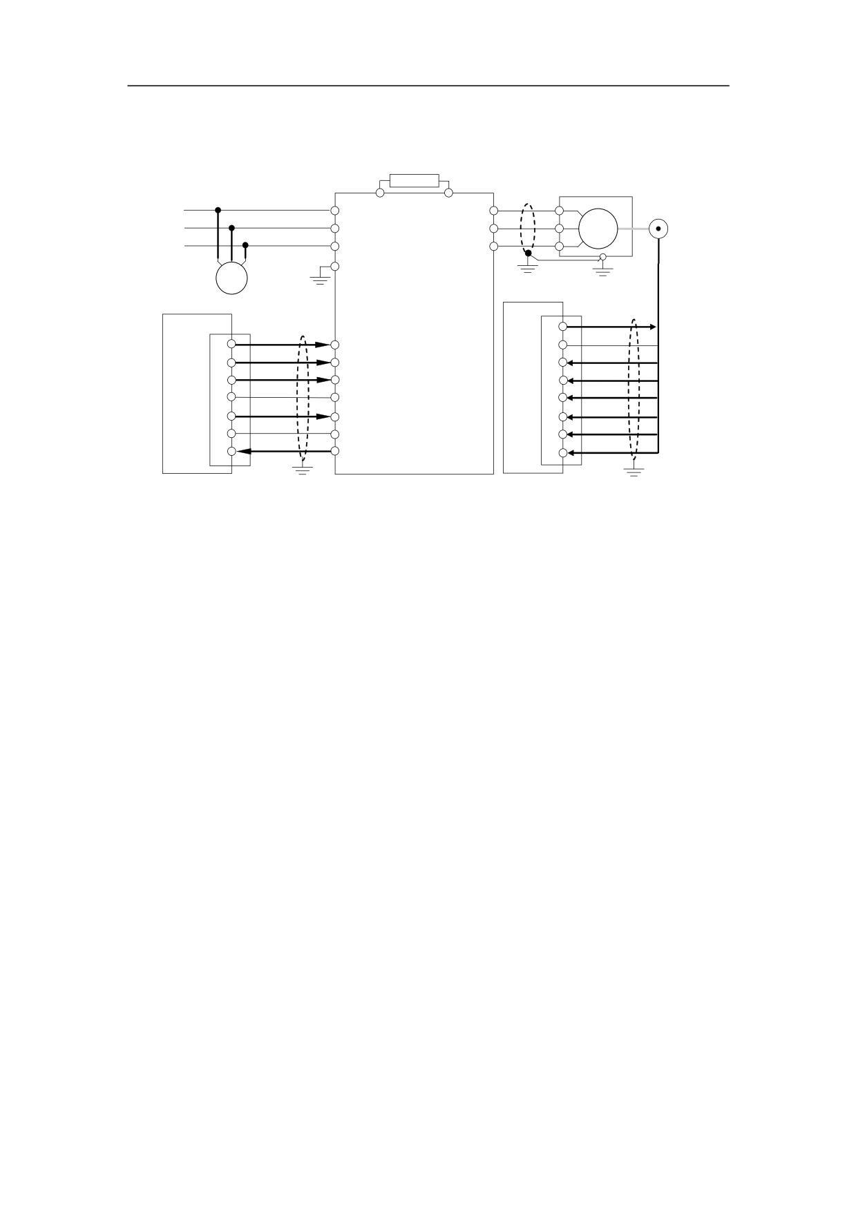
6.2.4.3Connection to Spindle
Brake RC
50Ω 1000W
Spindle motor
B1
B2
U
Spindle encoder
U11
R(L1)
U(T1)
V
V11
S(L2)
V(T2)
5.5KW
W
W11
T(L3)
W(T3)
From KM2
Spindle frequency
(Figure 7-2)
converter
HNC-18xp/T
Spindle fan
SJ300-075HFE
XS6
7.5KW
+5V
XS5
1
Y0.2
5VG
25
FW
Spindle CW
5,6
Y0.3
SA+
24
8
Spindle CCW
2
+24V
SA-
14
PLC
+24V
7
100
SB+
24VG
9,15
AL0
3
DAS+
SB-
AOUT
1
O
8
DAS-
SZ+
2
L
4
X2.3
SZ-
20
AL1
Spindle alarm
9
HNC-180xp
Figure 6-6 Circuit diagram of typical turning system - Spindle
71
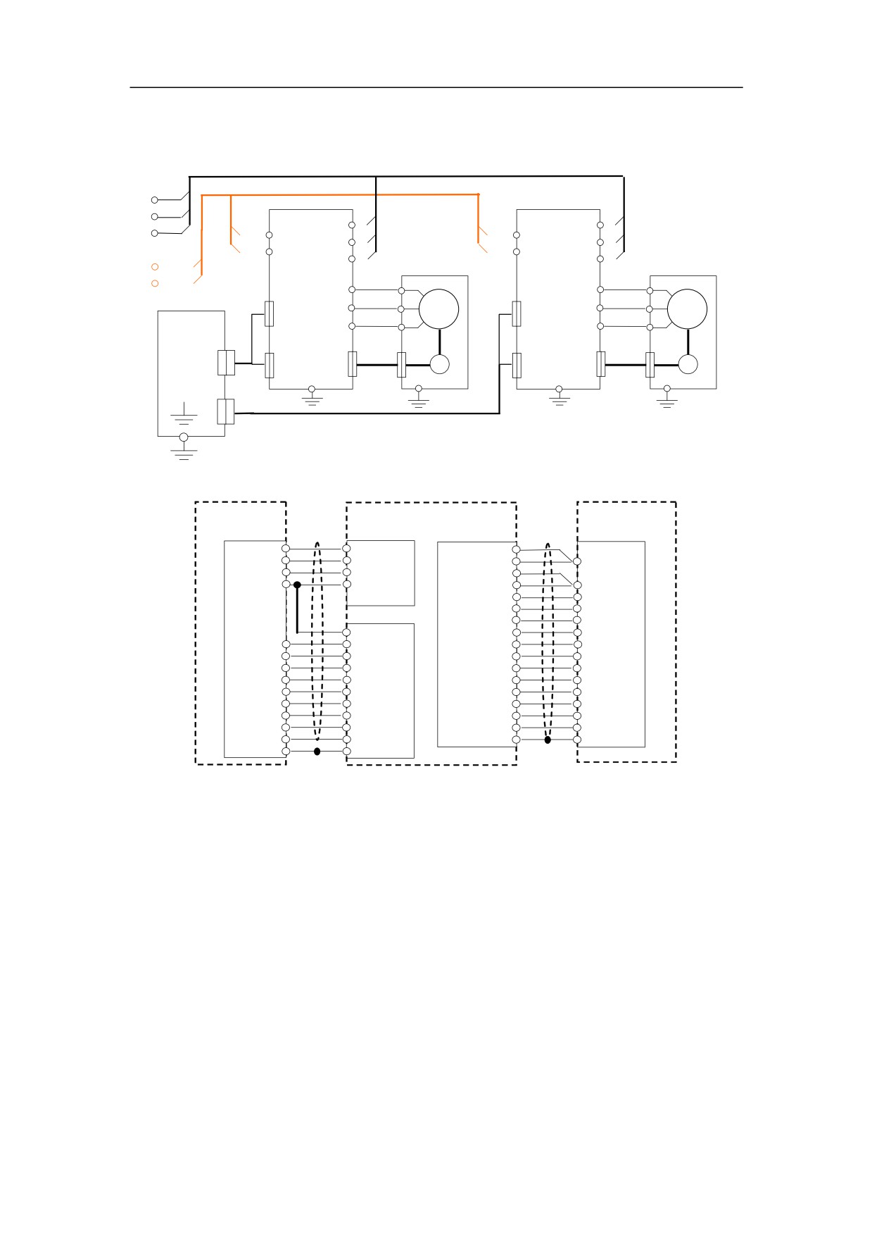
6.2.4.4Connection to Servo Drive Unit
R
S
R
R
Axis X
R
Axis Z
R
T
220A
220A
AC1
S
AC1
S
S
S
220A
220A
AC2
T
AC2
T
220A
T
Axis X
T
Axis Z
HSV-160B+
HSV-160B+
220B
UX
2
UZ
2
U
U
XS3
XS3
V
VX
4
V
VZ
4
CMD signal
CMD signal
WX
3
WZ
3
NC unit
W
W
XS1
XS4
XS4
XS2
XS
XS2
XS
Encoder
Encoder
HNC-180xp
I/O
Encoder
PG
I/O
Encoder
PG
Cables
Cables
PE
PE
XS3
Figure 6-7 Circuit diagram of typical turning system - Servo Drive Unit
HNC-180xp/T3
HSV-160B+
ST motor
XS1,3
COMMAND
ENCODER
XS
Y0.1
4
1Enabled
+5V 16,17
Y0.0 12
2Reset
+5V 18,19
12 +5V
X0.*
5
8Ready
5VG 23,24
GND 13
19 24VG
13 GND
+24V 6
A 1
2
A
B 3
4
B
*:0,1,2
Z 5
16 Z
23,24 GND
U 7
6
U
A+
1
32 A+
V 9
8
V
A-
9
33 A-
W 11
10
W
B+
2
18 B+
/A 2
3
/A
B- 10
36 B-
/B 4
5
/B
Z+
3
35 Z+
/Z 6
17 /Z
Z- 11
34 Z-
/U 8
7
/U
CP+ 14
14 CP+
/V 10
9
/V
CP-
7
15 CP-
/W 12
11 /W
DIR+ 15
16 DIR+
PE 14,15
1 PE
DIR-
8
17 DIR-
Axis control cable
Axis encoder cable
Figure 6-8 Circuit diagram of typical turning system - Servo drive cable