Century Star HNC-180 series HNC-180xp/T3, HNC-180xp/M3, HNC-180GCE. Connection Manual (V2.0) - page 2

3.2.9 Parameters related to Spindle device
The digital value relevant to spindle speed control signal takes two bytes, i.e. 16 bits,
of PLC output Y[28] and Y[29] (Y[29] takes higher 8 bits). The relationship between
output (digital value) and its relevant analogue voltage is shown below:
Table 3-8 Relationship between output and analog voltage
OUTPUT (HEXADECIMAL)
-0x7FFF~+0x7FFF (-32767~+32767)
AOUT
-10V~+10V
There are two kinds of parameter related to spindle device:
1. Spindle speed analog voltage
2. Spindle status feedback and control I/O
The above two functions are implemented by PLC program. For the detailed
information, please refer to the definition of parameter P of HNC-180 in PLC program.
24
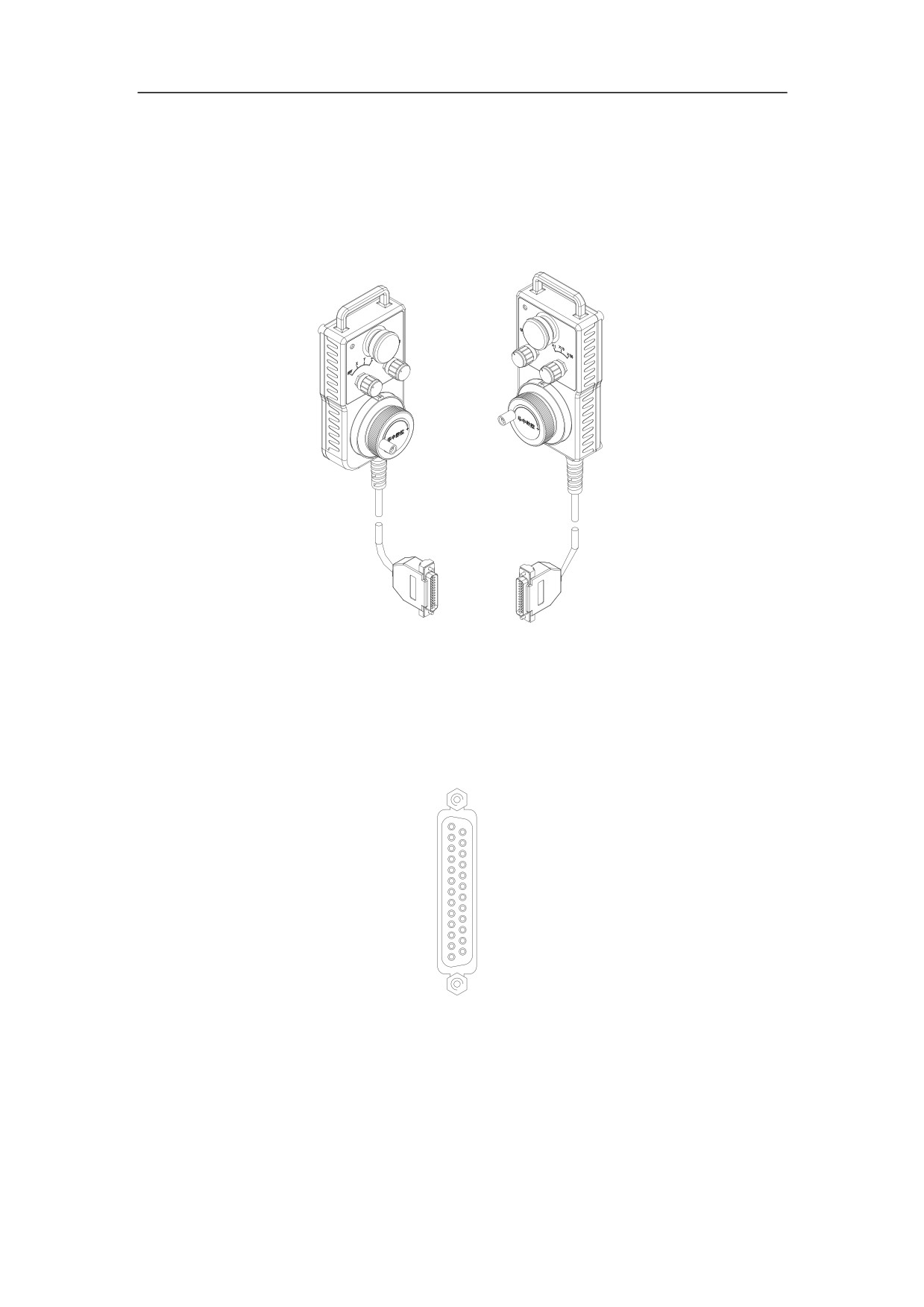
3.3 Connection to Handheld Unit
As it is shown in Figure 3-14, the handheld unit is equipped with the emergency stop
button, pilot lamps, axis switch (OFF, X, Y, Z), magnification switch (X1, X10, X100),
and the manual pulse generator. It is connected to XS8 of HNC-180.
DB25 PIN
Figure 3-14 Interface of Handheld unit
3.3.1 Handheld Interface on HNC-180
Handheld unit is connected to HNC-180 by XS8 (DB25 pin).
XS8(DB25 PIN)
1: 24VG
14:24VG
2: 24VG
15:24VG
3: +24V
1
14
16:+24V
4: X3.7
17:24VG
5: X2.7
18:X2.6
6: X3.6
19:X3.5
7: X3.4
20:X3.3
8: X3.2
21:X3.1
9: X3.0
22:Y2.4
10: Y2.5
23:Y2.6
11:Y2.7
24:HA
12:HB
13
25
25:+5V
13:5VG
Figure 3-15 Interface of XS8
25
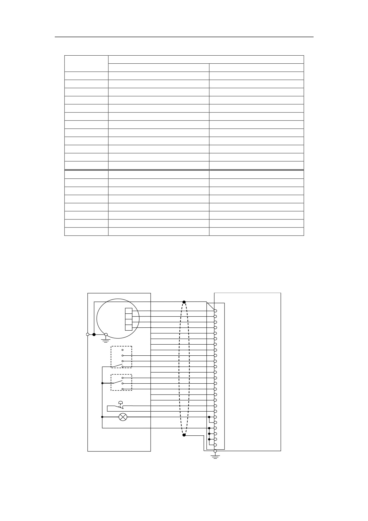
Table 3-9 Interface description of XS7
Description
Signal
Turning
Milling
+24V, 24VG
PLC power DC24V
PLC power DC24V
X2.6
2nd cycle start
2nd cycle start
X2.7
2nd feed hold
2nd feed hold
X3.0
Axis X selected
Axis X selected
X3.1
Undefined
Axis Y selected
X3.2
Axis Z selected
Axis Z selected
X3.3
Undefined
Undefined
X3.4
Ratio x1 on handheld unit
Ratio x1 on handheld unit
X3.5
Ratio x10 on handheld unit
Ratio x10 on handheld unit
X3.6
Ratio x100 on handheld unit
Ratio x100 on handheld unit
X3.7
2nd E-stop
2nd E-stop
Null
/
/
Y2.4
U4
U4
Y2.5
U5
U5
Y2.6
2nd cycle start pilot
2nd cycle start pilot
Y2.7
2nd feed hold pilot
2nd feed hold pilot
Null
/
/
HA
Phase A on handheld unit
Phase A on handheld unit
HB
Phase B on handheld unit
Phase B on handheld unit
+5V, 5VG
Handheld power DC5V
Handheld power DC5V
3.3.2 Connection to Standard Handheld Unit
The interface of standard handheld unit provided by our company is DB25 pin, which
can be directly connected to XS8 on HNC-180 device.
XS8
+5VG
+5VG
13
GN
+5V
+5V
25
+5V
MPG
HB
HB
12
B
HA
HA
24
A
Y2.4
11
Y2.5
23
Y2.6
10
OFF
Y2.7
22
X
Axis X
X3.0
9
Axis
Y
Axis Y
X3.1
21
HNC-180
Z
Axis Z
X3.2
8
X3.3
20
NC device
Ratio
x1
x1
X3.4
7
x10
x10
X3.5
19
x100
x100
X3.6
6
X2.6
18
X2.7
5
E-stop
24VG
24VG
17
X3.7
X3.7
4
+24V
16
3
pilot
24VG
24VG
15
2
Handheld
14
unit
1
PE
Figure 3-16 Connection to Standard Handheld Unit
26
3.3.3 Connection to Custom Handheld Unit
Please refer to standard handheld unit while designing I/O such as coordinate
selection, ratio selection, and pilot lamps etc. Moreover, the handheld unit can also be
in the form of external operation box or auxiliary control panel.
The type of I/O shall be NPN with DC24V. Please refer to section 3.4
The specification of MPG
(Manual Pulse Generator) is DC5V, TTL level,
phase-A output, and phase-B output.
27
3.4 I/O on NC device
3.4.1 I/O Interface
There is 32/24 NPN I/O interface on HNC-180.
3.4.1.1Characteristic of input interface
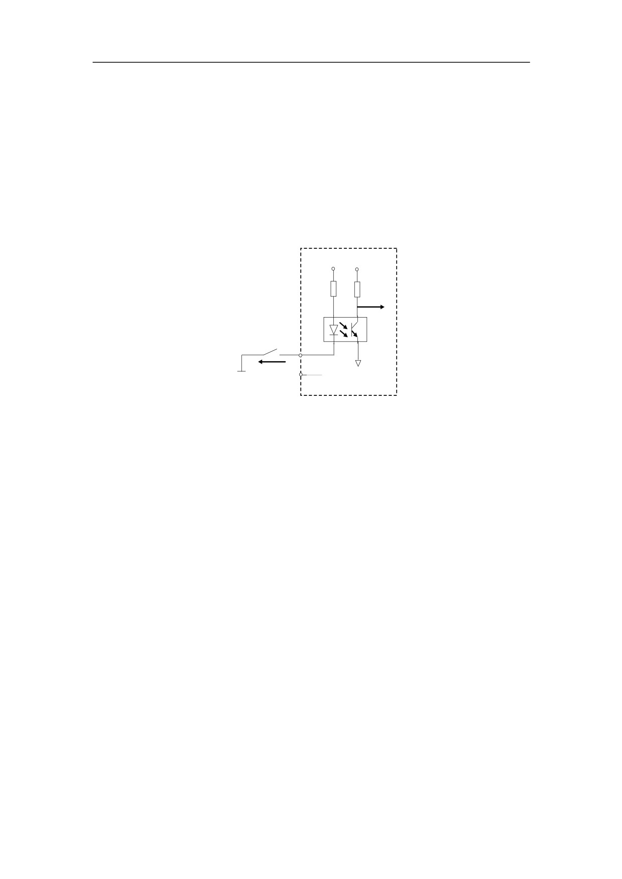
(1) Equivalent circuit
24V
+5V
IF=5~9mA
24VG
24VG
24VG - common ground of NPN input
Figure 3-17 Equivalent circuit of Input interface
(2)
Technical parameters
-
The optically coupled technique is adopted. The highest isolated voltage is
2500VRMS (one minute).
-
The supply voltage is 24V.
-
Turn-on current IF=5~9mA.
-
Maximum leakage current≤0.1mA
-
Filtering time is approximately 2msec.
Note: Any active I/O components (such as non-contact switch, Hall switch etc.)
must be NPN type with DC24V.
(3)
Typical application circuit
-
Connecting to external passive switches or relay contacts;
As it is shown in Figure 3-17, one contact of interface is connected with input,
the other contact of interface is connected with 24VG.
-
Connecting to external active switches
The type of NPN output with DC24V shall be selected as the active switch.
Please refer to the description of components, if necessary. The following
figure is the connection of active input switch.
28
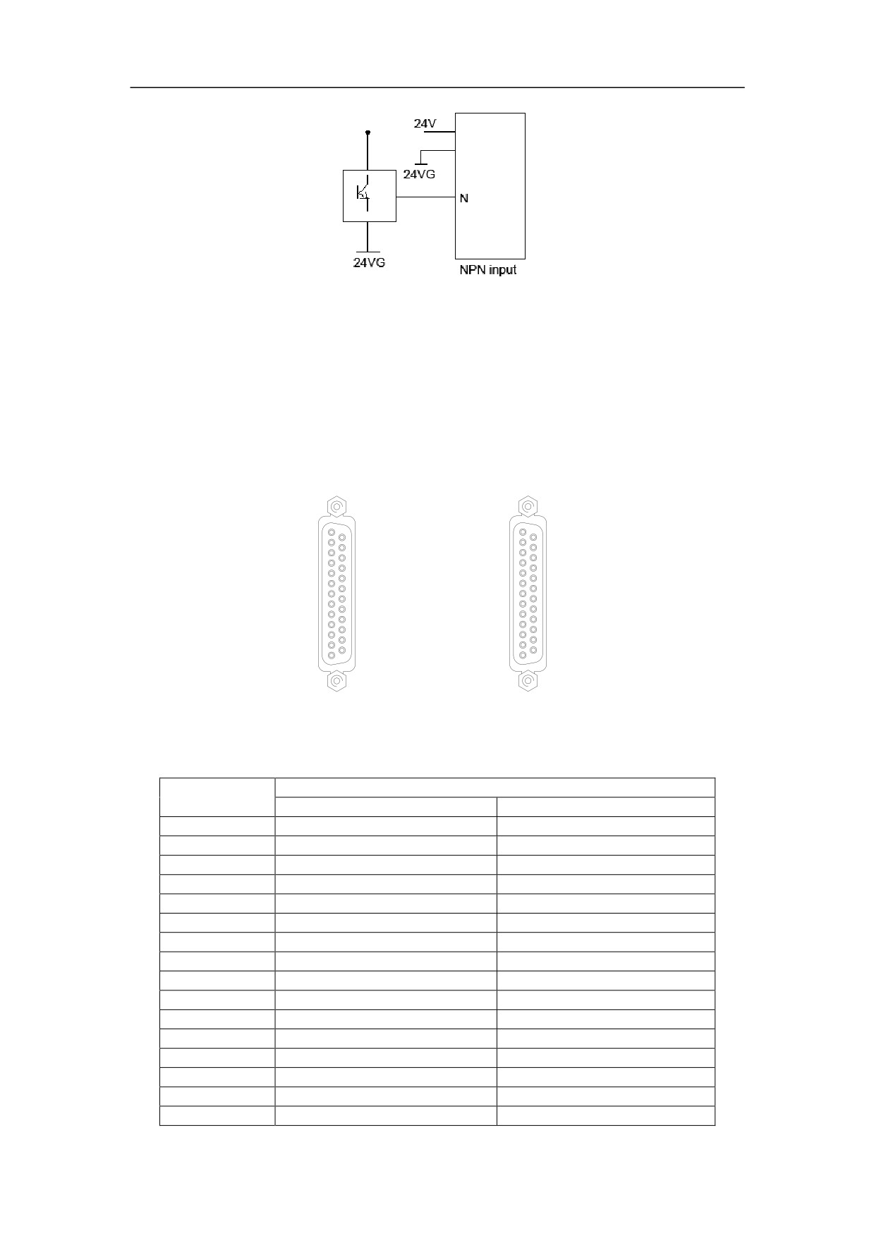
Figure 3-18 Connection of active input switch
3.4.1.2Pin of I/O input interface
PLC input interfaces are on XS7 (PLC input interface) and XS8 (handheld interface)
of HNC-180. Some PLC input interfaces can also be connected with XS5 (spindle
interface) or XS1~XS3 (feed axis interface) in parallel.
XS7(DB25 PIN)
XS8( D B 2 5 P
1: 24VG
1: 2 4 V G
14:24VG
14:24V
2: 24VG
2: 2 4 V G
15:X2.5
15:24V
3: X2.4
1
14
3: + 2 4 V
1
14
16:X2.3
16:+24
4: X2.2
4: X 3 . 7
17:X2.1
17:24V
5: X2.0
5: X 2 . 7
18:X1.7
18:X2.
6: X1.6
6: X 3 . 6
19:X1.5
19:X3.
7: X1.4
7: X 3 . 4
20:X1.3
20:X3.
8: X1.2
8: X 3 . 2
21:X1.1
21:X3.
9: X1.0
9: X3 . 0
22:X0.7
22:Y2.
10:X0.6
10: Y 2 .
23:X0.5
23:Y2.
11:X0.4
11:Y2
24:X0.3
24:HA
12:X0.2
12:HB
13
25
25:X0.1
13
25
25:+5V
13:X0.0
13: 5 G
Figure 3-19 Interface of XS7 and XS8
Table 3-10 Inputs of XS7 and XS8
Description
Signal
Turning
Milling
+24V, 24VG
PLC power DC24V
PLC power DC24V
X0.0
Axis X Ready
Axis X Ready
X0.1
Tailstock forward Ready
Axis Y Ready
X0.2
Axis Z Ready
Axis Z Ready
X0.3
REF point on axis X
REF point on axis X
X0.4
Tailstock backward Ready
REF point on axis Y
X0.5
REF point on axis Z
REF point on axis Z
X0.6
Turret Locked
Tool Locked
X0.7
Chuck Locked
Tool Released
X1.0
Tool 1
Spindle orientation is done.
X1.1
Tool 2
Spindle speed is reached.
X1.2
Tool 3
Zero spindle speed
X1.3
Tool 4
Undefined
X1.4
Tool 5/Spindle gear 4
Spindle gear 4
X1.5
Tool 6/Spindle gear 3
Spindle gear 3
X1.6
Tool 7/Spindle gear 2
Spindle gear 2
29
X1.7
Tool 8/Spindle gear 1
Spindle gear 1
X2.0
Overtravel input
Overtravel input
X2.1
E-stop input
E-stop input
X2.2
External alarm
External alarm
X2.3
Spindle alarm
Spindle alarm
X2.4
Foot pedal switch
Undefined
X2.5
Operational door switch
Undefined
X2.6
2nd cycle start
2nd cycle start
X2.7
2nd feed hold
2nd feed hold
X3.0
Axis X selected
Axis X selected
X3.1
Undefined
Axis Y selected
X3.2
Axis Z selected
Axis Z selected
X3.3
Undefined
Undefined
X3.4
Ratio x1 on handheld unit
Ratio X1 on handheld unit
X3.5
Ratio x10 on handheld unit
Ratio X10 on handheld unit
X3.6
Ratio x100 on handheld unit
Ratio X100 on handheld unit
X3.7
2nd E-stop
2nd E-stop
Null
/
/
Note: X0.0 (Axis X Ready), X0.1 (Axis Y Ready), X0.2 (Axis Z Ready), X1.0 (Spindle
orientation is done), X1.1 (Spindle speed reached), X1.2 (Zero spindle speed), and
X2.3 (Spindle alarm) are parallel connection with the signals of feed axis interface and
spindle interface. The operator can use one of them.
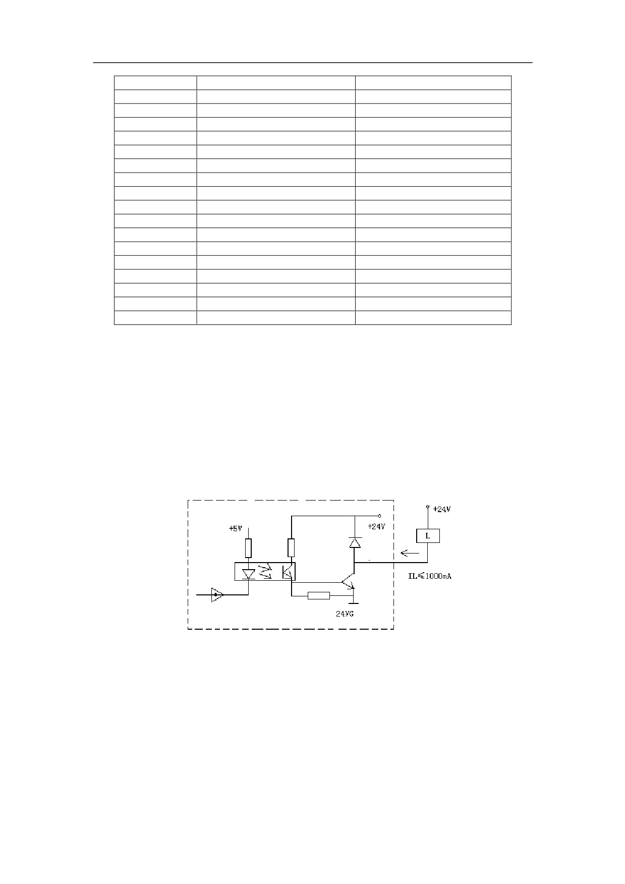
3.4.1.3Characteristic of output interface
(1) Equivalent circuit
Figure 3-20 Equivalent circuit of output interface
(2) Technical parameters
-
The optically coupled technique is adopted. The highest isolated voltage is
2500VRMS (one minute).
-
The supply voltage is 24V.
-
The maximum output current is 100mA.
30
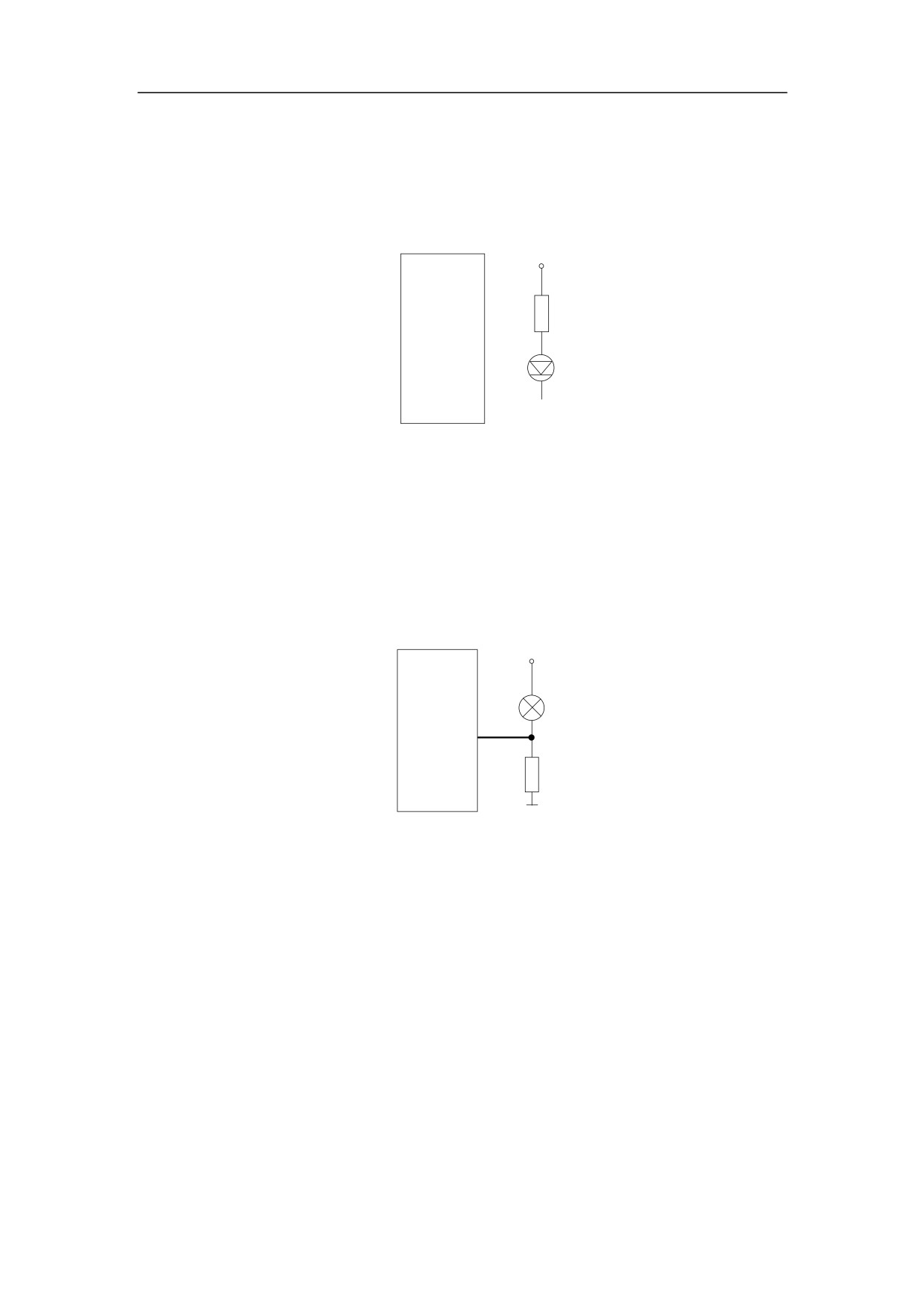
(3) Typical application circuit
-
To drive a LED
A resistance about 10mA is required in series to control the current flowing
through LED.
+24V
HNC-180
2.5K
Il=10mA
N
NPN output
Figure 3-21 Output to drive LED
-
To drive a filament pilot lamp
A preheating resistance is required to reduce the current shock while turning
the pilot on. The ohm value of the resistor should be large enough to keep the
pilot dark when it is off.
+24V
HNC-180
N
preheating
resistance
24VG
NPN output
Figure 3-22 Output to drive a filament pilot lamp
-
To drive an inductive load (such as relay)
A flywheel diode shall be connected in parallel with the coil of the relay to
protect the output circuit from interference (some relays have been equipped
with flywheel diodes).
Note: The voltage of coil shall be DC24V.
31
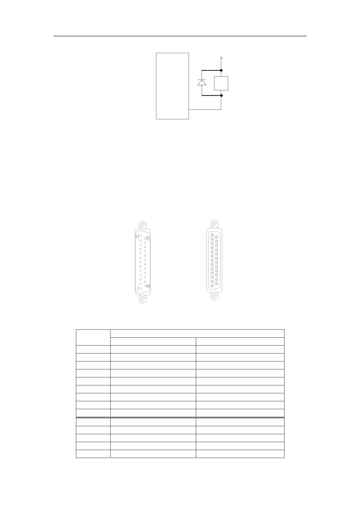
+24V
HNC-180
KA
flywheel diode
N
NPN output
Figure 3-23 Output to drive an inductive load
3.4.1.4Pin of I/O output interface
PLC output interfaces are on XS9 (PLC output interface) and XS8 (handheld interface)
of HNC-180. Some PLC output interfaces can also be connected with XS5 (spindle
interface) or XS1~XS3 (feed axis interface) in parallel.
XS9(DB25 PIN)
XS8( D B 2 5 P
13:Y0.0
1: 2 4 V G
25:Y0.1
14:24V
12:Y0.2
2: 2 4 V G
24:Y0.3
15:24V
11:Y0.4
3: + 2 4 V
1
14
23:Y0.5
16:+24
10:Y0.6
4: X 3 . 7
22:Y0.7
17:24V
9
:Y1.0
5: X 2 . 7
21:Y1.1
18:X2.
8
:Y1.2
6: X 3 . 6
20:Y1.3
19:X3.
7
:Y1.4
7: X 3 . 4
19:Y1.5
20:X3.
6
:Y1.6
8: X 3 . 2
18:Y1.7
21:X3.
5
:Y2.0
9: X3 . 0
17:Y2.1
22:Y2.
4
:Y2.2
10: Y 2 .
16:Y2.3
23:Y2.
3
:Null
11:Y2
15:Null
24:HA
2
:24VG
12:HB
14:24VG
13
25
25:+5V
1
:24VG
13: 5 G
Figure 3-24 Interface of XS9 and XS8
Table 3-11 Outputs of XS9 and XS8
Description
Signal
Turning
Milling
24VG
PLC power DC24V
PLC power DC24V
Y0.0
Reset (clear the alarm)
Reset (clear the alarm)
Y0.1
Enabled
Enabled
Y0.2
Spindle CW rotation
Spindle CW rotation
Y0.3
Spindle CCW rotation
Spindle CCW rotation
Y0.4
Spindle brake
Spindle brake
Y0.5
U6
Spindle orientation
Y0.6
Chuck Locked
Tool Locked
Y0.7
Chuck Released
Tool Released
Y1.0
Turret CW
U7
Y1.1
Turret CCW
U8
Y1.2
Coolant
Coolant
Y1.3
Lubrication
Lubrication
Y1.4
Spindle gear 4
Spindle gear 4
32

Y1.5
Spindle gear 3
Spindle gear 3
Y1.6
Spindle gear 2
Spindle gear 2
Y1.7
Spindle gear 1
Spindle gear 1
Y2.0
U0/Tailstock forward
U0
Y2.1
U1/Tailstock backward
U1
Y2.2
Spindle Reset
Spindle Reset
Y2.3
Spindle Enabled
Spindle Enabled
Y2.4
U4
U4
Y2.5
U5
U5
Y2.6
2nd cycle start pilot
2nd cycle start pilot
Y2.7
2nd feed hold pilot
2nd feed hold pilot
null
/
/
Note: Y0.0 (Reset), Y0.1 (Enabled), Y0.2 (Spindle CW rotation), Y0.3 (Spindle CCW
rotation), Y0.4 (Spindle brake), and Y0.5 (U6) are parallel connection with the signals
of feed axis interface and spindle interface. The operator can use one of them.
3.4.2 Description of PLC Address
In the system program and PLC program, the on-off inputs from machine tool are
defined as X. The on-off outputs to machine tool are defined as Y.
There are 8 bits (one byte) in each group of on-off inputs or outputs. For example,
X0.0~X0.7 of XS6 on HNC-180 is in X[00]. (X0.0 takes the first bit of X[00], and X0.1
takes the second bit of X[00]…).
There are three kinds of PLC input/output:
1. I/O on PLC interface
For HNC-180, there are 32 bits of inputs, and 24 bits of outputs. Every 8 bits is
composed of a byte. The inputs are in X[00]~X[03], and the outputs are in
Y[00]~Y[02].
2. Digital outputs relevant to spindle analogue voltage
They are in Y[28] and Y[29].
Note: The process of outputting the signal analog voltage command: PLC
program calculates the digital outputs. Then, it is converted to analog voltage by
internal D/A module.
PLC program manages the digital outputs, which takes 16bits(two bytes) i.e. two
groups of output signal.
Thus, the spindle analog voltage is regarded as the output signal to handle.
3. The inputs to keys and the outputs to pilots on MCP (machine control panel).
There are three rows of buttons on MCP and two ratio switches:
-
The first row (9 buttons): the inputs are in X[30] and 0 bits of X[31].
33
-
The second row (10 buttons): the inputs are in 1~7th bit of X[33] and 0~2nd bit
of X[32].
-
The third row (9 buttons): the inputs are in 3~7th bit of X[32] and 0~3rd bit of
Y[33].
-
The two ratio switches contains 8 gears and 3 gears, respectively. The
inputs are X[34] and X[35].
34
3.5 Design of E-Stop and Overtravel Released
There is an E-stop (emergency stop) input pin on both XS7 (PLC input interface) and
XS8 (handheld unit). At least one E-stop button shall be connected in the following
case.
-
if there is an emergency, it is used to stop NC machine immediately or turn off the
main supply of power devices (such as servo drivers).
-
if there is an alarm message, E-stop button shall be pressed. Do not release
E-stop button until the alarm message has been fixed.
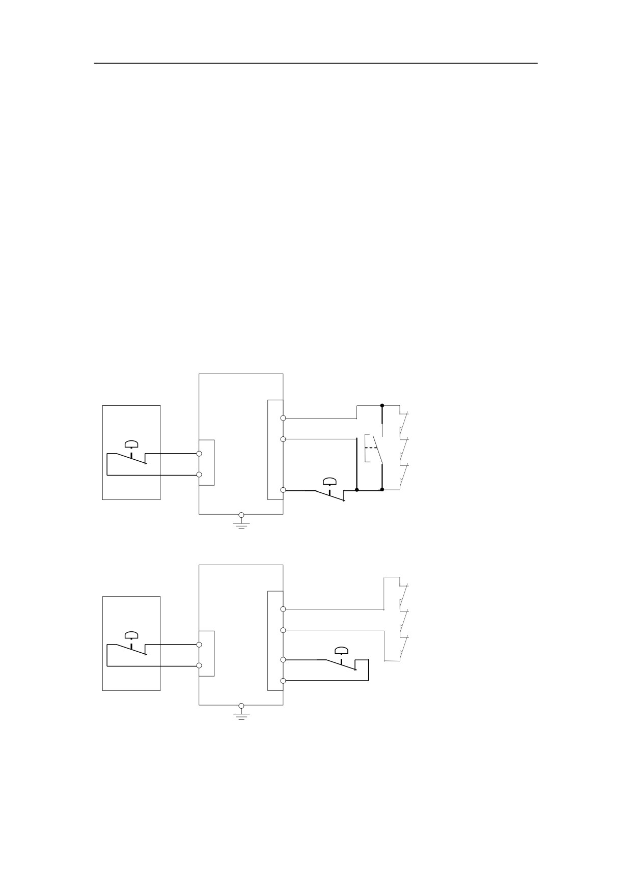
There is no overtravel released button on the control panel of HNC-180. An external
overtravel released button can be used to release the overtravel, if the overtravel limit
switch is pressed (Figure 3-25). If the overtravel released button is not used, the
overtravel is released after the resetting (Figure 3-26).
HNC-180
Handheld unit
XS7
14
24VG
Axis-1 Overtravel limit switch
Overtravel release
button
2nd ESTOP
XS8
5
X2.0
Axis-2 Overtravel limit switch
X3.7
4
Axis-3 Overtravel limit switch
24V
17
ESTOP
4
X2.1
Figure 3-25 Recommended design of E-stop and Overtravel (with overtravel released button)
HNC-180
Axis-1 Overtravel limit switch
Handheld unit
XS7
5
X2.0
Axis-2 Overtravel limit switch
2nd
E-stop button
XS8
14
24VG
Axis-3 Overtravel limit switch
X3.7
4
E-stop button
4
X2.1
24V
17
1
24VG
Figure 3-26 Recommended design of E-Stop and Overtravel (no overtravel released button)
35

The following table shows the input interface of E-stop.
Table 3-12 Input Interface of E-stop
Signal
Interface
Signal
Interface
Pin
Type
Description
Description
X2.1
E-stop input
XS7
17
PLC input
DB25 (male plug, female socket)
X3.7
2nd E-stop input
XS8
4
Handheld unit
DB25 (male plug, female socket)
More than one E-stop button can be used if necessary. The normally closed contacts
of each emergency stop button are connected to input interface of NC device in series.
Generally, E-stop buttons are released and its contacts are closed. While E-stop
button is pressed, the contacts are open and E-Stop signal is sent to NC device. Then,
the devices (such as feed motor, spindle motor, tool magazine/turret motor etc.) are
stopped.
The normally closed contacts of the positive/negative overtravel limit switches are
connected to the overtravel loop of NC device in series. Generally, the overtravel limit
switch is open. If the overtravel limit switch is pressed, the contacts are closed. Then,
the overtravel loop of NC device is closed, and the alarm message is shown.
Same as E-stop alarm, NC device are stopped and the system shows the alarm
message if there is an overtravel. To release the overtravel, the following steps can be
done:
1) If there is no overtravel released button, press RESET key to reset the system.
2) If there is an overtravel released button, press this button. Then, press RESET
key. Note: Do not release this button until NC device is released.
3) Press the axis key with the correct direction to release the overtravel limit
switch.
4) Release the overtravel release button
36
4 Debugging
This chapter would introduce the steps for the first start-up:
-
Preview of Operation
-
Trial Operation
-
PLC Debugging
-
Machine Debugging
37
4.1 Checking before Operation
4.1.1 Inspection of Wiring
Make sure that all cables are connected correctly, especially:
-
The polarity of damper diodes for relays and solenoid valves (please refer to
Chapter 1).
-
The phase sequence of strong current cables on motor.
-
Position control cable and position feedback cable of feeding device and strong
current cable on motor shall be connected to the corresponding interface as
shown in Figure 5-1.
HNC-180
HSV-16 servo driver
Servo motor
XS1
Command
Feedback
Feedback
Power supply
Connect to the same
servo driver
Connect to the same servo driver
Figure 4-1 Connect to HSV-16, HSV-20D, Yaskawa or Matsushita servo with pulse interface
-
Ensure that the type of analog speed command received by spindle unit is voltage,
and check the wires to avoid damages to the related interfaces. The analog output
of XS5 on NC device is -10V~+10V.
-
Make sure that all grounding wires are reliable and correctly connected.
-
Make sure that the emergency stop button and emergency stop circuit are
effective. Pressing the emergency stop button down or cutting off the emergency
stop circuit can cut out the power source of moving units such as feed driver,
spindle drive unit etc. Please refer to Chapter 3.5 for the design of emergency
stop circuit.
4.1.2 Power Inspection
-
Make sure that the voltage and the polarity of each part of the circuit are correct,
especially, the polarity of DC24V, and the circuit of power supply shall not be short
circuit.
-
Make sure that the specification of each part of the power supply in the circuit is
correct.
-
Make sure that the specification of each transformer in the circuit is correct, and
the directions of I/O wires are connected in correct direction.
38
4.1.3 Device Inspection
-
Make sure that each motor (spindle motor, feed motor) in the system is separated
from mechanical transmission part, and reliably set down and fixed.
-
Make sure that each power supply switch, especially the power supply switch of
servo drive is off.
39
4.2 Trial Operation
4.2.1 Power On
Press E-stop button before the NC device is turned on or off.
Ensure the power of servo drive is off to prevent from the wrong action
or malfunction due to the wrong setting of parameters, before doing the
following steps:
1) Press E-stop button to ensure all the air switches in the system are
open;
2) Turn the air switch of main power supply in the cabinet is on.
3) Turn the air switch or fuse with AC220V on, and ensure that the
voltage of NC device is DC24V, and the power is DC5V.
4) Check the power supply of other parts.
4.2.2 Setting Parameters
After HNC-180 device is turned on, please check the system parameters
according to the hardware. For detailed information, please refer to Chapter 4.
Note: Please set the servo parameters and internal parameters of servo
according to servo manual, before the servo is powered on.
Do read the PLC programming manual and set PLC parameters
according to the hardware configuration.
Attention: In PLC programming, the parameter shall not be set as 0, if
one [P] parameter is taken as denominator(such as spindle speed
transmission ratio denominator). Otherwise, the system would crash.
4.2.3 Inspection of External Status
Do the following inspections before the servo power is on:
-
Check each feed drive unit and spindle drive unit, after the power is on.
-
Check the required status reply signal, such as feed drive, spindle drive etc.
4.2.3.1PLC I/O Status
The operator can check the status of I/O signal (X, Y) by inspecting PLC status.
40
Moreover, the user can debug PLC program by inspecting the status of intermediate
relay (R relay, not refer to actual relay in control cabinet), which is used for PLC
programming.
To monitor PLC status, the operator can press DGN function key on MCP of NC
device. For detailed information, please refer to the operation manual of HNC-180.
The value of X and Y is shown in binary. A group is composed of 8 bits, and each bit
represents one bit of external on-off input or output signal. For example, X[00]
includes 8 bits, which represents the inputs of X0.1~X0.7 from right to left, respectively,
and X[01] represents the inputs of X1.0~X1.7 etc. Similarly, Y[00] represents the
outputs of Y0.0~Y0.7, and Y[01] represents the outputs of Y1.0~Y1.7.
If the status of the connected input component varies (such as over-travel switch
being pressed), the corresponding display of on-off numerical status would vary, from
which the connection of the on-off I/O circuit can be checked.
4.2.3.2PLC I/O Address
PLC I/O addresses of HNC-180 device are defined as follows:
External on-off input signal: X[00]~X[03];
Input signal from button on panel: X[30]~X[45];
External on-off output signal: Y[00]~Y[02];
External on-off output signal: Y[28]~Y[29]; spindle speed control D/A;
Output signal from pilot on panel: Y[30]~Y[37].
4.2.4 Servo Power On
4.2.4.1Checking before Servo Power On
If any parameter has been modified, the operator shall turn the power supply of
NC device off for 3 minutes, and turn it on again. Then, do the following steps:
-
If the spindle encoder is used, the operator can rotate the axis of encoder to
monitor the spindle speed and the spindle rotation, which can check the setting of
spindle encoder.
-
When the servo unit is connected to the control power supply, the position
feedback control circuit is in the working mode. The operator can see the actual
coordinate value including MCS (machine coordinate system), WCS (workpiece
41

coordinate system), and RCS (relative coordinate system) to check the actual
position feedback of motor by press
POS→
ALL soft keys on NC device. For
example, when the operator rotates the motor spindle (without brake) manually,
the actual coordinate value on NC device would change. Then, the setting of axis
parameters and the connection between servo and NC device can be checked.
Do not turn the servo on after manually rotating the motor.
4.2.4.2Turn Servo Power On
-
Ensure the PLC control logic for the servo including power on, enabled, and
disabled function and the circuit are correct.
-
Turn on the circuit breaker of servo power supply.
-
Ensure that the brake of motor is released. To check the brake, the operator can
measure the power supply of brake control (DC24V), or hear the clatter when the
brake is released at the instant of turning on the power supply.
-
If handheld encoder is associated with the servo drive, this handheld unit can be
used to directly control the motor operation and verify the correct connection of
servo unit to the motor.
-
Check the function of reference point return for each axis, once all feed axes are
debugged.
For Stepper Motor Driver
-
Ensure the type of pulse signal received by the stepper driver is the same as the
setting of the pulse type in HNC-180.
-
Ensure the correct number of beats of step motor is correct. Otherwise, the
reference point would not be returned.
-
Rotate the motor slowly and then quickly in jog or handheld mode. If there is
abnormal sound or blocking during the motor rotation, please properly increase
the value of jerk time for rapid traverse, jerk for rapid traverse, jerk time for
machining, and jerk for machining.
For Servo Driver with Pulse Interface
-
Ensure the type of pulse signal received by the servo driver is the same as the
setting of the pulse type in HNC-180.
-
Ensure the correctness of the motor revolution. It is usually feedback pulse from
motor or servo * 4.
42
-
Ensure the consistency of the variation of the feedback value during motor
rotation with NC device command value. The operator can control the motor to
move a short distance. Then, according to the variation of command value and
feedback value, correct the sign of E-gear(NC) and E-gear(Servo), until the
variation of the feedback value is same as that of the command value.
-
Control the motor to move a short distance (such as 0.1mm), and check if the
feedback value is same as the command value of the coordinate axis. If they are
not same, the operator shall adjust the command multiple frequency of servo unit
(usually there are two parameters: numerator and denominator of command
multiple frequency) until the command value and the feedback values displayed
on the screen of NC device are identical.
Example: Given that NC device command value is 0.1mm, the feedback value is
0.05mm, and E-gear(NC):E-gear(Servo)=1:1. Then, the operator can adjust the
parameters in three ways to get the same variation between the feedback value
and the command value of NC device:
1) Set the command multiple frequency of servo unit as 2.
2) Set as twice as the feedback pulses of servo unit.
3) Set the E-gear(NC) as 2.
Thereafter, to fit with the variation of lead screw pitch and transmission ratio in the
machine connection, only two parameters i.e. pulse1 and pulse2 in axis
parameter is required to adjust. For more detailed information, please refer to
chapter 4.
43
4.3 PLC Debugging
PLC function is offered in HNC-180. In aid of standard PLC applications with settings
of related PMC user parameters, most NC turning machines and NC milling machines
can be controlled. For the detailed information, please refer to HNC-180 PLC
programming manual.
4.3.1 Main Elements of PLC Debugging
-
Operate NC device to monitor on-off I/O status, and check PLC I/O points one by
one for correct connection and logic relation against machine tool circuit diagram.
-
Check the machine tool over-travel limit switch for correct operation.
4.3.2 Process of PLC Debugging
-
Check each button on the operation panel, the on-off input signals, the system
response and external logic circuit for correct operation. For instance, if the
coolant button is pressed, then, the button lamp is on and AC contactor of coolant
motor starts to work. If it is pressed once again, the lamp is turned off and AC
contactor of coolant motor stops working.
-
Return the reference point on each axis. Manually put the reference point
response signal, and examine whether every coordinate axis can implement the
reference point return with the correct operation or not.
-
Connect the limit switch and the reference point return signal for every coordinate
axis correctly, manually control the limit switch and reference point switch, and
repeat the above two debugging steps to examine the effect of these switches.
-
Check the correctness of the system alarm messages, the external alarm
messages defined in PLC program, and the corresponding system action, when
the on-off input alarm signal is inputted. For example, when the spindle alarm
signal is valid, the spindle and the machining program would stop.
4.3.3 Methods for PLC Debugging
When PLC program cannot be executed in the expected procedure, the operator can
follow the following steps to debug PLC:
-
Check PLC input status (register X), if not, check the external circuit. For the
command M, S, T, the operator can write a program including these commands,
and then execute this program in AUTO (automatic) or SBL (single block) mode
(PLC status cannot be monitor in MDI mode during the running) to monitor the
44
related registers during execution.
-
Check PLC output status (register Y). If not, check the input condition or the
corresponding setting of PLC user parameters.
-
Check if the electronic switch or the relay directly controlled by the on-off output
(register Y) can work. If not, check the connecting wire.
-
Check if the contactor controlled by the relay or other switches (solenoid valve)
can work. If not, check the connecting wire.
-
Check the performance unit, including motor, hydraulic circuit, pneumatic circuit
etc.
45
4.4 Machine Debugging
4.4.1 Emergency Stop and Limit
There are software limit in system. For the safety, it is suggested to use the hardware
limit. The route limit switch is installed at the positive and negative direction of axes.
The parameters related to emergency stop and limit:
-
PLC parameter 007078
no detection of MCP emergency stop signal: check if the emergency stop is
controlled by MCP emergency stop signal.
-
PLC parameter 007079
no detection of handheld emergency stop signal: check if the emergency stop is
controlled by handheld emergency stop signal.
-
PLC parameter 007075
individual limit signal: check if there are individual limit switch to control hardware
over-travel on each axis.
-
PLC parameter 007081
no detection of limit alarm signal: check if there are detection of limit alarm
If the limit switch is installed, please do ensure the over-travel limit switch is
valid before machine debugging.
-
Check the on-off I/O status of NC device, and press the over-travel limit switch on
the machine to observe the change of the corresponding on-off input status, and
check the correct connection of the over-travel limit switch.
-
Move the axis slowly in jog or handheld mode to verify the validity of over-travel
limit switch, the correctness of alarm message display, and the validity of
over-travel released button (please refer to Chapter 3.5 for the operation of the
over-travel released button).
4.4.2 Axis setting
The parameters related to axis are 100003~100036 and 200003~200036.
-
Check the consistency of the direction and distance of machine with the
corresponding commands from NC device. If not, the operator can modify the
value and sign of Pulse1 and Pulse2 of axis parameters.
-
Pulse1 and Pulse2 can be set according to the lead-screw and the transmission
ratio to keep the consistency of the command value with the actual value of
46
machine. There are two ways (calculation, measurement) to set :
1) Calculation
Given that HSV-16 is used, the transmission ratio is 2:5, the lead-screw is
6mm, and the revolution of motor encoder is 2500pulses. There are four
subdivisions for servo driver and NC device, respectively. The motor
revolution is
2500*4*4=40000p/r. The distance of tool movement is
6*1000*2/5=2400μm. Thus, Pulse1:Pulse2=2400:40000=3:50.
2) Measurement
pulse
1(
m)
movingdistance
for each revolution
(m)
pulse2
pulsesfor each revolution
Please do the measurement more than once and try to increase the
distance of measurement, because there is measurement error.
-
According to the condition of mechanical transmission and the requirement of
design, please set the rapid traverse speed, the maximum feedrate, the rapid
traverse speed at REF, and the positioning speed at REF for each axis, correctly.
Note:
1) The rapid traverse speed is the maximum among these parameters.
2) The setting of speed should not lead to the over-rated revolution of servo
motor.
3) The rapid traverse speed at REF shall be higher than the positioning
speed at REF.
Set the characteristics of jerk for each axis according to the running status and
mechanical transmission:
-
The more the jerk time and jerk is, the acceleration/deceleration is slower, the less
impact of machine motion is, the machining efficiency is lower. The less the jerk
time and jerk is, the quicker the acceleration/deceleration is, the more impact of
machine motion is, and the higher the machining efficiency is.
-
The principle of setting acceleration and deceleration is that reducing the
acceleration and deceleration time and jerk time on the premise of no alarm of
drive unit, no stepper of motor and no obvious shock of machine motion to
increase the response of coordinates and machining efficiency. If the acceleration
and deceleration time or jerk time are set too small, it would lead to alarm of drive
unit, out of step of motor, or machine vibration. the current of servo should not be
too heavy during the start-up and the shut-down of the acceleration and
deceleration. The recommended current is not more than 60% rated current of
servo.
47
4.4.3 Reference point return setting
Mechanical reference point return switch can be installed, floating zero can also be
set in the software. The mechanical reference point can be set in these two ways. The
related parameters are as followed:
-
PLC parameter 007017
REF switch on machine: mechanical REF return mode or floating zero of REF
return mode
-
PLC parameter 007000
Alarm when axis returns to REF point once powered: determine whether there is
an alarm message about REF point return.
-
PLC parameter 007084
Detection of floating zero lost: check if the floating zero is lost.
-
Axis parameter 100008~100012 and 200008~200012
the direction, speed, and offset of mechanical REF return, etc
Note: Do check the validity of over-travel limit switch before the operation of
reference point return.
-
Check the validity of over-travel switch for the reference point return.
Generally, the mechanical reference point is installed at the maximum travel. The
valid travel of REF return block is more than 25mm to guarantee the enough
deceleration distance and return the reference point precisely. The quicker the
mechanical REF return is, the longer the REF switch is. Otherwise, there would be
no enough deceleration distance to affect the accuracy of REF return, causing by
the carriage moved by CNC acceleration and deceleration and machine inertia
and passing REF block.
1) Manually press the reference point switch during the movement of machine
tool to check the validity of the reference point return process.
2) Operate the machine tool and press the reference point switch by the
reference point block to check the validity of the process of reference point
return. The recommended speed of reference point return is under
1000mm/min.
Note: The block of reference point shall be put within the certain distance.
The recommended length is above 30mm of the valid travel distance.
Otherwise, the block of reference point would be rushed over as the high
speed of reference point return.
48