Century Star HNC-180 series HNC-180xp/T3, HNC-180xp/M3, HNC-180GCE. Connection Manual (V2.0) - page 1
Century Star HNC-180 series
HNC-180xp/T3
HNC-180xp/M3
HNC-180GCE
Connection Manual
V2.0
2015/05
Table of Contents
Table of Contents
TABLE OF CONTENTS
I
1 PRECAUTION
3
1.1
TRANSPORTATION AND STORAGE
3
1.2
INSPECTION
4
1.3
INSTALLATION AND WIRING
5
1.4
OPERATION AND MAINTENANCE
6
2 INSTALLATION
7
2.1
CONNECTION
7
2.1.1
NC Device Type
7
2.1.2
Total Connection Diagram
8
2.2
DIMENSION
9
2.3
POWER SUPPLY CONNECTION
10
2.3.1
General Requirement
10
2.3.2
Grounding
11
2.4
INSTALLATION REQUIREMENTS FOR CABINET
12
2.5
DESIGN OF ELECTROMAGNETIC COMPATIBILITY
13
3 INTERFACES
14
3.1
CONNECTION TO DRIVE UNITS
14
3.1.1
Interface Description of XS1, XS2, XS3
14
3.1.2
Connection to Stepper Motor Drive Unit
15
3.1.3
Connection to Servo with Pulse Interface
16
3.2
CONNECTION TO SPINDLE DEVICE
19
3.2.1
Relevant Interfaces
19
3.2.2
Spindle Start and Spindle Stop
21
3.2.3
Spindle Speed Control
21
3.2.4
Spindle Orientation Control
21
3.2.5
Spindle Gear Control
21
3.2.6
Connection to Spindle Encoder
21
3.2.7
Connection Example―Three-phase Asynchronous Motor
22
3.2.8
Connection Example―Spindle Drive
22
3.2.9
Parameters related to Spindle device
24
3.3
CONNECTION TO HANDHELD UNIT
25
3.3.1
Handheld Interface on HNC-180
25
3.3.2
Connection to Standard Handheld Unit
26
3.3.3
Connection to Custom Handheld Unit
27
3.4
I/O ON NC DEVICE
28
3.4.1
I/O Interface
28
3.4.2
Description of PLC Address
33
3.5
DESIGN OF E-STOP AND OVERTRAVEL RELEASED
35
4 DEBUGGING
37
4.1
CHECKING BEFORE OPERATION
38
4.1.1
Inspection of Wiring
38
4.1.2
Power Inspection
38
4.1.3
Device Inspection
39
4.2
TRIAL OPERATION
40
4.2.1
Power On
40
4.2.2
Setting Parameters
40
i
Table of Contents
4.2.3
Inspection of External Status
40
4.2.4
Servo Power On
41
4.3
PLC DEBUGGING
44
4.3.1
Main Elements of PLC Debugging
44
4.3.2
Process of PLC Debugging
44
4.3.3
Methods for PLC Debugging
44
4.4
MACHINE DEBUGGING
46
4.4.1
Emergency Stop and Limit
46
4.4.2
Axis setting
46
4.4.3
Reference point return setting
48
4.4.4
Spindle Function
49
4.4.5
Machine Error Compensation
53
5 FAULT DIAGNOSIS
56
5.1
FAULT AND SOLUTION
56
5.1.1
Abnormal Start-up
56
5.1.2
E-Stop and Reset
56
5.1.3
Abnormal Running of Servo
57
5.1.4
Abnormal Frequency Converter and Servo Spindle
61
5.1.5
Abnormal Running of I/O
62
5.2
ALARM MESSAGES
63
5.2.1
Check Alarm Messages
63
5.2.2
List of Alarm Messages
64
6 EXAMPLE OF TYPICAL DESIGN
65
6.1
OVERVIEW
65
6.2
EXAMPLE OF DESIGN
66
6.2.1
Brief Introduction
66
6.2.2
Overall Diagram
67
6.2.3
I/O Specification
67
6.2.4
Circuit Diagram
67
ii

1 Precaution
1.1 Transportation and Storage
The product should be transported properly according to its weight.
The number of stacked products must not be more than what stipulated.
Do not climb up or stand on the product. Do not stack heavy things on it.
Dragging its cable to move or lift the product is not allowed.
Protect the front panel and screen from impact and cut.
Keep damp-proof while storing and transporting.
Let us know in time if the product has been stored overtime.
3
1.2 Inspection
Check if the product is what the operator ordered.
Check if there is damage of the product during the transportation.
Comparing to the list, check if all the components are complete.
Please contact us in time if the product type is wrong, lack of accessories or
damaged during the transportation.
4
1.3 Installation and Wiring
Workers undertaking wiring or inspection must be qualified to do the jobs.
The NC device must be grounded reliably. The earth-resistance must be less
than 4 ohm. Do not take the neutral as a ground. Otherwise, the system may
not work normally and stably because of interference.
Installation and wiring shall be correct and firm to avoid wrong operation.
Any voltage at terminals must have its correct value and polarities (+, -) as
mentioned in the manual. Otherwise, the short circuit or permanent damage to
the machine may occur.
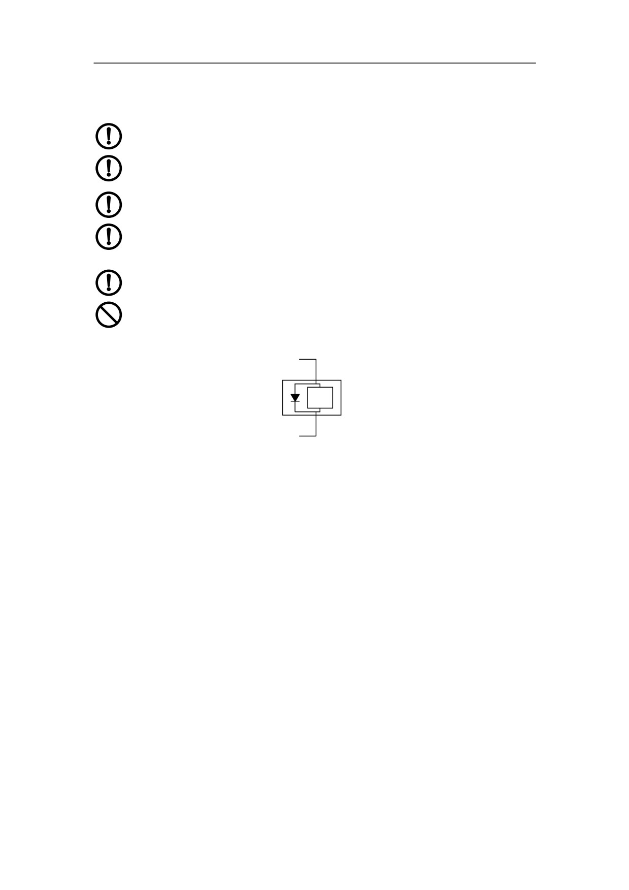
The surge-absorbed diode connected to NC device must be wired as shown in
Figure 1-1 to prevent the damage to device.
It is absolutely not allowed to insert or pull out any plug or open the NC cabinet
door with the power supply on.
PLC output
Relay coil
DC+24V
Figure 1-1 surge-absorbed diode
5

1.4 Operation and Maintenance
Personnel to operate and maintain the device must be competent for their work.
Before plugging in to get the main source, make sure that the main switch is off
to avoid accidental start-up.
Do not refit the device.
Do not turn on and off the system frequently. The interval between on and off
operations must be at least 3 minutes.
The operator’s hands must be kept dry, clean and no greasy dirt during
operation. It is suggested to keep the clear protection film on the panel.
Do not press the keys hard. It is not allowed to strike at the keyboard with
wrench or other sharp-edged and hard articles.
Operators shall not leave the machine while operating the devices.
Power supply shall be turned off before checking, replacing or installing parts or
elements.
When short-circuit or overload happens, do not turn on the power again unless
checking and fixing the breakdown.
When alarm has happened, do not restart the device unless the accident is
cleared off.
Do not install or operate the device if it is damaged or lack of parts and
elements.
6

2 Installation
2.1 Connection
2.1.1 NC Device Type
Specification of NC device:
HNC - 180xp/T3
Century Start
Application Type
M: Milling
180xp
T: Turning
HNC - 180GCE
Century Start
Application Type
G: Grinding
180xp
C: Circular
E: Economic
7
2.1.2 Total Connection Diagram
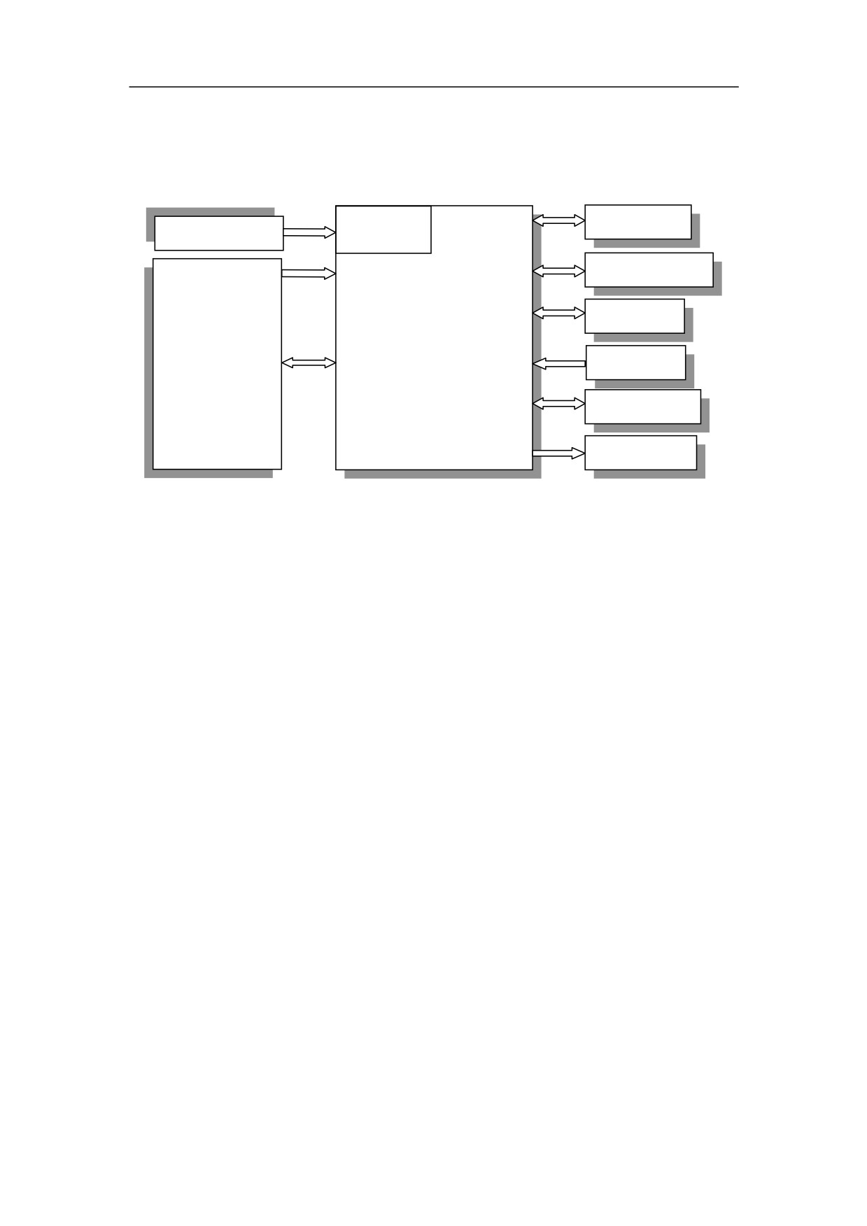
This section shows the total connection diagram of HNC-180.
AC220/DC
XS1-XS3
Feed device
AC220V Power
24V, 5V
Spindle encoder
XS15
XS6
○ Keyboard
XS5
Spindle unit
XS14
XS7
On-off input
○ USB
XS8
Handheld unit
On-off output
XS9
Figure 2-1 Total Connection Diagram
Note:
(1) Interfaces are all optional except that of power supply.
(2) As it is shown Figure 2-1, HNC-180 controls various types of feed units through
XS1-XS3.
(3) The type of feed units can be same or not. Up to three feed axes can be
connected.
8
2.2 Dimension
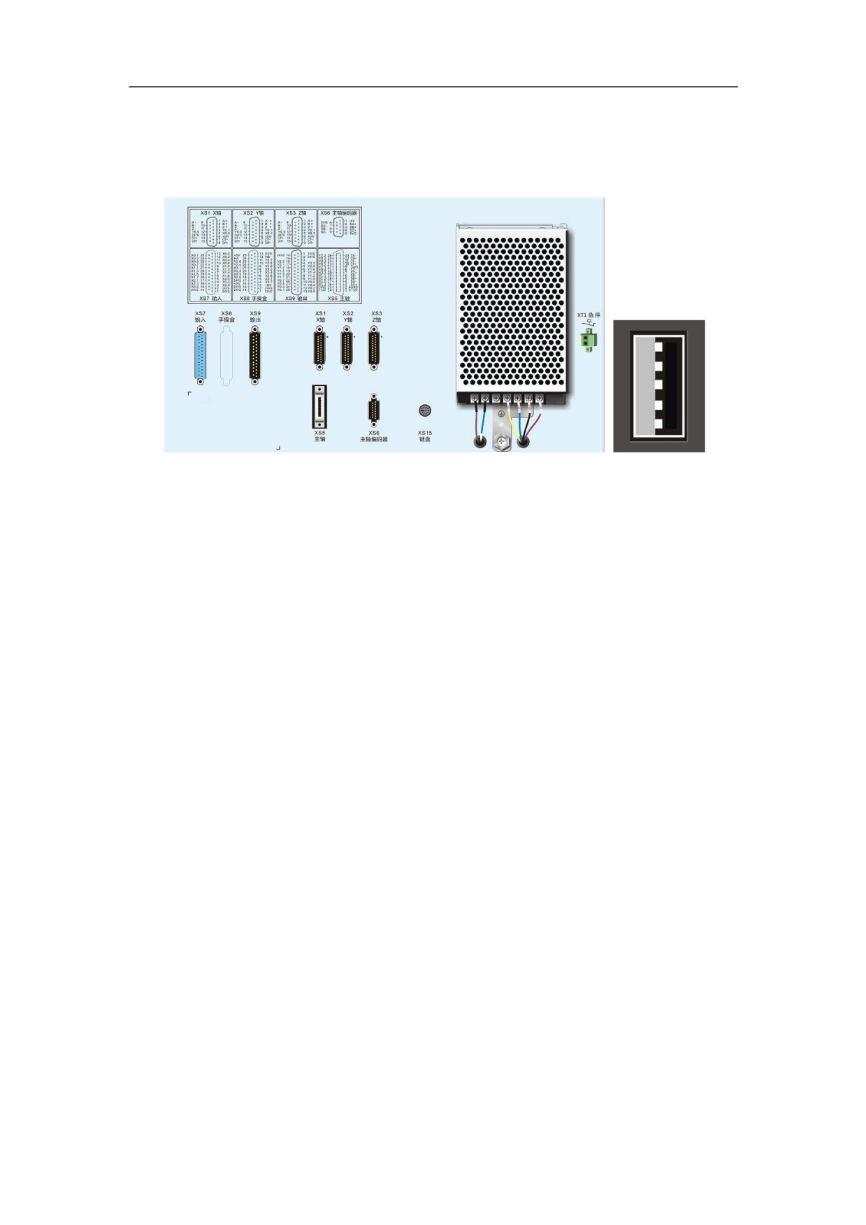
This section shows the interface of HNC-180.
Figure 2-2 Interface of HNC-180
XS1, XS2, XS3: feed axis control interface
XS5: spindle control interface
XS6: spindle encoder interface
XS7: PLC input interface
XS8: handheld unit interface
XS9: PLC output interface
XS14: USB interface
XS15: keyboard interface
XT1: Emergency stop
9
2.3 Power Supply Connection
2.3.1 General Requirement
NC device: AC220V 50W, or DC24V/5V;
Cables: Shielded cables or twisted cables;
PLC power: If DC24V power supply is adopted, the power capability depends on PLC
bits and the number of components with DC24V, such as relay, electromagnetic valve
etc. It is noted that PLC power must be grounded with the signal of PLC interface of
NC device. If DC24V power supply is required for brake on Axis Z and
electromagnetic valve, it is better not to share the power with PLC power preventing
the interference from the electromagnetic valve.
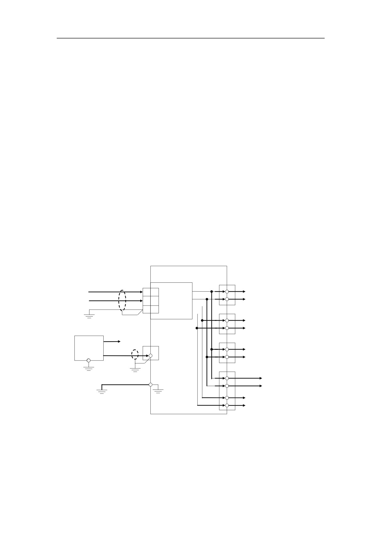
As it is shown in Figure 2-3, XS1, XS2, XS3 provides DC24V power supply to PLC
on-off components of feed devices. XS6 provides DC5V power supply to spindle
encoder. XS5 provides DC24V power supply to PLC on-off components of spindle unit.
XS8 provides DC24V and DC5V power supply to PLC on-off components of handheld
unit and manual pulse generator, respectively.
HNC-180
XS1,
XS2, XS3
+24V
6
NC power
+24V
Feed device
AC220
24VG
13
PLC power
DC24V: 1A
24V
+5V
DC5V : 6A
5VG
XS6
1
+5V
Spindle encoder
6
5VG
power
+24V
external devices
PLC power
XS5
(DC24V)
XS7, XS9
3
Spindle unit
+24V
DC24V
24VG
1,
2, 14
2,
8, 10
PLC power
24V
XS8
3,
16
+24V
Handheld
1,
2, 14, 15, 17
PLC power
24V
Casing ground
25
+5V
MPG
13
power
5VG
Figure 2-3 Power supply of HNC-180
The power of NC device is only 75W. Respectively, DC24V and DC5V provide 1A
output and 6A output. It can only provide DC24V 1A and DC5V 1A to XS1, XS2, XS3,
XS4, XS5, XS7. Please use additional power supply grounded with NC power, if the
power of the mentioned interfaces of the connected devices is higher than NC power.
10
2.3.2 Grounding
-
Protective Grounding
The ground wire of power supply is connected with PE interface of NC
device. An additional copper ground wire at least 2.5 mm2 shall be taken as
the ground wire and connected with PE interface of NC unit, since the
ground wire of the power cable is thin.
-
Signal Grounding
As it is shown in Figure 2-3, the ground wire of external PLC power supply
shall be connected with pin 1, 2, and 14 on XS7 and XS9. Otherwise, NC
unit cannot control those components or receive signals by on-off outputs.
11
2.4 Installation Requirements for Cabinet
¾ The cabinet must prevent from dust, coolant and organic liquor.
¾ In the design of cabinet, the distance between the rare cover of CNC device and case
should not be less than 20cm. Ensure that the temperature difference of case should
not be higher than 10°C, when the temperature in the cabinet is climbing up.
¾ Install a fan in the cabinet to guarantee the ventilation.
¾ The display panel must install where the coolant cannot be sprayed.
¾ Try to reduce the external electric interference sending to CNC device as much as
possible.
12
2.5 Design of Electromagnetic Compatibility
NC device shall be accorded with the requirement of electromagnetic compatibility in
GB8832-1999.5 “The general-purpose technical conditions for NC system design‖.
Electromagnetic Compatibility (EMC) refers to
-
EMC level of electrical equipments shall not be higher than the permitted level in
the expected working environment.
-
The anti-interference ability of device shall be strong enough to ensure working
normally in the expected working environment.
Based on the design of EMC, the following steps must be applied to ensure the
product reliability:
¾ Keep away from the devices producing the interference.
¾ Use the isolated transformer for power supply.
¾ The components in the cabinets should be installed and wired separately by
the strong or weak power.
¾ The shield should be grounded at the entrance into the cabinet.
¾ The power cables and feedback cables of drive motors and spindle drive
motors are directly connected to drive units, skipped the terminals.
¾ Use the shielded cables for the signal wires, such as position feedback wires,
command given wires, and communication wires. The cross section area of every
single lead shall not be less than 0.2 mm2. It is better to use the double-twisted,
double-shielded cables.
¾ Multi-core and twisted are all used in the power lines of on-off terminal boards
and encoder feedback shielded cables to improve the interference capability of
components.
¾ The shell of components must be grounded reliability.
13

3 Interfaces
3.1 Connection to Drive Units
HNC-180 contains the axis control interface with pulse+direction, bidirectional pulse,
or hermite pulse, and feedback interface to control the servo drive and step drive unit.
3.1.1 Interface Description of XS1, XS2, XS3
The pulse interface uses pulse signal and sends position command to control different
kinds of step motor drive and servo drive with pulse interface. It is characterized as
universal interfaces, strong anti-interference ability, and zero drift. However, the
closed loop should be done in drive unit.
There are three pulse axis interfaces (XS1, XS2, and XS3) on HNC-180.
(1) Signal Definition
XS1~XS3 (DB15 PIN)
8:DIR-
15:DIR+
7:CP-
14:CP+
6:+24V
13:24VG
5:X0.*
12:Y0.0
4:Y0.1
11:Z-
3:Z+
10:B-
2:B+
9 :A-
1:A+
Figure 3-1 Interface of XS1~XS3
Table 3-1 Description of XS1~XS3
Signal
Description
A+, A-
feedback signal of encoder phase A
B+, B-
feedback signal of encoder phase B
Z+, Z-
feedback signal of encoder pulse Z
Power output DC24V(it is to supply the power for I/O on
+24V, 24VG
servo.)
Y0.0
reset (logic Address:Y0.0)
Y0.1
enabled (logic Address:Y0.1)
*:
0,
1,
2 stand for axis X, Y, and Z axis are ready
X0.*
respectively.
CP+, CP-
command pulse output (phase A)
DIR+, DIR-
command directional output (phase B)
14
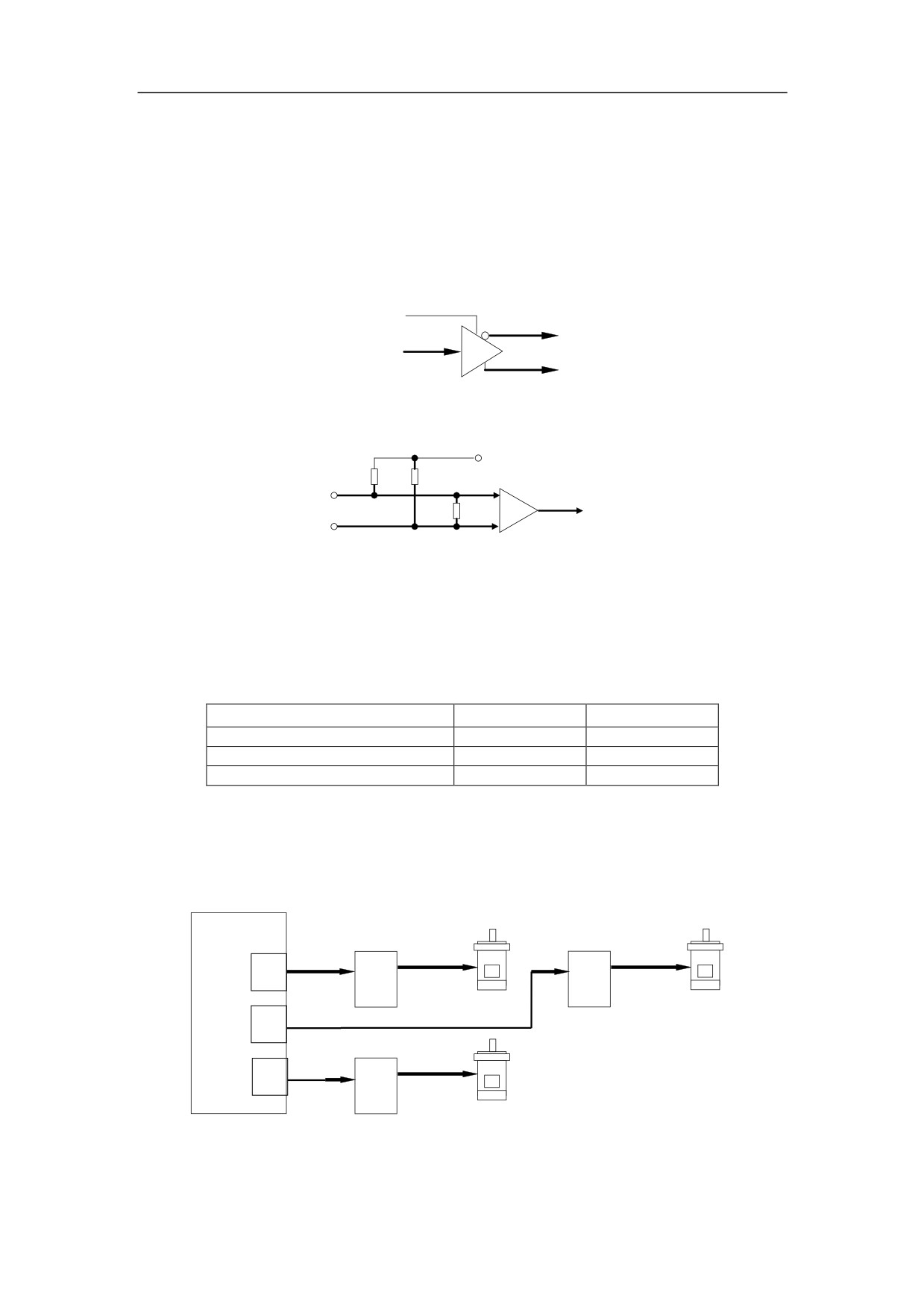
(2)
Technical Specification
-
Maximum pulse frequency: 800KHZ
-
24V power supply: 200mA
-
Encoder signal: RS422 level
(3)
Equivalent circuit
-
Pulse command output
VCC
CP-(DIR-)
CP(DIR)
CP+(DIR+)
Figure 3-2 Pulse command output of equivalent circuit
-
Encoder Input
+5V
10K
10K
A+
+
(B+, Z+)
100
A(B,Z)
A-
-
(B-, Z-)
Figure 3-3 Encoder input of equivalent circuit
(4)
Pulse type
The type of pulse output (pulse+direction, bidirectional direction, and alternating pulse)
can be set by parameters. For more detailed information, please refer to Chapter 4.
Table 3-2 Pulse Type
Pulse Type
CP
DIR
mode 1: pulse+direction pulse
pulse
direction
mode2: bidirectional pulse
positive pulse
negative pulse
mode3: hermite pulse
phase A
phase B
3.1.2 Connection to Stepper Motor Drive Unit
Up to three step motor drives can be connected to HNC-180 through XS1~XS3.
Figure 3-4 shows the overall connection to step motor drive.
HNC-180
Step drive 1
Step drive 2
motor power
motor power
XS1
pulse
Step motor 1
Step motor 2
XS2
pulse
Step drive 3
XS3
pulse
motor power
Step motor 3
Figure 3-4 Overall connection to step motor drive
15
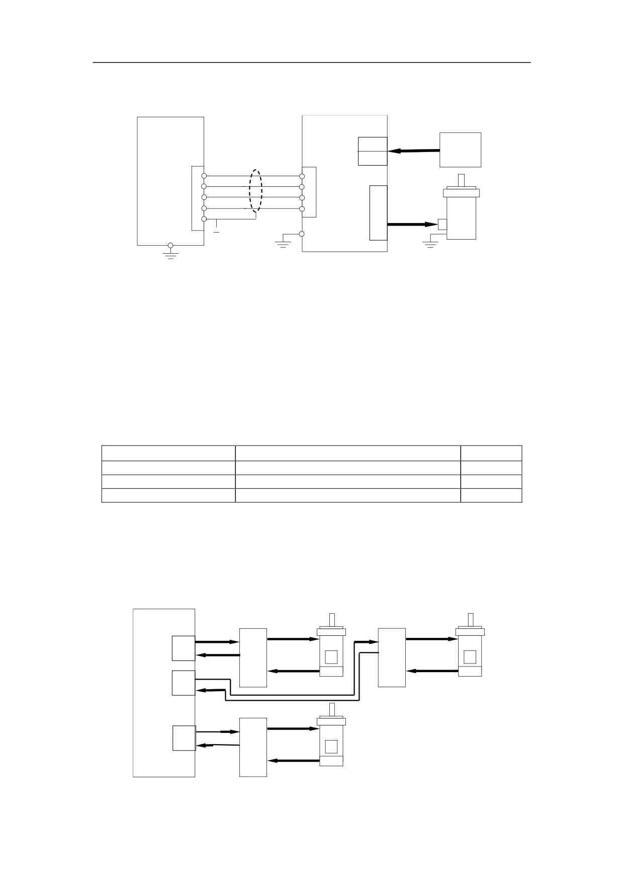
Figure 3-5 shows an example of the connection to SH-50806A (five phases mixed
step motor).
HNC-180
Step drive
drive transformer
AC80
drive power
AC 1P
XS1~XS3
CNI/F
AC80
380/80
shielding
CP+
CW+
14
3
SH-50806A
CP-
CW-
7
4
A
DIR
CCW
15
5
B
DIR-
CCW-
C
8
6
D
motor power
13 GND
E
FG
Step motor
Figure 3-5 Connection to SH-50806A
The other types of step drive can be connected to HNC-180 through I/O. For the
detailed connection, please refer to the relevant manual of drive. If DC24V is
independent, it shall be grounded with I/O of DC power. A relay is required if I/O
interfaces of step motor drives and NC unit are not matched (the type of NC PLC
interface is NPN).
When using step motor, the operator can use the following table to set the parameters.
For detailed information, please refer to Chapter 4 and Chapter 5.
Table 3-3 Parameters related to stepper motor
Parameter
Description
Value
Stepper motor type
45: with feedback; 46: without feedback
45/46
Shoot of Stepper Motor
Actual shoot of stepper motor
4, 6, 10…
Stepper motor
0: no; 1: yes
0, 1
3.1.3 Connection to Servo with Pulse Interface
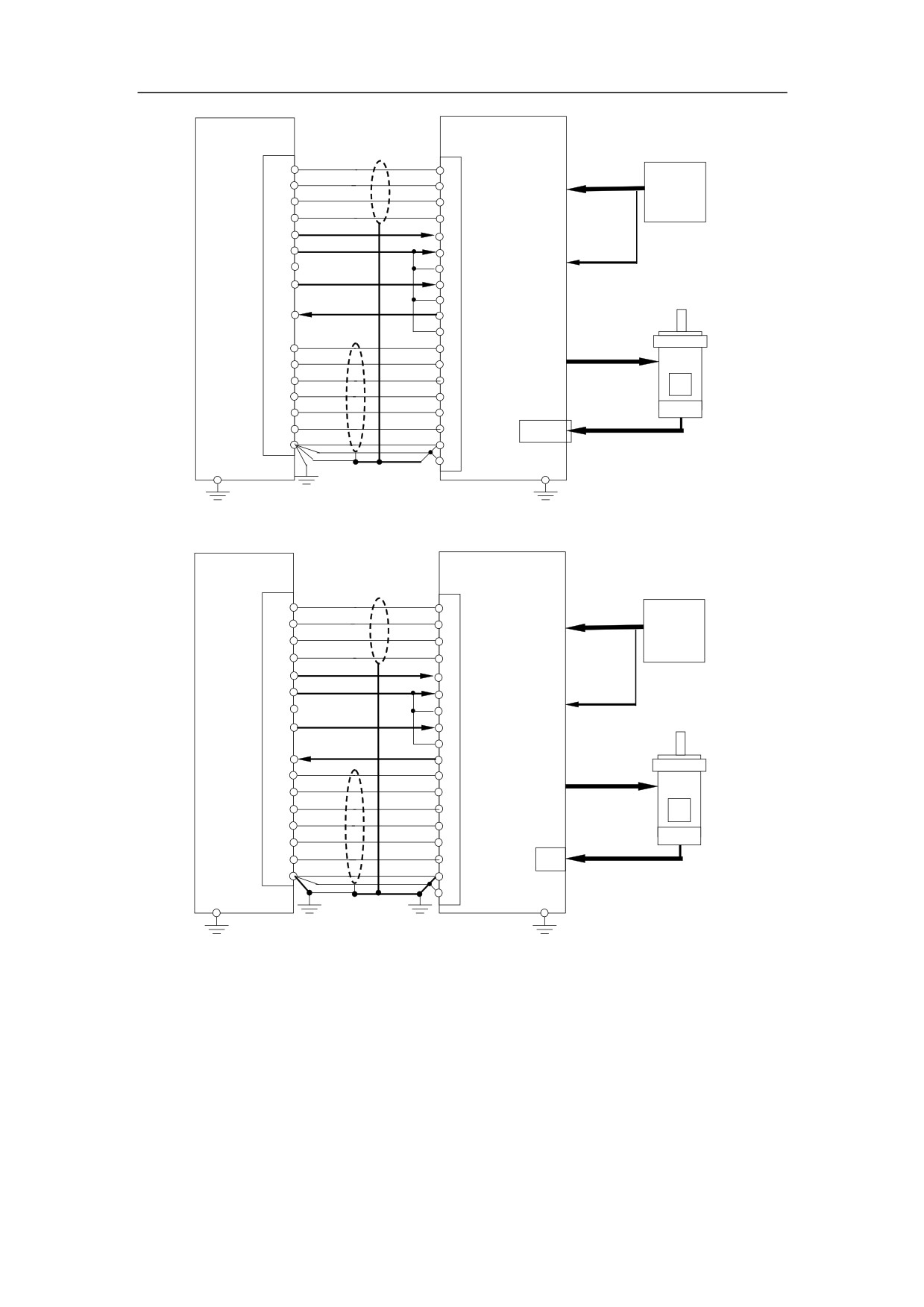
Up to three servos can be connected to HNC-180 through pulse interface of XS1~XS3.
Figure 3-6 is the overall connection between NC device and servo with pulse interface.
Figure 3-7 and 3-8 are the two examples of connection to servo with pulse interface.
HNC-180
Servo Drive 1
Servo Drive 2
motor power
motor power
pulse
XS1
Position feedback
Encoder
feedback
Encoder
feedback
pulse
XS2
Servo Motor 1
Servo Motor 2
Position feedback
Servo Drive 3
pulse
motor power
XS3
Position feedback
Encoder
feedback
Servo Motor 3
Figure 3-6 Overall connection between NC device and Servo with pulse interface
16
HNC-180
≤15m
Servo Drive
XS1~XS3
CNI/F
shielding
CP+
PULS
L1
14
3
Power
CP-
PULS
AC 3P
7
4
Panasonic
L2
DIR
SIGN
15
5
380/200
MSDA103D1A
L3
DIR-
SIGN
8
6
+24V
Servo
Servo
6
7
CO
13
24VG
8
CWL
r
supply
transformer
12
Y0.0
9
CC
t
Y0.1
SRV-O
2
4
34
SRV-RD
X0.*(*:0,1,2)
5
35
SRV-RD
41 COM-
U
1
A+
OA+
21
Motor
V
A-
OA-
9
22
W
B+
OB+
2
48
B-
OB-
P
10
49
Encoder
Z+
OZ+
3
23
feedback
Z-
OZ-
11
24
CN SIG
GND
GND
13
13
Servo
25
Panasonic
MSMA102D1C
Figure 3-7 Connection to Panasonic MINAS A series
HNC-180
≤15m
Servo Drive
XS1~XS3
1CN
shielding
CP+
PULS
14
7
L1
Power
CP-
*PUL
AC 3P
7
8
Yasukawa
L2
DIR
SIGN
15
11
380/200
SGDB-30ADG
L3
DIR-
*SIG
8
12
6
+24V
47
+24
Servo
Servo
24VG
13
42
P-OT
r
supply
transformer
Y0.0
12
43
N-O
t
4
Y0.1
4
S-ON
30
SRV-RDY-
X0.*(*:0,1,2)
5
29 SRV-RDY+
U
A+
PAO
Motor supply
1
33
V
A-
*PA
9
34
W
B+
PBO
2
35
B-
*PBO
P
10
36
Encoder
Z+
PC
3
19
feedback
Z-
*PCO
11
20
2CN
GND
SG
Servo motor
13
1
50
Yasukawa
SGMG-30A2ABG
18NM no keys
Figure 3-8 Connection to Yasukawa SGDB
The following list is the basic conceptions related to servo with pulse interface:
1. Position closed loop is constructed within servo driver rather than NC device.
2. Position feedback signals of pulse interfaces are only used for position monitoring,
not for position closed loop.
3. To construct fully closed loop control, a servo driver with fully closed loop interface
must be used.
17
4. Servo controller parameters should be set in servo driver. Please refer to the
related manuals of the servo driver.
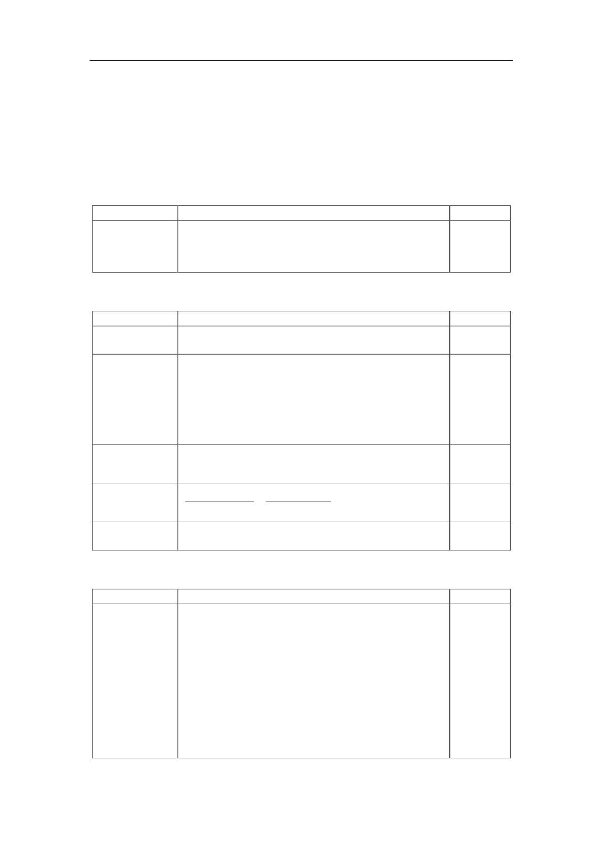
The following table is the list of parameters related to servo with pulse interface. For
more detailed information, please refer to Chapter 4 and Chapter 5.
Table 3-4 List of parameters related to servo with pulse interface
-
Machine Parameters
Parameter
Description
Value
0: unidirectional pulse,
0/1/2
1: bidirectional pulse,
Pulse output
[10000]
2: Hermite pulse
(default)
It shall be consistent with the setting of servo drive.
-
Servo Parameters
Parameter
Description
Value
45: with feedback
Servo type
45/46
46: without feedback
It is used in the alarm message--―too much track
error‖ (unit: μm). If the value is 0, it means that this
alarm function is deactivated. It is used according to
0~65535
Maximum
the highest speed and the lag performance of servo
[12000]
Track Error
loop. In general, the following formula is used:
(default)
max.speed*(10000-position.loop.feedforward.coeffici
ents*0.7)/proportion coefficients of velocity loop/3.
It refers to the number of pulses which NC can get
0~65535
Motor
from each revolution of the motor. It is usually set as
[10000]
revolution
pulses of position encoder of servo motor * 4.
(default)
0~65535
E-gear(NC)
Egear(NC)
NC command
[4:1]
E-gear(Servo)
Egear(Servo)
Servo feedback
(default)
0: no
Stepper motor
0/1
1: stepper motor
-
Axis Parameters
Parameter
Description
Value
It refers to the maximum offset when setting C.S.
(unit: μm). It depends on the motor size, the
performance and load of drive unit. It is usually
10~50. If this parameter is too small, the system
would be held. If it is too large, the machining
0~100
Positioning
precision would be affected. Generally, the bigger the
[20]
tolerance
machine, this value is larger. The worse the precision
(default)
and transmission, the value is larger.
If the stepper motor is used, this value can be set as
integral times each step’s pulses.
If this value is less than backlash, the system would
be held when the axis is moving backwards.
18
3.2 Connection to Spindle device
Different kinds of spindle can be connected to HNC-180 by XS5 to implement CW
rotation, CCW rotation, spindle orientation, speed regulation. Spindle encoder can
also be connected by XS6 to implement threading of turning and grid tapping of
milling.
3.2.1 Relevant Interfaces
3.2.1.1Spindle Interface XS5
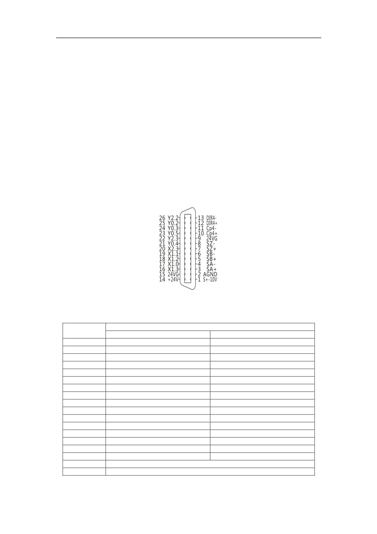
As it is shown in Figure 3-9, XS5 includes the outputs of spindle speed analog voltage
and PLC I/O.
XS5(DB26 PIN)
Figure 3-9 Interface of XS5
Table 3-5 Description of XS5
Description
Signal
Turning
Milling
+24V, 24VG
PLC power DC24V
PLC power DC24V
X1.0
Tool 1
Spindle orientation done
X1.1
Tool 2
Spindle speed arrived
X1.2
Tool 3
Zero spindle speed
X2.3
Spindle alarm
Spindle alarm
Y0.2
Spindle CW rotation
Spindle CW rotation
Y0.3
Spindle CCW rotation
Spindle CCW rotation
Y0.4
Spindle Mode Switch
Spindle Mode Switch
Y0.5
U6
Spindle orientation
Y2.2
Spindle Reset
Spindle Reset
Y2.3
Spindle Enabled
Spindle Enabled
A+, A-
Feedback signal of phase A
Feedback signal of phase A
B+, B-
Feedback signal of phase B
Feedback signal of phase B
Z+, Z-
Feedback signal of phase Z
Feedback signal of phase Z
CP+, CP-
Command pulse output (phase A)
Command pulse output (phase A)
DIR+, DIR-
Command pulse output (phase B)
Command pulse output (phase B)
AOUT
Spindle analog command: -10~+10V output
GND
Analog output grounding
19
The characteristics of interface:
-
PLC I/O
This PLC I/O is connected to the same name of I/O on XS7 and XS9 in parallel. For
more information, please refer to section 3.4.
-
Spindle speed analog voltage output
Voltage: -10V~+10V
Load current: max. 10mA
The following table shows some I/O related to spindle gear control, which are on XS7
(PLC input) and XS9 (PLC output).
Table 3-6 I/O related to spindle gear control
Description
Signal
Interface
Pin
Milling
Turning
Inputs
X1.0
Spindle orientation done
Tool 1
9
X1.1
Spindle speed arrived
Tool 2
21
XS7
X1.2
Spindle zero speed
Too 3
8
X1.3
Spindl ready
Tool 4
20
Outputs
Y0.2
Spindle CW rotation
Spindle CW rotation
12
Y0.3
Spindle CCW rotation
Spindle CCW rotation
24
XS9
Y0.4
Spindle mode switch
Spindle mode switch
11
Y0.5
Spindle orientation
U6
23
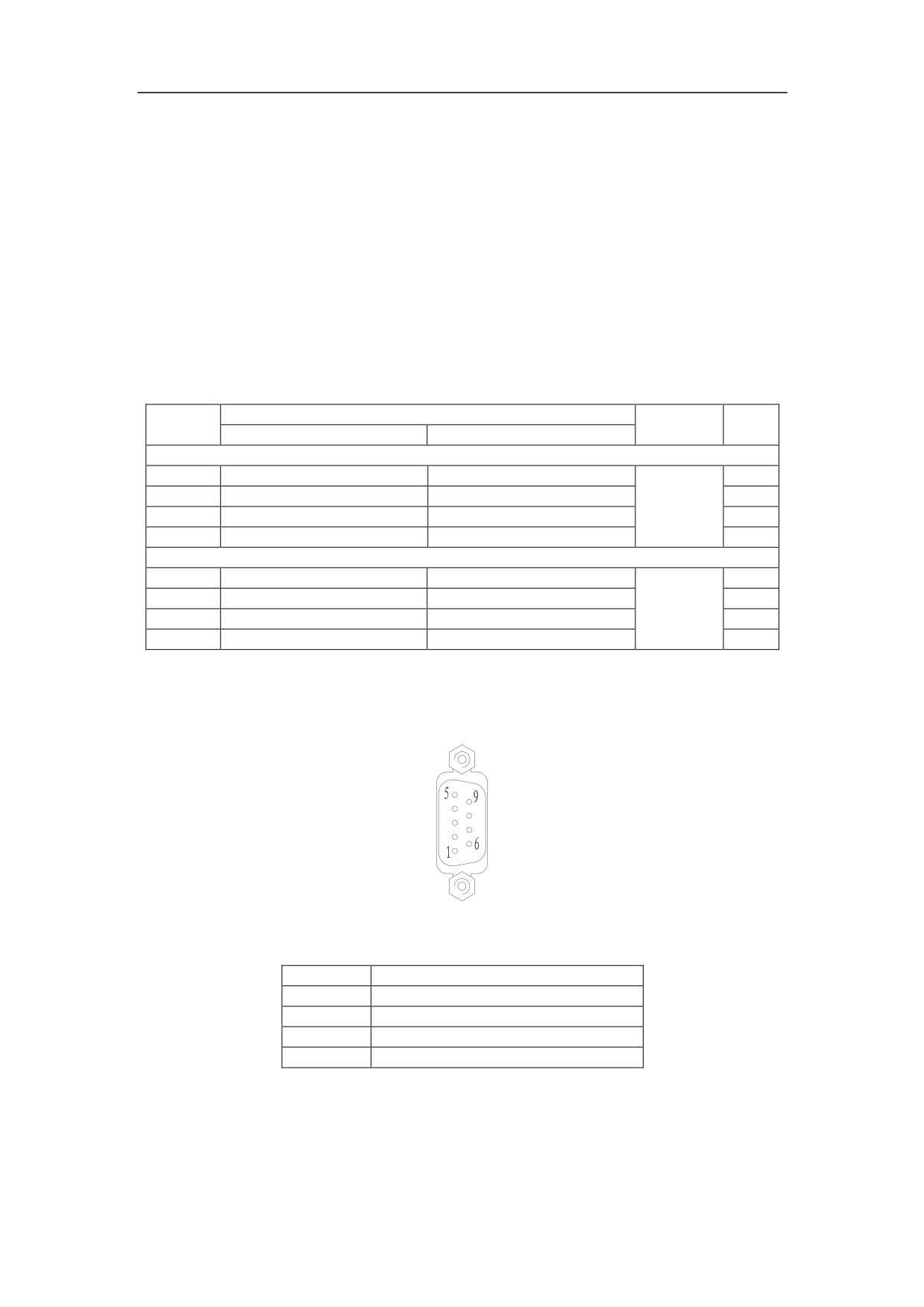
3.2.1.2Spindle Encoder XS6
XS6 (DB9 PIN)
5:5VG
9:SZ-
4:SZ+
8:SB-
3:SB+
7:SA-
2:SA+
6:5VG
1:+5V
Figure 3-10 Interface of XS6
Table 3-7 Description of XS4
Signal
Description
SA+, SA-
Spindle encoder phase A signal
SB+, SB-
Spindle encoder phase B signal
SZ+, SZ-
Spindle encoder pulse Z signal
+5V, 5VG
Power DC5V
The characteristics of interface:
-
Interface of spindle encoder
Power: +5V, max. 200mA
Encoder signal: RS422 level
20
3.2.2 Spindle Start and Spindle Stop
The spindle start and stop are controlled by PLC. Y0.2 and Y0.3 are to control spindle
CW/CCW rotation and stop. In general, it is activated by connection. If Y0.2 is on, the
operator can control the spindle CW rotation. If Y0.3 is on, the spindle CCW rotation
can be controlled. If none of them is on, the spindle stops rotation.
The direction of some spindle rotation depends on the polarity (positive/negative) of
spindle speed signal. In this case, Y0.2 (spindle CW signal) can be used as spindle
enabled control, and the spindle CCW signal is not used.
Some spindle unit contains X1.1 (spindle speed arrived) and X1.2 (zero spindle
speed), so that it can monitor the spindle rotation in PLC. For the turning machine, the
spindle encoder is used to monitor the spindle rotation.
3.2.3 Spindle Speed Control
Analog output (AOUT) in XS5 is to control spindle revolution. The output range is
-10V~+10V. Y0.2 and Y0.3 control the direction of spindle rotation.
3.2.4 Spindle Orientation Control
In the milling machine, spindle orientation function is implemented by the spindle drive
units with spindle orientation function. Y0.5 is spindle orientation command, and X1.0
is the signal when spindle orientation is done.
3.2.5 Spindle Gear Control
Spindle gear can be controlled by PLC. Please refer to Table 3-6.
3.2.6 Connection to Spindle Encoder
The spindle encoder can be connected by XS5 to implement thread cutting, tapping
etc. Two types of spindle encoder can be used: the difference TTL square-wave, and
single-polar TTL square-wave.
Generally, the difference encoder is recommended to ensure the reliability during
long-distance transmission and anti-interference ability. For the detailed connection,
please refer to section 3.2.1.2.
The specification of spindle encoder:
-
+5V power (within 200mA, use external power supply if it is higher than 200mA)
-
TTL level output
-
Difference o utputs: A, B, Z
21
3.2.7 Connection Example―Three-phase Asynchronous Motor
If the asynchronous motor without regulation device is taken as spindle motor, the
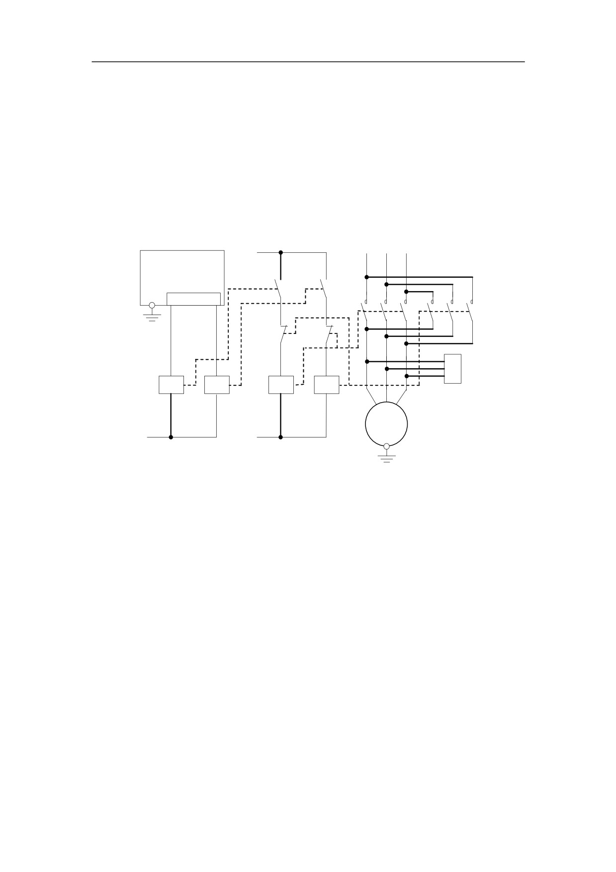
spindle rotation (CW and CCW) and stop can be controlled by the outputs of NC
device with the help of the relay and contact. As it is shown in Figure 3-11, KA3 and
KM3 are to control the motor CW rotation. KA4 and KM4 are to control the motor
CCW rotation. Spindle gear can be added to implement step speed regulation. An
external spindle encoder can be used to implement thread cutting or grid tapping.
Note: The single-phase arc-extinguisher of contact is not shown in the figure.
Contact power
U11 V11 W11
HNC-180
XS5
25
24
Y0.2
Y0.3
RC1
KA3
KA4
KM3
KM4
U1
V1
W1
Arc extinguisher
U V W
Spindle motor
+24V
Contact power
Figure 3-11 Connection example—Three-phase Asynchronous Motor
3.2.8 Connection Example―Spindle Drive
Generally, the servo drive includes AC frequency converter and spindle amplifier
(characteristics: a broader speed regulation and the better low speed-torque). The
signal of AOUT (-10~+10V) on XS5 can define the speed of spindle drive. Therefore,
the non-step spindle regulation can be done within the reasonable range. Spindle
rotation (CW and CCW), spindle stop, running status of spindle can be controlled by
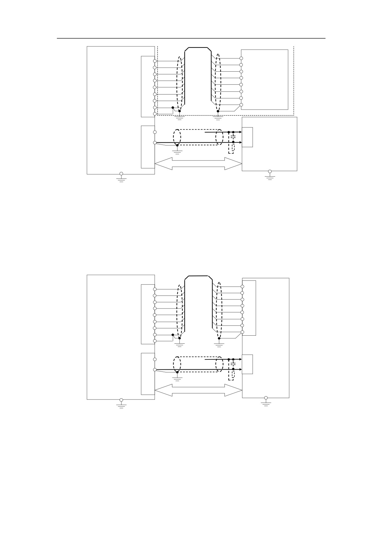
I/O. The connection is shown in Figure 3-12.
If AC frequency converter spindle is used, a mechanical gear should be used to be in
the range of low speed-torque and speed regulation.
22
XS6
SA+
A+
2
SA+
SA-
A-
7
SA-
<15m
SB+
B+
3
SB+
Spindle
SB-
B-
8
SB-
SZ+
Z+
Encoder
4
SZ+
SZ-
Z-
9
SZ-
+5V
+5V
1
+5V
5VG
0V
6
5VG
HNC-180
5
5VG
XS5
Speed Control interface
<15m
9
DAS+
Speed control
-10~+10V
8
DAS-
signal
-10~+10V
Spindle drive
Control and status feedback
Such as spindle CW/CCW rotation,
spindle speed arrived, alarm, etc.
Figure 3-12 Connection to spindle drive (if there is not encoder, the contents in the dotted line is nothing)
As it is shown in Figure 3-12, spindle speed/position feedback is done by the external
spindle encoder. Some spindle drive contains the similar motor speed/position output
interface of encoder. Spindle speed/position feedback can be directly got from spindle
drive, if the transmission ratio of spindles to spindle motors is 1:1 (Figure 3-13).
XS6
SA+
A+
2
SA+
SA-
A-
7
SA-
<15m
speed/position
SB+
B+
3
SB+
feedback
SB-
B-
8
SB-
output interface
SZ+
Z+
4
SZ+
SZ-
Z-
9
SZ-
+5V
+5
1
+5V
5VG
0V
6
5VG
HNC-180
5
5VG
Spindle drive
XS5
<15m
Speed control Interface
9
DAS+
interface
Speed control
signal
-10~+10V
8
DAS-
-10~+10V
Control and status feedback
such as spindle CW/CCW rotation,
spindle speed arrived
Figure 3-13 Connection to spindle drive with feedback output interface
23
//////////////////////