WT9 Dynamic LSA. AIRCRAFT MAINTENANCE MANUAL (AS-AMM-01-000, 22. 05. 2017) - page 40
 

  Index      Manuals     WT9 Dynamic LSA. AIRCRAFT MAINTENANCE MANUAL (AS-AMM-01-000, 22. 05. 2017)


Search            copyright infringement  


Content      ..     38      39      40      41     ..


WT9 Dynamic LSA. AIRCRAFT MAINTENANCE MANUAL (AS-AMM-01-000, 22. 05. 2017) - page 40


Effectivity:

 ALL 

28. 04. 2021


POWER PLANT 
- GENERAL 


  Right carburettor 

  N/A 

  Left carburettor 

  Bracket 

  Left intake manifold 

10 

  Secure clamp 

  Bolt M10 x 110 

11 

  Bolt 

  Bolt M10 x 10 

12 

  Bolt 

  Magnetic plug 

13 

  Bolt of the pressure regulator 


Spring washer ø10


14 

  Banjo fitting 

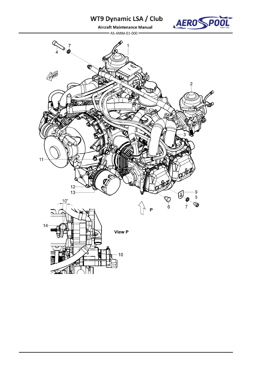
Fig.  71-5  New Engine 


ENGINE ATTACHMENT 


POWER PLANT 

- GENERAL 

(2)  Engine installation: 

Advance preparation of the new engine: 

(a)  Remove  carburettors  (1;  2,  Fig.  71-5)  (see  Rotax  Maintenance 

Manual). 

(b)  Remove left intake manifold (3) (see Rotax Maintenance Manual). 
(c)  Remove  the  bolt  (4)  from  top  right  engine  mount  attachment  point 

together with washer (7). 

(d) 

Drill holes ø1

.6 mm for lockwire on bolts (10; 11; 12). 

(e)  Check magnetic plug (6) for foreign objects. Clean it and refit. Tighten 

it to torque 25 Nm. Secure the magnetic plug (6) with lockwire. 

WARNING: 

IF  METAL  CONTAMINATION  IS  FOUND  ON  PLUG  
(FIG.  12-4,  CHAPTER  12-10),  CONTACT  AIRCRAFT 
MANUFACTURER! 

(f) 

On the starter secure the clamp (10, Fig. 71-5) with lockwire. 

(g)  On  oil  pump  secure  the  bolt  of  the  pressure  regulator  (13)  

with lockwire. 

(h) 

On  oil  pan,  loosen and  turn  the  banjo  fitting  (14) approximately 10° 

clockwise  (in  direction  towards  propeller).  Tighten  the  banjo  bolt  
to torque 35 Nm and secure it with lockwire. 

(i) 

On engine gear, put the bracket (9), washer (7) and tighten bolt (5). 

(j) 

Install  the  baffle  for  cylinders  cooling  on  engine  for  towing  version  
of aircraft (Chapter 75-20). 

Connecting engine systems to engine: 

(k)  Lift engine with hoist, put engine on engine mount and simultaneously 

connect upper exhaust pipes (2; 3, Fig. 78-2) to engine. 

(l) 

Install distance rollers (9,  Fig.  71-4), washers (10) and tighten bolts  
(6; 7; 8) to torque 40 Nm. 

(m)  On drip trays (4; 5), clean holes i

n the hose sockets with drill ø

3 mm; 

carefully  bend  hose  socket,  30°  to  the  rear,  20°  to  the 

centre  

as in (Fig. 71-6). 

(n) 

Carry  out  the  same  on  the  right  drip  tray  30°  to  rear  and  20° 


to the centre.


Effectivity:

 ALL 

28. 04. 2021


POWER PLANT 
- GENERAL 


Fig. 71-6  Left drip tray 


(o)  Install  and  connect  intake  manifold  (2,  Fig.  71-4),  lubricated  seal 

papers (3); drip trays (4; 5), carburettors (1) (see Rotax Maintenance 
Manual),  and  install  airbox  (Chapter  71-60)  for  correct  positioning 
intake manifolds with carburettors. 

(p)  Remove Airbox (Chapter 71-60). 
(q)  Install lower exhaust pipes (4; 5, Fig. 78-2) and secure upper exhaust 

pipes (2; 3) (Chapter 78-10). 

(r)  Connect  oil  system  (13,  Fig.  71-4)  with  oil  pump  and  oil  pan,  

by  connecting  hoses  (14;  15)  and  securing  with  safety  clamp  (19), 
gasket  rings  (18)  and  elbow  (16)  with  the  adapter  (17);  tighten  
to torque moment 30 Nm and secure with lockwire. 

(s)  Shorten the water hose (1, Fig. 71-7) about 15 mm and water hose (2) 

pull out, so that the hose socket output of expansion tank was parallel 
with upper strut of engine mount. 

(t) 

Connect cooling system to engine, by connecting hoses (14; 17; 19, 
Fig. 75-2) and securing them with hose clamps (6; 27). 

(u)  Install air hose (22, Fig. 21-5 (Chapter 21-40). 
(v)  Connect  the  fuel  hoses  (1;  2;  3;  5,  Fig.  28-7)  to  fuel  pump  

and carburettors (Chapter 28-20). 

(w)  Connect and adjust control cables of throttle controller (20, Fig. 76-3) 

and choke (22) to carburettors (Chapter 76-10). 

(x)  Connect  drain  hoses  (3;  6,  Fig.  71-14)  to  drip  trays  and  fuel  pump 

(Chapter 71-60). 

Connecting electric system: 

NOTE 

See Aircraft Wiring Manual (Doc. No. AS-AWM-01-000). 


ENGINE ATTACHMENT 


POWER PLANT 

- GENERAL 


  Hose 

  Hose 

  Hose 

  Safety clamp 14.5 

  Expansion tank 


Fig.  71-7  Cooling System 

(y)  On  engine  cylinder  head  No.2,  connect  the  grounding  wires  221A  

and 222A. 

(z)  On engine cylinder head No.3 connect the grounding wire 222A. 
(aa)  On engine mount connect wire 221A. 
(bb)  On  SMD-Electronic  module,  remove  the  connectors  from  holder  

and connect wires B30, WH-113B, WH-114B to connectors. 

(cc)  Re-route ground wire from forward grounding point on No.3 induction 

manifold to the inside of the ignition unit to avoid chafing. Route around 
the front between the inlet cables and attach to the rear mounting bolt. 
Apply  on  left  side  of  SMD-Electronic  module  piece  of  pyrojacket  
(fire sleeve) and secure with cable tie (4.8 mm) as required. 

(dd)  On generator, connect wire of generator 220A. 
(ee)  On starter, connect wire of starter 101B. 
(ff)  Near engine fuel pump, connect the connectors of pressure oil sensor 

M101 (red wire with red wire and white wire with white wire). Insulate 
them with shrink tubes. 

(gg)  Near  engine  cylinder  heads  No.2,  No.3  and  near  oil  filter,  connect 

wires of temperature sensors M72 and M73; secure wire connectors 
with shrink tubes. 

(hh)  At  charging  rectifier  located  on  firewall,  connect  wires  of  generator  

YE-106B and YE-107B (2 pcs). 


Effectivity:

 ALL 

28. 04. 2021


POWER PLANT 
- GENERAL 


(ii)  On firewall, connect connector of engine rpm indicator B28. 
(jj)  Insulate  wires  of  ignition  with  pyro  jacket  (fire  sleeve)  coverings 

between intake manifolds 2-4 and 1-3. Secure them with cable ties. 

(kk)  Fix all hoses and cables to prevent movement and abrasion with cable 

ties. 

(ll)  Install Airbox (Chapter 71-60). 
(mm) Install propeller (Chapter 61-10). 
(nn)  Fill with oil (Chapter 12-10). 
(oo)  Fill with coolant and fuel (Chapter 12-10). 
(pp)  Test to verify the task and check: 

  If all systems are connected and secured. 

  Proper connection of cables. 

  Good connection of joints. 

  Disconnect connector of magnetos. Use the multimeter to check 

if  magneto  switches  are  in  OFF  position,  wires  WH-113B,  
WH-114B  with  negative  terminal,  circuit  is  closed.  When  
the  magneto  switches  are  in  ON  position,  wires  WH-113B,  
WH-114B with negative terminal, circuit is open. 

  Torque moments on nuts. 

  If hoses and cables are securely fixed. 

  If all bolts are tight. 

  That no foreign objects remained in aircraft. 

(qq)  Install engine cowlings (Chapter 71-10). 

B.  Engine mount 

Type of maintenance: 

Heavy 

Personnel qualification: 

Independent  certifying  staff  qualified  in  accordance 


with Part-66 or higher. 

Recommended tools, materials, persons and documentation: 

ITEM 

QUANTITY 

Hex key 7 

1 pc 

Wrench 13 

1 pc 

Persons 

Tab. 71-3 Recommended tools, materials, persons and documentation 

(1)  Engine mount removal: 

(a)  Remove engine (Chapter 71-20). 
(b)  Remove drain hoses (Chapter 71-70). 
(c)  Remove  nuts  (7,  Fig.  71-8),  washers  (8),  front  plates  (4)  and  front 

silentblocks (2). 

(d)  Remove the mount (1) from the aircraft. 
(e)  Remove  rear  silentblocks  (2),  spacers  (5)  and  aft  plates  (3)  

from the mount. 

(f) 

Remove bolts (6) from the aircraft.


ENGINE ATTACHMENT 


POWER PLANT 

- GENERAL 

(2)  Engine mount installation: 

(a)  Inspect the engine mount. Look especially for cracks. 
(b)  Inspect silentblocks for damage and cracks. 
(c)  Insert bolts (6, Fig. 71-8) to holes on the firewall. 
(d)  Put  the  rear  plates  (3),  rear  silentblocks  (2)  and  spacers  (5)  

on the bolts (6). 

(e)  Put  the  mount  (1)  in  position  and  put  an  appropriate  support  below  

the mount. 

(f) 

On  bolts  (1)  put  on  silentblocks  (2),  front  plates  (4),  washers  (8),  
and tighten nuts (7) to torque 22.5 Nm. 

(g)  Test to verify the task and check: 

  Torque moments on nuts. 

  That no foreign objects remained in aircraft. 


  Engine mount 

  Spacer 

  Silentblock 

  Bolt M8 x 90 

  Silentblock rear plate 

  Self-locking nut M8 

  Silentblock front plate 


Washer ø8

.4 x 16 x 1.6 

Fig.  71-8  Engine Mount Removal / Installation 


ATTACH FITTINGS 


POWER PLANT 

- GENERAL 

71-40


ATTACH FITTINGS


1.  DESCRIPTION 

There are two attach fittings installed on the engine to which the hoses and wires are 
fixed. 

2.  MAINTENANCE PRACTICES 

A.  Brackets 

Type of maintenance: 

Line 

Personnel qualification: 

Independent  certifying  staff  qualified  in  accordance 


with Part-66 or higher. 

Recommended tools, materials, persons and documentation: 

ITEM 

QUANTITY 

Hex key 8 

1 pc 

Loctite 243 

AR 

Persons 

Tab. 71-4 Recommended tools, materials, persons and documentation 

WARNING 

ENGINE IGNITION MUST BE SWITCHED OFF. 

(1)  Brackets removal: 

(a)  Make sure that the 

IGNITION 

switches are set to 

OFF

(b)  Remove the upper engine cowling (Chapter 71-10). 
(c)  Remove items attached to the brackets (1, Fig. 71-6) 
(d)  Remove bolts (3), washers (2) and brackets (1) 

(2)  Brackets installation: 

(a)  Make sure that the 

IGNITION 

switches are set to 

OFF

(b)  Attach brackets (1, Fig. 71-6) using washers (2), bolts (3) and secure 

by using Loctite 243. 

(c)  Install the upper engine cowling cowling (Chapter 71-10). 


Effectivity:

 ALL 

28. 04. 2021


POWER PLANT 
- GENERAL 


  Bracket 

  Bolt M10 x 16 


Spring washer ø10


Fig.  71-9  Engine Attach Fittings Removal / Installation 


AIR INTAKES 


POWER PLANT 

- GENERAL 

71-60


AIR INTAKES


1.  DESCRIPTION 

Cooling air is received through the two upper engine cowling intakes and is distributed 
to the engine compartment. 
Air intake is located on the left side of spinner. The cold air flows through the ram air 
tunnel  (glued  at  the  lower  engine  cowling),  air  hose,  air  filter  holder  and  air  filter  
to  the  airbox.  The  air  filter  holder  receives  warm  air  from  a  shroud  installed  
on  the  muffler  (Chapter  78)  and  cold  air  from  the  ram  air  tunnel  and  mixes  them 
depending  on  preheating  control  setting. 

CARBUR.  PREHEATING

  controller  

is located on the instrument panel. 

2.  MAINTENANCE PRACTICES 

A.  Airbox and air filter holder 

Type of maintenance: 

Line 

Personnel qualification: 

Independent  certifying  staff  qualified  in  accordance 


with Part-66 or higher. 

Recommended tools, materials, persons and documentation: 

ITEM 

QUANTITY 

Wrench 10 

1 pc 

Special wrench 14 

1 pc 

Screwdriver 5 

1 pc 

Hex key 4 

1 pc 

Hex key 5 

1 pc 

Oetiker pliers- Crimping pliers 

1 pc 

Knife 

1 pc 

Pliers 

1 pc 

Cable tie 2.6 

7 pcs 

Lockwire 

ø

0.8 mm 

AR 

Loctite 243 

AR 

Persons 

Tab. 71-5 Recommended tools, materials, persons and documentation 

WARNING 

ENGINE  IGNITION  MUST  BE  SWITCHED  OFF.  DISCONNECT 
NEGATIVE TERMINAL OF AIRCRAFT BATTERY. 


Effectivity:

 ALL 

28. 04. 2021


POWER PLANT 
- GENERAL 


(1)  Airbox and air filter holder removal: 

(a)  Make sure that the 

IGNITION 

switches are set to 

OFF

(b)  Remove the engine cowlings (Chapter 71-10). 
(c)  Disconnect negative terminal of battery (Chapter 24-30). 

Air filter holder removal: 

(d)  Disconnect  air  hoses  (4;  5,  Fig.  71-10),  by  loosening  hose  clamps  

(13; 14). 

(e)  Disconnect control cable (3) from the air filter holder (2). 
(f) 

Unplug the connector of temperature sensor (21). 

(g)  Remove safety pins (20) and unclip the latches on upper and lower 

side of air filter holder (2). 

(h)  Remove air filter holder (2) with air filter (6). 

Airbox removal: 

(i) 

Disconnect drain hoses (9; 10; 11; 12), by removing cable ties. 

(j) 

Loosen hose clamps (13) on hoses (7; 8). 

(k)  Unscrew nuts (19), remove washers (16; 17; 18) and bolt (15). 
(l) 

Remove the airbox (1). 

(2)  Airbox and air filter holder installation: 

(a)  Make sure that the 

IGNITION 

switches are set to 

OFF

(b)  Thoroughly clean and lubricate all movable parts of the air induction 

system before each assembling (Chapter 12-20). 

(c)  Check and clean air filter (6, Fig. 71-10), check free operation of air 

filter holder (2) and check the air hoses for cracks; if cracks are found 
use new air hoses. 

(d)  Apply two layers of adhesive tape on each end of hoses. 

Airbox installation: 

(e)  Connect airbox (1) with carburettors using hoses (7; 8). 

NOTE 

Hose (7) is longer than hose (8). 

(f) 

Attach the airbox (1) to engine mount (24) by using bolts (15), washers 
(16; 17; 18) and nuts (19). 

(g)  Secure hoses (7; 8) to the airbox (1) by hose clamps (13). 
(h)  Slide drain hoses (9; 10; 11; 12) on airbox (1) and secure them using 

cable ties. 
Air filter holder installation: 

(i) 

Fit clean air filter (6) to the air filter holder (2). 

(j) 

Attach them (2; 6) to the airbox (1), clip two latches and secure them 
with safety pins (20). 

(k)  Connect the temperature sensor connector (21). 
(l) 

Connect the control cable (3) to the air filter holder (2). 


AIR INTAKES 


POWER PLANT 

- GENERAL 

(m)  Connect air hoses (4; 5) and secure them with hose clamps (13; 14).  
(n)  Carry out test and check: 

  If all bolts connections are tight. 

  If hoses are firmly secured and sealed. 

  That the latches are secured with safety pins. 

  Operation  of  air  filter  holder  flaps  (fully  open  and  fully  close 

position). 

  That  no  foreign  objects  remain  in  the  aircraft  or  engine 

compartment. 

(o)  Install the engine cowlings (Chapter 71-10). 


Effectivity:

 ALL 

28. 04. 2021


POWER PLANT 
- GENERAL 


Fig.  71-10  Airbox Removal / Installation (page 1 of 2) 


AIR INTAKES 


POWER PLANT 

- GENERAL 


  Airbox 

14 

  Hose clamp 

ø

50-70 

  Air filter holder 

15 

  Bolt M6 x 18 

  Control cable 

16 

  Washer 

ø

 6.4 x 18 x 1.6 


Air hose ø63 x 420


17 

  Rubber washer 

ø

6.4 


Air hose ø51 x 260


18 

  Washer 

ø

6.4 x 12 x 1.6 

  Air filter 

19 

  Self-locking nut M6 

  Hose 

ø

50 x 60 

20 

  Safety pin 

ø

1.4 

  Hose 

ø

50 x 40 

21 

  Electrical connector 

  Drain hose R 

For information: 

10 

  Drain hose L 

22 

  Ram air tunnel 

11 

  Upper drain hose R 

23 

  Airbox pre-heat exchanger 

12 

  Upper drain hose L 

24 

  Engine mount 

13 

  Hose clamp 

ø

40-60 


Fig.  71-10  Airbox Removal / Installation (page 2 of 2)  

B.  Air filter 

Type of maintenance: 

Line 

Personnel qualification: 

Independent  certifying  staff  qualified  in  accordance 


with Part-66 or higher. 

Recommended tools, materials, persons and documentation: 

ITEM 

QUANTITY 

Air filter 

1 pc / AR 

Air filter oil 

AR 

Persons 

Tab. 71-5 Recommended tools, materials, persons and documentation 

(1)  Air filter inspection / check: 

Check air filter on each inspection or annually for cleanliness. Air filter can 
be cleaned using compressed air and then brushed with air filter oil. Replace 
air filter if necessary. 


Effectivity:

 ALL 

28. 04. 2021


POWER PLANT 
- GENERAL 


C.  Carburettor pre-heat control 

Type of maintenance: 

Line 

Personnel qualification: 

Independent  certifying  staff  qualified  in  accordance 


with Part-66 or higher. 

Recommended tools, materials, persons and documentation 

ITEM 

QUANTITY 

Wrench 10  

1 pc 

Special wrench 14 

1 pc 

Screwdriver 5 

1 pc 

Hex key 4 

1 pc 

Hex key 5 

1 pc 

Solder set 

1 pc 

Knife 

1 pc 

Pliers 

1 pc 

Cable tie 2.6 

7 pcs 

Cable tie 3.6 

5 pcs 

Shrink tube 

ø

4.8 x 2.4 mm 

AR 

Adhesive sealing tape TESA FIX 20 mm 

AR 

Lockwire 

ø

0.8 mm 

AR 

Loctite 243 

AR 

Persons 

Tab. 71-6 Recommended tools, materials, persons and documentation 

WARNING 

ENGINE IGNITION MUST BE SWITCHED OFF. 


AIR INTAKES 


POWER PLANT 

- GENERAL 

(1)  Carburettor pre-heat control removal: 

(a)  Make sure that the 

IGNITION 

switches are set to 

OFF

(b)  Remove the engine cowlings (Chapter 71-10). 
(c)  Unscrew  cable  end  fitting  (1,  Fig.  71-12),  remove  shrink  tube,  

and unsolder thread rod (2). 

(d)  From  the  cockpit,  remove  the  inner  cable  by  pulling  handle  (14)  

and remove the nut (15). 

(e)  Remove parachute container (Chapter 25-60). 
(f) 

In  parachute  compartment,  remove  lockwire  (6)  and  remove  
the control cable (7) from firewall. 

(g)  Remove cable tie (9), unstick adhesive  tape (10), pull green sleeve 

(11).


NOTE 

The ball can drop from green sleeve (10). 

(h)  Unscrew the nut (12), remove washer (13) and pull out control cable 

(7) from central console.


NOTE 

For easier removal use special tool (Fig. 71-11) and hex key 
inserted on control cable end from cockpit side. 


Fig.  71-11 Band Wrench Size 14 


(i) 

In  the  engine  compartment,  unscrew  nut  (3,  Fig.  71-12),  remove 
washers (4) with the nut (3), screw shackle (5). 


Effectivity:

 ALL 

28. 04. 2021


POWER PLANT 
- GENERAL 


(2)  Carburettor pre-heat control installation: 

(a)  Make sure that the 

IGNITION 

switches are set to 

OFF

(b)  Thoroughly clean and lubricate all movable parts of the air induction 

system  before  each  assembling.  Refer  to  lubrication  chart  
(Chapter 12-20). 

(c)  Control cable (7, Fig. 71-12) passes through central console (16). 
(d)  Rotate the control cable (7) so the ball is at the top. 
(e)  Slide washer (13), tighten the nut (12) and secure using Loctite 243. 

NOTE 

For  better  performance  use  special  wrench  (Fig.  71-11)  
and hex key inserted in control cable end from cockpit side. 

(f) 

Insert  the  ball  and  simultaneously  slide  on  the  green  sleeve  
(11, Fig. 71-12): 

  Push  the  green  sleeve  (11)  just  to  first  indication  of  minimal 

resistance. 

  Check for correct operation by pulling and pushing handle; the ball 

must engage with ratchet, movement must not be free. 

(g)  Apply two layers of textile adhesive tape (10) and lock it with cable tie 

(9). 

(h)  Assemble screw shackle (5) with nut (3), washer (4) and bowden end 

(8); put them on control cable (7) and secure them with lockwire (6). 

(i) 

Insert the cable with screw shackle through hole in firewall (17), apply 
washer (4) and screw on the nut (3), secure with Loctite 243. 

(j) 

Secure  control  cable  (7)  with  cable  ties  (3.6  mm)  along  the  length  
as required. 

(k)  Push handle (14) in, leaving a gap of 2 mm (carburettor pre-heating) 

and set air filter holder bellcrank (18) to position with cold air flap fully 
open. 

(l) 

Cut inner wire to correct length, solder thread rod (2), slide shrink tube 
and screw on cable end fitting (1),  and adjust  end fitting to connect 
with nipple on bellcrank. 

(m)  Shrink the shrink tube on thread rod (3). 
(n)  Connect cable end fitting (1) with nipple on bellcrank (18). 
(o)  Carry out test and check: 

  If all bolts connections are tight. 

  Operation of air filter holder flaps (fully open and fully close). 

  That  no  foreign  objects  remain  in  the  aircraft  or  engine 

compartment. 

(p)  Install the engine cowlings (Chapter 71-10). 


Content      ..     38      39      40      41     ..