WT9 Dynamic LSA. AIRCRAFT MAINTENANCE MANUAL (AS-AMM-01-000, 22. 05. 2017) - page 38
 

  Index      Manuals     WT9 Dynamic LSA. AIRCRAFT MAINTENANCE MANUAL (AS-AMM-01-000, 22. 05. 2017)


Search            copyright infringement  


Content      ..     36      37      38      39     ..


WT9 Dynamic LSA. AIRCRAFT MAINTENANCE MANUAL (AS-AMM-01-000, 22. 05. 2017) - page 38


Effectivity:

 ALL 

04. 07. 2019


WINGS 


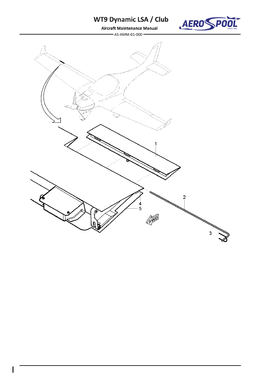
  Trim tab 

  Bracket 

  Hinge rod 

  Right aileron 


Locking wire ø0

.8 mm 


Fig.  57-8  Aileron Trim Tab Removal / Installation 


GENERAL 


PROPELLERS 

61-00


GENERAL


1.  INTRODUCTION 

The  aircraft  can  be  equipped  with  three  blades  fixed  pitch  propeller  EVRA 
PerformanceLine  175/xxx/805.5  or  with  three  blades  in-flight  adjustable  propeller  
KW-31 (EASA.P.177). 

2.  TROUBLESHOOTING 

For troubleshooting of propeller KW-31 follow the instructions in the original equipment 
manuals. 

TROUBLE 

POSSIBLE CAUSE 

REMEDY 

Engine vibration 

Propeller out of balance. 

Examine the propeller. 
If you find damage, 
contact aircraft 
manufacturer. 

The propeller mounting 
bolts are loose. 

Tighten propeller 
mounting bolts to specific 
torque in crosswise 
pattern. 

The spinner attaching 
bolts are loose. 

Tighten spinner attaching 
bolts to specific torque. 

Blade tracking not correct. 

Contact aircraft 
manufacturer. 

Incorrect propeller 
alignment. 

Remove the propeller. 
Install the propeller  
in the correct position. 
Refer to Chapter 61-10. 


PROPELLER ASSEMBLY 


PROPELLERS 

61-10


PROPELLER ASSEMBLY


1.  DESCRIPTION 

A.  EVRA  PerformanceLine  175/xxx/805.5

  is  3-blade  on  ground  adjustable 

propeller with diameter 1.750 m (68.90 in). Its blades have wooden core covered 
with  glass  fabric,  stiffened  with  metal  leading  edges.  Blades  are  fixed  
in  aluminium  hub  that  consists  of  two  parts.  The  lower  hub  (in  contact  
with the engine or gearbox flange) is different from the upper hub. Propeller's hub 
is through a flange attached to engine's propeller shaft. The composite spinner  
is fixed to the spinner flange. 
The halves of hub (lower hub on the engine flange side, upper hub from the front 
side) are marked on their side faces by numbers. It is necessary to synchronize 
them face to face during the final assembly. There must be a small gap between 
the halves of hub that ensures the blades are properly fixed when the hub bolts 
are tightened. 
The lower hub has smaller notches than upper hub for M6 nuts. 
The blades are numbered on the metal part of leading edge with numbers 1 or 2 
or 3. These blades are balanced with the hub so it is very important to respect 
their  position  within  the  hub  (the  blade  No.  1  in  the  hub  slot  No.  1,  the  blade  
No. 2 in the hub slot No. 2...). 
On  the  leading  edge  of  the  blades  there  are  three  marks  (three  lines),  that 
represent the "07 R" 70% of the radius. It is the place where you have to make 

the pitch angle readings of the blades when adjusting the blades. The “07 R” is 

represented by the middle line mark. 

B.  KW-31 (EASA.A.177) 

is a 3-blade electrically operated in flight adjustable aircraft 

propeller  with  diameter  1.726  m  (67.95  in)  diameter.  The  blades  are  made  
of  combination  of  lash  wood  and  composite.  The  propeller  can  be  operated  
in  either  manual  or  with  automatic  mode  as  a  constant  speed  propeller.  
The leading edges are protected by stainless steel stamping. 

NOTE 

For more details refer to 

“UM

-05 EN - User Manual Aircraft Propeller 

Type-Model KW-

31”, 

last valid issue. 


Effectivity:

 ALL 

28. 04. 2021


PROPELLERS


2.  MAINTENANCE PRACTICES 

A.  Propeller EVRA PerformanceLine 175/xxx/805.5 

Type of maintenance: 

Line 

Personnel qualification: 

Independent  certifying  staff  qualified  in  accordance 


with Part-66 or higher. 

Recommended tools, materials, persons and documentation: 

ITEM 

QUANTITY 

Wrench 13 

1 pc 

Screwdriver 

1 pc 

Hex key 4  

1 pc 

Hex key 5  

1 pc 

Hex key 6 

1 pc 

Loctite 243 

AR 

Persons 

Tab. 61-1 Recommended tools, materials, persons and documentation 

WARNING 

ENGINE  IGNITION  MUST  BE  SWITCHED  OFF!  DISCONNECT 
NEGATIVE TERMINAL OF AIRCRAFT BATTERY. 

(1)  Propeller removal: 

(a)  Make sure that the 

IGNITION 

switches are set to 

OFF

(b)  Remove the engine cowlings (Chapter 71-10). 
(c)  Disconnect negative terminal of battery (Chapter 24-30). 
(d)  Remove upper line of spark plugs from the engine. 
(e)  Unscrew bolts (7, Fig. 61-1) with washers (8) and remove the propeller 

spinner (6). 

(f) 

Unscrew and remove nuts (3) and washers (4); hold the propeller (1). 

(g)  Pull  the  propeller  forward;  remove  the  bolts  (2)  with  washers  (4), 

balance weight (5), propeller (1) and flanges (9; 10) from the engine 
flange. 

(h)  Put  the  protective  covers  on  the  propeller  blades  and  store  

the propeller on a safe place so that no damage can occur. 

(i) 

As necessary, disassemble flanges (9; 10), by unscrewing the bolts 
(11) and removing washers (12). 

(j) 

If necessary, unscrew the shear pins (14)  


PROPELLER ASSEMBLY 


PROPELLERS 

(2)  Propeller installation: 

CAUTION 

WHEN 

THE 

NEW 

PROPELLER 

IS 

INSTALLED,  

IT  IS  NECESSARY  TO  CHECK  THE  TORQUE  MOMENTS  
OF BOLTS AFTER FIRST HOUR OF FLIGHT OPERATION! 

(a)  Make sure that the 

IGNITION 

switches are set to 

OFF

(b)  Make  sure  that  the  battery  is  disconnected  and  upper  line  of  spark 

plugs is removed from the engine. 

(c)  Check  the  contacting  areas  of  the  flange  (13,  Fig.  61-1),  flanges  

(9, 10) and the propeller (1). Clear of all impurities. 

(d)  Remove  protective  covers  from  the  propeller  blades  and  carry  out 

visual check of the propeller integrity and condition. 

(e)  If flanges (9, 10) are disassembled, use washers (12) and bolts (11) 

secure  using  Loctite  243.  If  shear  pins  (14)  are  disassembled,  
or in the case of a new part, install shear pins (14) and secure using 
Loctite 243. Make sure that marks on flange (10) and spinner flange 
(9)  are  aligned.  If  necessary,  make  new  marks  (in  the  case  of  new 
parts). 

CAUTION 

PAY ATTENTION TO ALIGNMENT MARKS (ARROWS). 

(f) 

Attach the assemble flanges (9; 10), propeller (1), and balance weight 
(5)  on  engine  flange  (13)  by  means  of  the  bolts  (2),  washers  (4)  
and nuts (3). 

(g)  After the propeller is correctly positioned on the engine, manually turn 

the  propeller  in  opposite  direction  of  engine  rotation  to  eliminate  
the  play  of  the  bolts  (2)  in  propeler  hub.  Ensure  that  the  marks  
on flange (10) and propeller (1) are aligned. If necessary, make new 
marks  (in  the  case  of  new  parts).  Tighten  bolts  (2)  in  order  
as described in Fig. 61-2 to torque moment 25 Nm. The rated torque  
of bolts should be applied gradually, in three successive operations. 
The  torque  of  each  operation  will  be  increased  starting  from  1/3  
of the nominal value. 

(h)  Retighten bolts (3, Fig. 61-4) to torque moment 12 Nm. 
(i) 

Measure  the  difference  in  distance  of  individual  blade  tips  
from marking (see Fig. 61-3). The ends of the blades have to be within 
range 6 mm. If tolerance is exceeded, do not start the engine operation 
and investigate the cause. 


Effectivity:

 ALL 

28. 04. 2021


PROPELLERS


(j) 

Put the propeller spinner (6, Fig. 61-1) on the spinner flange (9), align  
the marks on spinner (6) and spinner flange (9). If necessary, make 
new  marks  (in  the  case  of  new  parts).  Attach  it  with  bolts  (7)  
and washers (8). 

CAUTION 

PAY ATTENTION TO ALIGNMENT MARKS (ARROWS). 

(k)  Install  spark  plugs  in  the  engine.  Tighten  them  with  torque  20  Nm  

on cold engine. 

(l) 

Connect negative terminal of battery (Chapter 24-30). 

(m)  Install the upper and lower engine cowling (Chapter 71-10). 


  Propeller 


Polyamide washer ø4

.3 (9 pcs) 

  Bolt M8 x 146 (6 pcs) 

  Spinner flange 

  Self-locking nut M8 (6 pcs) 

10 

  Flange 


Washer ø8

.4 x 16 x 1.6 (8 pcs) 

11 

  Bolt M5 x 25 (6 pcs) 

  Balance weight 

12 


Washer ø5

.3 x 10 x 1 (6 pcs) 

  Spinner 

13 

  Engine shaft 

  Bolt M4 x 16 (9 pcs) 

14 

  Shear pin 

Fig. 61-1  EVRA PerformanceLine 175/xxx/805.5 Removal / Installation 


PROPELLER ASSEMBLY 


PROPELLERS 


Fig. 61-2  Bolt tightening sequence 


Fig. 61-3  Checking of axial propeller running-out 


Effectivity:

 ALL 

28. 04. 2021


PROPELLERS


(3)  Propeller disassembling: 

(a)  Unscrew nuts (4, Fig. 61-4), remove bolts (3) and washers (5). 
(b)  Remove front propeller hub (1; 2) and blades (6). 


  Front propeller hub 

  Self-locking nut M6 (6 pcs) 

  Rear propeller hub 


Washer ø6

.4 x 12 x 1.6 (6 pcs) 

  Socket head bolt M6 x 30 (6 pcs) 

  Blade 

Fig. 61-4  EVRA PerformanceLine 175/xxx/805.5 Disassembling / Assembling 


PROPELLER ASSEMBLY 


PROPELLERS 

(4)  Propeller assembling: 

(a)  Check contact area of propeller hubs (1; 2, Fig. 61-4), and propeller 

blades (6). Clear all impurities. 

(b)  Put blades (6) into the rear propeller hub (2), fit front propeller hub (1). 
(c)  Insert bolts (3), put washers (5) and screw nuts (4). 

WARNING 

BEWARE  TO  ENSURE  CORRECT  ORIENTATION  
AND  POSITION  OF  BLADES  AND  PROPELLER  HUB. 
FOLLOW THE MARKS ON BLADES AND PROPELLER 
HUB! 

(d)  Adjust the blades (see 2.A.(5)). 
(e)  Tighten  bolts  in  the  order  described  in  Fig.  61-2.  Tighten  bolts  

(3, Fig. 61-4) to torque moment 12 Nm. 
The  rated  torque  of  bolts  should  be  applied  gradually,  in  three 
successive operations. The torque of each operation will be increased 
starting from 1/3 of the nominal value. 
There must be a gap between the halves of propeller hub. Check all 
around the constant gap between the halves of propeller hub (1; 2). 

WARNING 

IF  CONTACT  OCCURS  BETWEEN  THE  HALVES  
OF  PROPELLER  HUB,  DO  NOT  START  THE  ENGINE. 
CONTACT 

THE 

AIRCRAFT 

MANUFACTURER  

FOR ADDITIONAL INSTRUCTIONS. 


Effectivity:

 ALL 

28. 04. 2021


PROPELLERS


(5)  Propeller pitch adjustment: 

Adjust  blades  pitch  and  balance  the  propeller  always  when  replacing  
the blades, or after hearing noise or feeling vibration during flight. 
Type of maintenance:   

Line 

Personnel qualification:  

Independent 

certifying 

staff 

qualified  


in accordance with Part-66 or higher. 

Recommended tools, materials, persons and documentation: 

ITEM 

QUANTITY 

Wrench 13 

1 pc 

Screwdriver 

1 pc 

Hex key 5  

1 pc 

Hex key 6 

1 pc 

Propeller balancer 

1 pc 

Protractor 

1 pc 

Weights 

1 pc 

Persons 

Tab. 61-2 Recommended tools, materials, persons and documentation 

(a)  Put the propeller on a spindle propeller balancer. 
(b)  Release bolts (2, Fig. 61-1; 3, Fig. 61-4) so that it is possible to adjust 

angle of attack of blades. 

(c)  Put  the  trailing  edge  of  propeller  blade  horizontal  (Fig.  61-5).  

Put  protractor  on  reference  point  marked  by  three  lines  on  blade

leading edge approximately 270 mm from tip of the blade. 

(d)  Set blade to vertical position. Set referen

ce angle on protractor to 23° 

and turn the blade around its axis to 23°. Tighten bolts (3

Fig. 61-4) 

around currently adjusted blade (see 2.A.(4)(e))

(e)  Repeat the same procedure (d) for other blades. 
(f) 

Tighten the bolts (2, Fig. 61-1) (see 2.A.(2)(g)). 


PROPELLER ASSEMBLY 


PROPELLERS 


Fig. 61-5  

Adjusting Blade´s Pitch


(6)  Propeller balancing: 

(a)  Put  complete  propeller  (flanges,  propeller,  weight  and  spinner)  

on a balancer. 

(b)  If the propeller is out of balance, the heaviest blade will turn downward. 
(c)  To  balance  the  propeller,  use  balancing  weights  and  stick  to  inside  

of rear flange (9, Fig. 61-1) on the opposite side of the heavy blade. 

(d) 

Repeat  this  procedure  (steps  “b”  and  “c”)  until  all  blades  remain 


still regardless of propeller position. 

(7)  Propeller inspection: 

(a)  If dirty, clean blades with soapy water (Chapter 12-20). 
(b)  Check for cracks. 
(c)  Check metal leading edges for delamination and damage. 
(d)  Check tightening of bolts every 100 flight hours or six months. 


Effectivity:

 ALL 

28. 04. 2021


PROPELLERS


B.  Propeller KW-31 

Type of maintenance: 

Line 

Personnel qualification: 

Independent  certifying  staff  qualified  in  accordance 


with Part-66 or higher. 

Recommended tools, materials, persons and documentation: 

ITEM 

QUANTITY 

Wrench 13 

1 pc 

Screwdriver 

1 pc 

Hex key 6 

1 pc 

Loctite 243 

AR 

Persons 

Tab. 61-3 Recommended tools, materials, persons and documentation 

WARNING 

ENGINE  IGNITION  MUST  BE  SWITCHED  OFF!  DISCONNECT 
NEGATIVE TERMINAL OF AIRCRAFT BATTERY. 

(1)  Propeller removal: 

(a)  Make sure that the 

IGNITION 

switches are set to 

OFF

(b)  Remove the upper engine cowling (Chapter 71-10). 
(c)  Disconnect negative terminal of battery (Chapter 24-30). 
(d)  Remove upper line of spark plugs from the engine. 
(e)  Unscrew  and  remove  nuts  (3,  Fig.  61-6)  and  bushings  (4);  hold  

the propeller (1). 

(f) 

Pull the propeller forward;  remove the propeller (1) from the engine 
flange (5). 

(g)  Put  the  protective  covers  on  the  propeller  blades  and  store  

the propeller on a safe place so that no damage can occur. 

(h)  If  necessary,  disassemble  the  carbon  brush  housing  (6),  

(Chapter 61-10, 2.B.(3)). 

(2)  Propeller installation: 

(a)  Make sure that the 

IGNITION 

switches are set to 

OFF

(b)  Make  sure  that  the  battery  is  disconnected  and  upper  line  of  spark 

plugs is removed from the engine. 

(c)  Check  the  contacting  areas  of  the  propeller  flange  (1,  Fig.  61-6), 

and the engine flange (5). Clear of all impurities. 

(d)  Remove  protective  covers  from  the  propeller  blades  and  carry  out 

visual check of the propeller integrity and condition. 

(e)  Attach the propeller (1), on engine flange (8) by means of bushings 

(4), and nuts (3). 


PROPELLER ASSEMBLY 


PROPELLERS 

(f) 

After the propeller is correctly positioned on the engine, tighten nuts 
(3)  in  order  as  described  in  Fig.  61-7.  Tighten  nuts  (3,  Fig.  61-6)  
to torque moment 22 Nm. The rated torque of nuts should be applied 
gradually,  in  three  successive  operations.  The  torque  of  each 
operation will be increased starting from 1/3 of the nominal value. 

(g)  Install the carbon brush housing (see 2.B.(4)). 
(h)  Install  spark  plugs  in  the  engine.  Tighten  them  in  accordance  

with instructions of the engine manual. 

(i) 

Connect negative terminal of battery (Chapter 24-30). 

(j) 

Install the upper engine cowling (Chapter 71-10). 

(3)  Carbon brushes housing removal: 

(a)  Make  sure  that 

MASTER  SWITCH

  and 

IGNITION 

switches  are  set  

to 

OFF

(b)  Remove the upper engine cowling (Chapter 71-10). 
(c)  Disconnect negative terminal of battery (Chapter 24-30). 
(d)  Unscrew the bolts (9, Fig. 61-6), washers (8) and wires (10). 
(e)  Unscrew the bolts (7). 
(f) 

Remove the carbon brush housing (6). 

(4)  Carbon brush housing installation: 

(a)  Make  sure  that 

MASTER  SWITCH

  and 

IGNITION 

switches  are  set  

to 

OFF

(b)  Connect  the  wires  (10,  Fig.  61-6)  to  the  carbon  brush  housing  (6) 

according  to  Aircraft  Wiring  Manual  (Doc.  No.  AS-AWM-01-000).  
Put washers (8) and tighten by using bolts (9). 

(c)  Attach  the  carbon  brush  housing  to  the  engine  gear  box  by  using  

bolts (7). 

(d)  While  turning  the  propeller  by  hand  it  should  be  checked  that  

the carbon brushes seat properly in the centres of the brass slipways 
(2), and contact with their entire surfaces. 

(e)  Tighten the bolts (7) and secure using Loctite 243. 
(f) 

Connect negative terminal of battery (Chapter 24-30). 

(g)  Install the upper engine cowling (Chapter 71-10). 


Effectivity:

 ALL 

28. 04. 2021


PROPELLERS


  Propeller 

  Carbon brush housing 

  Brass slipways 

  Bolt M8 x 16 (2 pcs) 

  Self-locking nut M8 (6 pcs) 

  Spring lock washer M4 (2 pcs) 

  Bushing (6 pcs) 

  Bolt M4 x 6 (2 pcs) 

  Engine flange 

10 

  Wires 

Fig. 61-6  Propeller KW-31 Removal / Installation 


PROPELLER ASSEMBLY 


PROPELLERS 


Fig. 61-7  Bolts tightening sequence 


Content      ..     36      37      38      39     ..