WT9 Dynamic LSA. AIRCRAFT MAINTENANCE MANUAL (AS-AMM-01-000, 22. 05. 2017) - page 37
 

  Index      Manuals     WT9 Dynamic LSA. AIRCRAFT MAINTENANCE MANUAL (AS-AMM-01-000, 22. 05. 2017)


Search            copyright infringement  


Content      ..     35      36      37      38     ..


WT9 Dynamic LSA. AIRCRAFT MAINTENANCE MANUAL (AS-AMM-01-000, 22. 05. 2017) - page 37


Effectivity:

 ALL 

04. 07. 2019


WINGS 

(3)  Outer wing inspection / check: 

In  the  following  table  are  shown  permissible  plays  for  wing  attachment. 
These values should be not exceeded in operation: 

SYSTEM 

PROCEDURE TO 
FIND A PLAY 

PROCEDURE 
TO REMEDY A 
PLAY 

MAX. 

PRODUCT 

PLAY 

MAX. 

OPERATION 

PLAY 

Wing 

 Wing 

central section 
attachment 

Move the wing tip 
up and down to find 
possible plays.  

Check the wing 
pins. Replace if 
necessary.  

0 mm / 

0.000 in 

(at the wing 

tip) 

2 mm / 

0.078 in 

(at the wing 

tip) 

Tab. 57-2 Maximum Permissible Plays 


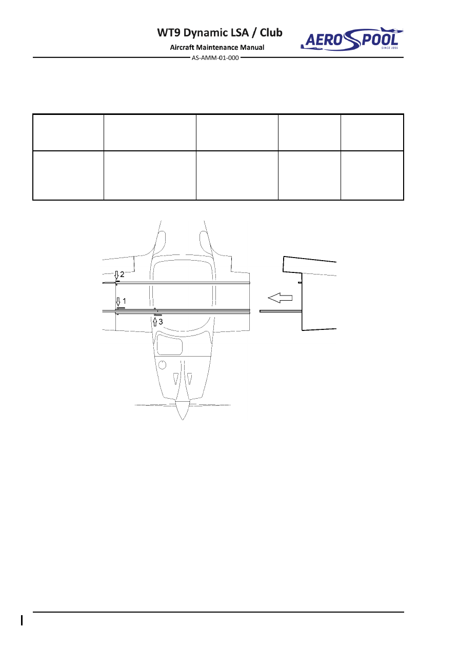
Fig.  57-1  Order of Wing Pins Removal / Installation 


OUTER WING 


WINGS 


Fig.  57-2  Wing Removal / Installation (page 1 of 2) 


Effectivity:

 ALL 

04. 07. 2019


WINGS 


  Wing 

10 

  Central section flap hinge 

  Inside main pin 

11 

  Pin 

ø

6 x 21.5 

  Outside main pin 

12 

  Split pin 

ø

1.6 x 25 

  Auxiliary pin 

13 

  Push rod 

  Safety pin 

14 

  Flap lever 

  Bolt M6 x 25 

15 

  Self-locking nut M6 

  Castle nut M6 

16 

  Washer 

ø

6.4 x 10 x 1.6 

  Washer 

ø

6.4 x 12 x 1.6 

17 

  Push-rod 2 

  Safety-pin 

ø

1.3 x 23 

18 

  Push-rod 1 

Fig.  57-2  Wing Removal / Installation (page 2 of 2) 


LEADING EDGE DEVICES 


WINGS 

57

-

40


LEADING EDGE DEVICES


1.  DESCRIPTION 

To  improve  stall  behaviour  of  an aircraft,  stall  strips  are  installed  on  outer  wing  (LH  and 
RH, marked as 200 mm stall strip (2) on Fig. 57-3) and wing central section (LH and RH, 
marked as 400 mm stall strip (1)). 

2.  MAINTENANCE PRACTICES 

A.  Stall strips 

Type of maintenance: 

Line 

Personnel qualification: 

Independent  certifying  staff  qualified  in  accordance 


with Part-66 or higher. 

Recommended tools, materials, persons and documentation: 

ITEM 

QUANTITY 

Knife 

1 pc 

Sand paper 

AR 

Araldite (2-compound epoxy adhesive) 

AR 

Persons 

Tab. 57-3 Recommended tools, materials, persons and documentation 

NOTE: 

Described is removal and installation of one of stall strip. 

(1)  Stall strips removal: 

(a)  Using hot air, heat the stall strip up to app. 60 

°

C. The resin, used to 

glue the strip to leading edge will become softer. 

CAUTION 

DO NOT OVERHEAT THE AREA UNDER AND AROUND THE 
STALL STRIP TO AVOID OF WING STRUCTURE DAMAGE. 

(b)  Using knife, carefully remove the stall strip. 

(2)  Stall strips installation: 

(a)  Mark position of stall strip on leading edge according dimensions on 

Fig. 57-4. 

(b)  Sand the leading edge area under the stall strip and degrease. 
(c)  Mask surrounding area with masking tape. 
(d)  Bond  stall  strip  to  leading  edge  using  araldite.  Remove  excessive 

glue. Let it to harden. 


Effectivity:

 ALL 

22. 05. 2017


WINGS 


  400 mm stall strip 

  200 mm stall strip 

Fig.  57-3  Stall strip position 


LEADING EDGE DEVICES 


WINGS 


  400 mm stall strip 

  200 mm stall strip 

Fig.  57-4  Stall strip position 


WING FLAPS 


WINGS 

57

-

50


WING FLAPS


3.  DESCRIPTION 

Installed  are  slotted  wing  flaps  that  are  glass/carbon  composite  sandwich 
construction. Wing flap consists of upper and lower skin, ribs and a web. Each wing 
flap is attached to the wing through three carbon hinges and one carbon/metal root 
hinge. 

4.  MAINTENANCE PRACTICES 

A.  Wing flaps 

Described is removal and installation of the left wing flap. 

Type of maintenance: 

Heavy 

Personnel qualification: 

Independent  certifying  staff  qualified  in  accordance 


with Part-66 or higher. 

Recommended tools, materials, persons and documentation: 

ITEM 

QUANTITY 

Wrench 10 

1 pc 

Wrench 9 

1 pc 

Pliers 

1 pc 

Screwdriver 

1 pc 

Serrated locking washer 

ø

6.4 

3 pcs 

Split pin 

ø

1.6 x 25 

1 pc 

Vaseline 

AR 

Loctite 243 

AR 

Persons 

Tab. 57-4 Recommended tools, materials, persons and documentation 

(1)  Wing flap removal: 

(a)  If wing is disassembled, continue with point (f). 
(b)  If wing is assembled on aircraft, set the wing flaps lever to position 3 

(flaps fully extended). 

(c)  Unscrew the nut (9, Fig. 57-5), remove washer (7). 

CAUTION 

BEFORE DISCONNECTING FLAP PUSH ROD, PROTECT 
THE UPPER SURFACE OF THE WHEEL FAIRING AS THE 
FLAP WILL FALL DOWN. 


Effectivity:

 ALL 

22. 05. 2017


WINGS 

(d)  Remove  the  split  pin  (11)  and  pull  out  the  pin  (10).  Disconnect  

the push rod (13) from the wing flap lever (12). 

(e)  Retract wing flap and fix it with adhesive tape. 
(f) 

Remove split pins (11), unscrew nuts (8), remove washers (5; 6) and 
pull out bolts (2) from three carbon hinges. 

(g)  Remove wing flap (1) from hinges. 
(h)  If necessary remove the wing flap lever (12), by unscrewing bolts (3) 

and removing washers (4; 5). 

(2)  Wing flap installation: 

(a)  Thoroughly clean and lubricate all hinges, pins and bearings with 

vaseline before each assembling (Chapter 12-20). 

(b)  If necessary install the wing flap lever (12, Fig. 57-5), using bolts (3) 

and washers (4; 5). 

(c)  Put the flap (1) in position on the aircraft; hold the flap. 
(d)  Secure flap (with adhesive tape) to prevent falling. 
(e)  Connect  flaps hinges to wing hinges using bolts (2), washers  (5;  6) 

and nuts (8); secure joints with new split pins (11). 

NOTE 

Assembled wing flaps have to move easily. Wing flap will move 
to lower position under its own weight when wing flap lever (12) 
is not connected to push rod (13). If it does not, lubricate carbon 
hinges or adjust tightness of nuts (8). 

(f) 

Check flap move to lower position due to its own weight. 

(g)  Connect  push  rod  (13)  to  the  wing  flap  lever  (12)  using  pin  (10); 

secure joint with the new split pin (11). 

(h)  Carry out test and check: 

  That castle nuts are secured with split pins. 

  If all bolt connections are tight. 

  Free plays. 

  Free movement of flaps. 

  Draining and vent holes. 

  Alignment of the trailing edges of ailerons and wing. 

  Neutral position and deflections in all flap positions. 


WING FLAPS 


WINGS 


  Wing flap 

  Castle nut M6 

  Bolt M6 x 22 

  Self-locking nut M6 

  Bolt M6 x 35 

10 

  Pin 

ø

6 x 21.5 

  Serrated locking washer 

ø

6.4 

11 

  Split pin 

ø

1.6 x 25 

  Washer 

ø

6.4 x 12 x 0.5 

12 

  Flap lever 

  Washer 

ø

6.4 x 12 x 1.6 

13 

  Push rod 

  Washer 

ø

6.4 x 10 x 1.6 


Fig.  57-5  Wing Flap Removal / Installation 


AILERONS 


WINGS 

57

-

60


AILERONS


1.  DESCRIPTION 

Ailerons are glass/carbon composite sandwich construction. Aileron consists of upper 
and  lower  skin,  ribs  and  web.  Each  aileron  is 

attached  to  the  wing’s  upper  skin 

through three carbon hinges. The aileron is fitted with a balance weight. 
The right aileron is equipped with an electrically actuated trim tab. 
Wiring  diagram  of  aileron  trim  is  described  in  the  Aircraft  Wiring  Manual 
(Doc. No. AS-AWM-01-000). 

2.  MAINTENANCE PRACTICES 

A.  Ailerons 

Type of maintenance: 

Heavy 

Personnel qualification: 

Independent  certifying  staff  qualified  in  accordance 


with Part-66 or higher. 

Recommended tools, materials, persons and documentation: 

ITEM 

QUANTITY 

Wrench 10 

1 pc 

Wrench 9 

1 pc 

Punch ø2


1 pc 

Punch ø5


1 pc 

Hammer 100 g 

1 pc 

Socket 10 

1 pc 

Pliers 

1 pc 

Screwdriver 

1 pc 

Knife 

1 pc 

Split pin 

1 pc 

Roll pin 

2 pcs 

Covering label 

1 pc 

Double side tape 12 mm 

AR 

White adhesive tape 12 mm 

AR 

Adhesive tape 

AR 

Vaseline 

AR 

Persons 

Tab. 57-5 Recommended tools, materials, persons and documentation


Effectivity:

 ALL 

12. 06. 2020


WINGS 

(1)  Aileron removal: 

(a)  Remove  transparent  cover  (9,  Chapter  06-00  Fig.  06-3) 

in  wing’s 

lower  skin  and  disconnect  push  rod  (10,  Fig.  57-6)  from  bellcrank  
(Chapter 27-10). 

(b)  Remove the Mylar tape (9), together with white tape (12) and double 

sided tape (11). 

(c)  Secure aileron (with adhesive tape) to prevent of its falling. 
(d)  Remove split pin (8), unscrew nut (7), remove washers (4; 5) and bolt 

(2) from aileron root hinge. 

(e)  Push out roll pins (6) using punch 

tool ø2 mm and push out pins (3) 

using punch tool ø5 mm from middle and tip hinge.


(f) 

Carefully remove aileron with push rod from the wing and hold it. 

(g)  In  case  of  the  right  aileron  removal,  disconnect  electrical  connector 

from the trim tab servo box. 

(h)  Disconnect push rod (10) from aileron (1) (Chapter 27-10). 
(i) 

If necessary, remove PTFE tape (13) from aileron’s upper and lower 

skin. 

(2)  Aileron installation: 

(a)  Thoroughly  clean  and  lubricate  all  hinges,  pins  and  bearings  

with vaseline before each assembling (Chapter 12-20). 

(b)  Connect push rod (10, Fig. 57-6) to the aileron (1) (Chapter 27-10). 
(c)  For right  aileron installation,  connect  electrical connector to the trim 

tab servo box. 

(d)  Put the aileron (1) in position on the aircraft; hold the aileron. 
(e)  Secure aileron (with adhesive tape) to prevent falling. 
(f) 

Insert pins (3) to the middle and tip hinges; secure them with the new 
roll pins (6). 

(g)  Connect the aileron root hinge to wing hinge using bolt (2), washers 

(4; 5) and nut (7); secure joint with the new split pin (8). 

NOTE 

The  assembled  aileron  has  to  move  easily.  The  aileron  will 
move  to  lower  position  due  to  its  own  weight  when  push  rod 

(10)  isn´t  connected  to  bellcrank.  If  it  does  not,  apply  more 

lubricant to hinges or adjust tightness of the nut (7). 

(h)  Check if aileron moves to lower position under its own weight. 
(i) 

Connect push rod (10) to the bellcrank (Chapter 27-10). 

(j) 

Check adjustment of aileron control (Chapter 27-10). 

(k) 

If necessary, stick PTFE tape (13) on aileron’s upper and lower skin.


(l) 

Remove old adhesive tapes and old glue from gap between wing and 
aileron.  Stick  double  side  tape  (11)  on  wing  surface,  install  Mylar 
tape (9) and then stick the white adhesive tape (12) on wing surface 
and Mylar tape. 


AILERONS 


WINGS 

(m)  Carry out test and check: 

  That castle nuts are secured with split pins. 

  If all bolt connections are tight. 

  Free plays. 

  Free movement of ailerons. 

  Fitting of roll pins. 

  Draining and vent holes. 

  Alignment of the trailing edges of ailerons and wing. 

  Neutral position and deflection limits. 


Fig.  57-4  Aileron Removal / Installation (page 1 of 2)  

  Aileron 


Split pin ø1.6 x 

25 

  Bolt M6 x 37 

  Mylar tape 


Pin ø6 x 30


10 

  Push rod 


Washer ø6.4 x 12 x 1.6


11 

  Double sided tape 


Washer ø6.4 x 12 x 0.5


12 

  White tape 


Roll pin ø2 x 

12 

13 

  PTFE tape 

  Castle nut M6 


Fig.  57-6  Aileron Removal / Installation (page 2 of 2)


Effectivity:

 ALL 

04. 07. 2019


WINGS 

B.  Aileron trim tab actuator 

Type of maintenance: 

Heavy 

Personnel qualification: 

Independent  certifying  staff  qualified  in  accordance 
with Part-66 or higher. 

Recommended tools, materials, persons and documentation: 

ITEM 

QUANTITY 

Philips screwdriver 

1 pc 

Wrench 10 

2 pcs 

Pliers 

1 pc 

Socket 5.5 

1 pc 

Cotter pin 

1 pc 

Protractor with deflecting pointer 

1 pc 

Persons 

Tab. 27-6 Recommended tools, materials, persons and documentation 

(1)  Aileron trim tab actuator removal: 

(a)  Open the 

ROLL

 circuit-breaker. 

(b)  Remove the right aileron (see 2.A.(1)). 
(c)  Unscrew nuts (7, Fig. 57-7), remove washers (8), bolts (9) and cover 

(10). 

(d)  Remove the cotter pin (6), washer (5), pin (4) and disconnect the rod 

(3) from the trim tab lever (12). 

(e)  Disconnect the electrical connector (2) from the connector (13). 
(f) 

Unscrew  nuts  (7),  remove  washers  (8)  and  carefully  remove  
the actuator (1) from the box. 

(g)  As  necessary,  remove  the  cotter  pin  (6),  washer  (5),  pin  (4)  

and disconnect the rod (3) from the actuator (1). 

(2)  Aileron trim tab actuator installation: 

(a)  If  necessary,  fit  the  rod  (3,  Fig.  57-7)  to  the  actuator,  insert  pin  (4) 

into the hole, insert the washer (5) and secure with the new cotter pin 
(6). 

(b)  Insert the trim tab actuator (1) into the box and fit it in place. 
(c)  Put  nuts  (7)  with  washers  (8)  on  the  bolts  in  the  box  and  carefully 

tighten nuts (7). 

(d)  Fit  the  rod  (3)  to  the  control  lever  (12),  insert  pin  (4)  into  the  hole, 

insert the washer (5) and secure it with the new cotter pin (6). 

(e)  Connect the electrical connector (2) to the connector (13). 


AILERONS 


WINGS 

(f) 

Fit the cover (10) to the box, insert bolts (9) from top side, washers 
(8) and nuts (7) from bottom side. Tighten nuts. 

(g)  Install the right aileron (see 2.A.(2)) 
(h)  Close the ROLL circuit-breaker. 
(i) 

Carry out test and check: 

  If all bolt connections are tight. 

  That all lock nuts are tight. 

  Free movement of aileron control system. 

  Alignment of the trailing edges of ailerons and wing. 

  Neutral position and max. deflections. 

  Equal division of the threads on the push rods. 

  That no foreign objects remained in the aircraft. 

(3)  Adjustment / test 

 aileron trim tab deflections: 

CONTROL SURFACE DEFLECTIONS 

Control surface 

Up 

Down 

Distance measurement point 

from the point of rotation 

Trim tab 

18 ±1°


20 ±1°


Tab.  27-7  Trim Tab Deflections 

(a)  Set the aileron to neutral position. 
(b)  Put protractor on trailing edge of aileron trim tab root. 
(c)  Set the aileron trim tab to neutral position. 
(d) 

Set the protractor to 0°

- starting value for measuring. 

(e)  Deflect  trim  tab  to  the  max.  up  and  max.  down  possible  position  

and read the deflection value. 

(f) 

Check deflection values in accordance with Tab. 27-7. 

(g)  If  deflections  are  not  within  range  listed  in  Tab.  27-7,  adjust  forks  

on the push pull rod (3, Fig. 57-7). 

(h)  Carry out test and check: 

  Deflections of aileron trim tab. 

  Rod ends are in safety. 

  That no foreign objects remain in the aircraft. 


Effectivity:

 ALL 

04. 07. 2019


WINGS 


  Actuator 

   Washer 3.2 x 7 x 0.5 

  Electrical connector 

  Bolt M3 x 12 

  Push-pull rod 

10 

  Cover 

  Pin 

11 

  Right aileron 

  Washer 

12 

  Trim tab lever 

  Cotter pin 

13 

  Electrical connector 

  Nut M3 


Fig.  57-7  Aileron Trim Actuator Removal / Installation 


AILERONS 


WINGS 

C.  Aileron trim tab: 

Type of maintenance: 

Heavy 

Personnel qualification: 

Independent  certifying  staff  qualified  in  accordance 


with Part-66 or higher. 

Recommended tools, materials, persons and documentation: 

ITEM 

QUANTITY 

Hammer 100 g 

1 pc 

Pliers 

1 pc 

Locking wire ø 0

.8 mm 

AR 

Vaseline 

AR 

Persons 

Tab. 57-8 Recommended tools, materials, persons and documentation 

(1)  Aileron trim tab removal: 

(a)  Remove the right aileron (see 2.A.(1)). 
(b)  Disconnect servo and push rod from the trim tab lever (3, Fig. 57-7). 
(c)  Cut the locking wire which is securing hinge rod (2, Fig. 57-8). 
(d)  Hold the trim tab and remove the hinge rod (2). 
(e)  Remove the trim tab (1). 

(2)  Aileron trim tab installation 

(a)  Thoroughly  clean  and  inspect  hinges,  lubricate  the  hinge  rod  

with vaseline (Chapter 12-20). 

(b)  Align trim tab hinges with hinges on the aileron. 
(c)  Carefully insert the hinge rod (2, Fig. 57-8). 
(d)  Secure  end  of  the  rod  (2)  to  the  bracket  (4)  with  locking  wire  (3) 

(Chapter 20-20). 

(e)  Connect servo push rod to the trim tab lever (3, Fig. 57-7). 
(f) 

Install the right aileron (see 2.A.(2)). 


Content      ..     35      36      37      38     ..