WT9 Dynamic LSA. AIRCRAFT MAINTENANCE MANUAL (AS-AMM-01-000, 22. 05. 2017) - page 41
 

  Index      Manuals     WT9 Dynamic LSA. AIRCRAFT MAINTENANCE MANUAL (AS-AMM-01-000, 22. 05. 2017)


Search            copyright infringement  


Content      ..     39      40      41      42     ..


WT9 Dynamic LSA. AIRCRAFT MAINTENANCE MANUAL (AS-AMM-01-000, 22. 05. 2017) - page 41


AIR INTAKES 


POWER PLANT 

- GENERAL 


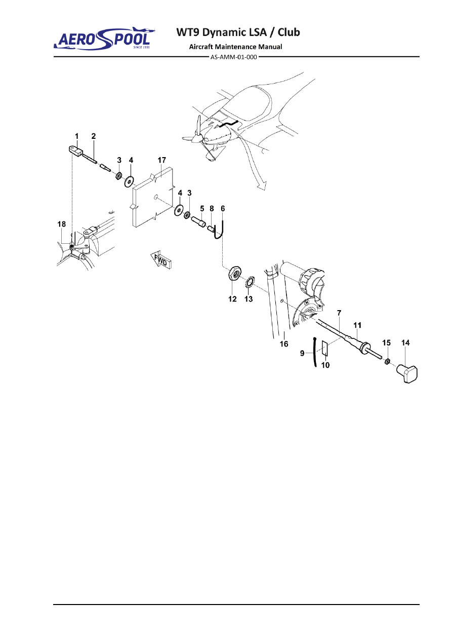
  Cable end fitting 

11 

  Green sleeve 

  Thread rod 

12 

  Low nut M10 

  Low nut M6 

13 

  Serrated locking washer 

ø

10.5 

  Washer 

ø

6.4x 18 x 1.2 

14 

  Handle 

  Screw shackle 

15 

  Low nut M5 

  Lockwire 

ø

 0.8 

For information: 

  Control cable 

16 

  Central console 

  Bowden end 

17 

  Firewall 

  Cable tie 2.6 

18 -  Air filter holder bellcrank 

10 

  Textile adhesive tape 


Fig.  71-12  Carburettor Pre-Heat Control Removal / Installation 


Effectivity:

 ALL 

28. 04. 2021


POWER PLANT 
- GENERAL 


D.  Airbox pre-heat exchanger 

For removal / installation, see the Chapter 78-10. 


ENGINE DRAINS 


POWER PLANT 

- GENERAL 

71-70


ENGINE DRAINS


1.  DESCRIPTION 

The  engine  installed  in  the  aircraft  has  the  following  engine  drains  and  venting  
(see Fig. 71-13): 

  Airbox drain. 

  Drip tray drain. 

  Fuel drain from the fuel pump. 

  Oil tank venting (Chapter 79). 

  Carburettors float chamber venting. 

All drains consist of the rubber hoses. Hoses from each drip tray and airbox connect 
to a Y piece connector. From the Y piece connector, the drain hose leads to the bottom 
of the firewall. All hoses discharges bellow the fuselage into the slipstream. 


  C

arburettor’s

 float chamber venting  4 

  Drip tray drain 

  Airbox drain 

  Fuel pump drain 

  Drip tray 

  Oil tank venting 

Fig.  71-13  Engine Drains 


Effectivity:

 ALL 

28. 04. 2021


POWER PLANT 
- GENERAL 


2.  MAINTENANCE PRACTICES 

A.  Drains 

Type of maintenance: 

Line 

Personnel qualification: 

Independent  certifying  staff  qualified  in  accordance 


with Part-66 or higher. 

Recommended tools, materials, persons and documentation: 

ITEM 

QUANTITY 

Screwdriver 2 

1 pc 

Wire nippers 

1 pc 

Cable tie 2.6 

AR 

Cable tie 4.8 

AR 

Persons 

Tab. 71-7 Recommended tools, materials, persons and documentation 

WARNING 

ENGINE  IGNITION  MUST  BE  SWITCHED  OFF.  DISCONNECT 
NEGATIVE TERMINAL OF AIRCRAFT BATTERY. 

(1)  Drains removal: 

(a)  Make sure that the 

IGNITION 

switches are set to 

OFF

(b)  Remove the engine cowlings (Chapter 71-10). 
(c)  Disconnect negative terminal of battery (Chapter 24-30). 
(d)  Remove  all  cable  ties  (10,  Fig.  71-14)  on  length  of  drain  hoses  

(1; 2; 3; 4; 5; 6) and safety clamps (8; 9). 

(e)  Disconnect and remove drain hoses. 

(2)  Drains installation: 

(a)  Make sure that the 

IGNITION 

switches are set to 

OFF

(b)  Route the drain hoses (1; 2; 3; 4; 5; 6, Fig. 71-14). 
(c)  Connect  drain  hoses  with  3-way  distributors  (7)  and  secure  drain 

hoses with cable ties (10) and safety clamps (8; 9). 

(d)  Secure drain hoses (3, 4) with necessary amount of cable ties. 
(e)  Check if all hoses are well secured. 
(f) 

Install the engine cowlings (Chapter 71-10). 


ENGINE DRAINS 


POWER PLANT 

- GENERAL 


  Draining hose 

  N/A 

  Draining hose 

  Safety clamp 10.9 

  Draining hose 

10 

  Cable tie 2.6 

  Draining hose 

11 

  Holder 

  Draining hose 

12 

  Bolt 

ø

3x10 

  Draining hose 

13 

  Hose clamp 

ø20

 - 32 

  3-way distributor 

14 

  Cable tie 4.8 

Fig.  71-14  Engine Drains 


GENERAL 


ENGINE -  

FUEL AND CONTROL 

73-00  GENERAL 

1.  INTRODUCTION 

This  chapter  describes  those  units  and  components  which  deliver  metered  fuel  
to the engine. Components covered the standby fuel pressure indicator, fuel pressure 
sensor and fuel flow transducer that part of aircraft manufacturer installation. 

Fuel  is  supplied  to  the  engine  in  dependence  from 

FUEL

  selector  valve  position 

(

LEFT

  - 

RIGHT

  - 

OFF

).  From  both  fuel  tanks  the  fuel  flows  through  the  fuel  filters  

to  the 

FUEL

  selector  valve  inlets.  From  the 

FUEL

  selector  valve  the  fuel  flows 

through  the  electric  fuel  pump  (by-passed  with  check  valve)  to  engine  driven  fuel 
pump and then to distributor inlet. 

One  of  distributor's  outlets  is  connected  to  carburettors  through  the  fuel  flow  meter 
sensor  and  3-way  distributor.  Second  one  is  fitted  with  restrictor  jet  to  which  return 
line is connected. Return line leads back to the left fuel tank. 

Fuel  flow  transducer  is  installed  the  way  to  measure  only  the  fuel  consumed  
by engine. For installation of fuel flow transducer see Chapter 28-40. 

Fuel  pressure  sensor  and  standby  fuel  pressure  indicator  are  installed  in  the  fuel 
system and  connected  through  the  3-way  distributor  with  restrictor  jets  in  its  outlets  
to  the  4-way  distributor.  Both  check  the  actual  pressure  in  the  fuel  supply  line.  
For  installation  of  fuel  pressure  sensor  see  Chapter  28-40.  For  installation  of  fuel 
pressure indicator see Chapter 39-10. 

Scheme of fuel system is stated in Chapter 28. 

Wiring  diagram  of  fuel  pressure  sensor  and  fuel  flow  transducer  is  described  
in the Aircraft Wiring Manual (Doc. No. AS-AWM-01-000). 


Effectivity:

 ALL 

12. 06. 2020


ENGINE -  
FUEL AND CONTROL 


2.  TROUBLESHOOTING 


TROUBLE 

POSSIBLE CAUSE 

REMEDY 

Insufficient fuel pressure. 

Clogged strainer. 

Clean strainer. 

Defective mechanical fuel 
pump. 

Replace fuel pump. 

Defective fuel pressure 
sensor. 

Replace the fuel pressure 
sensor. 

Wrong fuel pressure 
sensor set up in Dynon 
Skyview. 

Set up correctly fuel 
pressure sensor in Dynon 
SkyView. 

Defective fuel pressure 
indicator. 

Replace the fuel pressure 
indicator. 

No fuel pressure 
indication 

Defective fuel pressure 
sensor. 

Replace the fuel pressure 
sensor. 

Faulty or incorrect fuel 
pressure sensor wiring. 

Repair/Replace wire(s). 

Fluctuating fuel flow 
indications. 

Defective fuel flow 
indicator/transducer. 

Replace fuel flow 
indicator/transducer 

Vapor in fuel lines. 

Turn on electric fuel 
pump. 


GENERAL 


IGNITION 

74-00  GENERAL 

1.  INTRODUCTION 

This chapter describes those units and components which furnish, distribute, and 
control an electrical current to ignite the fuel-air mixture in the engine cylinders. The 
ignition components include coils, electronic modules, ignition harness, spark plugs, 
and ignition switches. 

Wiring diagram of sensor ignition is described in the Aircraft Wiring Manual 
(Doc. No. AS-AWM-01-000). 


Effectivity:

 ALL 

22. 05. 2017


IGNITION 


2.  TROUBLESHOOTING 


TROUBLE 

POSSIBLE CAUSE 

REMEDY 

Engine does not start/not 
easy to start. 

Ignition switch/switch 
cable defective. 

Carry out the ignition 
switch test. 
If necessary replace the 
ignition switch or ignition 
switch cables. 

Defective ignition spark-
plug leads. 

Replace the spark-plug 
leads. 

Low battery voltage. 

Charge / replace battery. 

Fouled spark plugs. 

Clean spark plugs 
according to 
manufacturer’s 
specifications. 

Incorrect spark plug gap. 

Re-gap spark plugs to 
engine manufacturer’s 
specifications. 

Rough running. 

Fouled spark plugs. 

Clean spark plugs 
according to 
manufacturer’s 
specifications. 

Incorrect spark plug gap. 

Re-gap spark plugs to 
engine manufacturer’s 
specifications. 

Ignition switch/switch 
cable defective. 

Carry out the ignition 
switch test. 
If necessary replace the 
ignition switch or ignition 
switch cables. 

Excessive RPM drop 
during ignition test. 

Fouled spark plugs. 

Clean spark plugs 
according to 
manufacturer’s 
specifications. 

Incorrect spark plug gap. 

Re-gap spark plugs to 
engine manufacturer’s 
specifications. 

Faulty spark plug.  

Test spark plug in 
accordance with 
manufacture’s 
specifications. 


ELECTRICAL POWER SUPPLY 


IGNITION 

74-10  ELECTRICAL POWER SUPPLY 

1.  DESCRIPTION 

The engine Rotax 912 ULS2 engine is equipped with a dual ignition unit of a 
breakerless, capacitor discharge design, with an integrated generator  
(Chapter 24-10). 

The ignition unit needs no external power supply. 

Two independent charging coils (1) located on the generator stator supply one 
ignition circuit each. The energy is stored in capacitors of the electronic modules  
(2, Fig. 74-1). At the moment of ignition 2 each of the 4 external trigger coils (3) 
actuate the discharge of the capacitors via the primary circuit of the ignition coils (4). 
The trigger coil (5) is provided for rpm indicator signal (Chapter 39-10). 


–  Charging coils 

–  Dual ignition coils 

–  Electronic modules 

–  Trigger coils for speed signal 

–  Trigger coils for ignition signal 


Fig.  74-1  Ignition System 


Effectivity:

 ALL 

22. 05. 2017


IGNITION 


Firing order: 1-4-2-3 (see Fig. 74-2). 


Fig.  74-2  Firing Order 


2.  MAINTENANCE PRACTICES 

Refer to the Maintenance Manual for Engine Type 912 Series, Ref. No.: MML-912 for 
maintenance practices information. 


DISTRIBUTION 


IGNITION 

74-20  DISTRIBUTION 

1.  DESCRIPTION 

This chapter describes that portion of the ignition system which conducts high-
voltage electricity from the electronic modules to the spark plugs. Shielded leads 
connect the electronic modules to the spark plugs. 

Two spark plugs in each cylinder give ignition to the engine. Ignition circuit A controls 
top spark plugs of cylinder 1 and 2; lower spark plugs of cylinder 3 and 4. Ignition 
circuit B controls top spark plugs of cylinder 3 and 4; lower spark plugs of cylinder 1 
and 2. 

2.  MAINTENANCE PRACTICES 

Refer to the Maintenance Manual for Engine Type 912 Series, Ref. No.: MML-912 for 
maintenance practices information. 


SWITCHING 


IGNITION 

74-30  SWITCHING 

1.  DESCRIPTION 

Ignition circuits are controlled independently by switches on the instrument panel 
labelled 

IGNITION

. The left switch controls the ignition circuit A; the right switch 

controls the ignition circuit B. Starter is controlled by a keyed ignition switch installed 
in the instrument panel. Keyed ignition switch is labeled clockwise: 


OFF  

Off-state. 


INST. 

Instrument connection. 


CHARGE 

Charging. 


START 

The starter is energized and will crank the engine, when the key is  


released, it will automatically return to the 

CHARGE

 position. 

Activation of the ignition circuit A and ignition circuit B is signalized on the SV-D1000 
EMS screen (Chapter 77-00). 


–  Left ignition circuit switch 

–  Keyed ignition switch 

–  Right ignition circuit switch 


Fig.  74-3  Ignition Controls 


Effectivity:

 ALL 

22. 05. 2017


IGNITION 


2.  MAINTENANCE PRACTICES 

A. 

Ignition switches 

For removal / installation procedures refer to Chapter 39-10. 

B. 

Keyed ignition switch 

For removal / installation procedures refer to Chapter 39-10. 


Content      ..     39      40      41      42     ..