WT9 Dynamic LSA. AIRCRAFT MAINTENANCE MANUAL (AS-AMM-01-000, 22. 05. 2017) - page 14
 

  Index      Manuals     WT9 Dynamic LSA. AIRCRAFT MAINTENANCE MANUAL (AS-AMM-01-000, 22. 05. 2017)


Search            copyright infringement  


Content      ..     12      13      14      15     ..


WT9 Dynamic LSA. AIRCRAFT MAINTENANCE MANUAL (AS-AMM-01-000, 22. 05. 2017) - page 14


Effectivity:

 ALL 

04. 07. 2019


ELECTRICAL 
POWER 


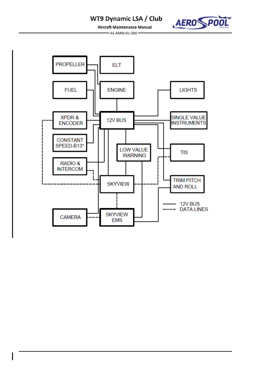
Fig.  24-2 


Simplified Schematic Diagram (Towing Version) 


DC GENERATION 


ELECTRICAL 

POWER 

24-30  DC GENERATION 

1.  DESCRIPTION 

A. 

Generator system 

The generator system consists of the following components: 

  Generator 

  Voltage regulator 

  Charging fuse 

  Low voltage warning light 

The maintenance free  AC  generator  is integrated into the engine and supplies 
power to the equipment during normal operation. 

The  generated  AC  voltage  is  rectified  and  regulated  by  the  voltage  regulator.  
The voltage regulator and charging fuse are installed on the firewall in the engine 
compartment. 

The low voltage  warning  light 

CHARGE

 is located on the left  instrument panel 

(Chapter 39-10). 

B. 

Battery 

The lead acid maintenance free battery 12 V / 17 Ah or 12V / 20 Ah battery is 
installed in the engine compartment at the firewall; supplies power to the starter 
and is also used as an emergency power supply when the engine has stopped. 

C. 

SV-BAT-320 backup battery 

SkyView displays have the SV-BAT-320 external backup batteries. In the event 
of  an  electrical  failure  that  causes  SkyView  to  run  on  the  SV-BAT-320, 
the SV-BAT-320 supplies power to the SkyView display it is connected to, along 
with any connected SV-ADAHRS-200, SV-EMS-220, and SV-GPS-250 module. 
A  fully  charged  SV-BAT-320  can  keep  most  SkyView  systems  operating  
for at least 45 minutes. 

NOTE 

Refer  to  “Dynon  Avionics  SkyView  System  Installation,  Document 
101320-

022, Revision Q” or later for additional information.


Effectivity:

 ALL 

04. 07. 2019


ELECTRICAL 
POWER 


2.  MAINTENANCE PRACTICES 

A. 

Generator 

Refer  to  the  Maintenance  Manual  for  Engine  Type  912  Series,  Ref.  No.:  
MML-912 for maintenance practices information. 

B. 

Voltage regulator 

Type of maintenance: 

Line 

Personnel qualification: 

Independent  certifying  staff  qualified  in  accordance  


with Part-66 or higher. 

Recommended tools, materials, persons and documentation: 

ITEM 

QUANTITY 

Wrench 13 

2 pcs 

Persons 

Tab. 24-1 Recommended tools, materials, persons and documentation 

WARNING 

ENGINE  IGNITION  MUST  BE  SWITCHED  OFF.  DISCONNECT 
NEGATIVE TERMINAL OF AIRCRAFT BATTERY. 

(1)  Voltage regulator removal: 

(a)  Make sure that the 

IGNITION

 switches are set to 

OFF

(b)  Remove the engine cowlings (Chapter 71-10). 

(c)  Disconnect the battery. 

(d)  Disconnect the connector (7, Fig. 24-3) from the regulator (1).  

(e)  Remove  the  mounting  nuts  (3),  washers  (4,  5),  ground  wire  (6)  and 

bolts (2). 

(f) 

Remove the regulator (1). 

(2)  Voltage regulator installation 

(a)  Make sure that the 

IGNITION

 switches are set to 

OFF

(b)  Put the regulator (1, Fig. 24-3) in position on the firewall (8).  

(c)  Hold the regulator and attach it with bolts (2), washers (4, 5), ground 

wire (6) and nuts (3). 

(d)  Connect the connector (7) to the regulator (1). 

(e)  Check if regulator is firmly secured. 

(f) 

Connect the battery. 

(g)  Install the engine cowlings (Chapter 71-10). 

(h)  Carry out an operational test; check function.


DC GENERATION 


ELECTRICAL 

POWER 


– Voltage regulator 

– Washer Ø6.4 x 12 x 1.6 

– Bolt M6 x 25 

– Ground wire 

– Self-locking nut M6 

7 - Connector 

– Washer 

Ø

6.4 x 18 x 1.6 

– Firewall 

Fig.  24-3  Voltage Regulator Removal / Installation 


Effectivity:

 ALL 

04. 07. 2019


ELECTRICAL 
POWER 


C. 

Battery 

Type of maintenance: 

Line 

Personnel qualification: 

Independent  certifying  staff  qualified  in  accordance  


with Part-66 or higher. 

Recommended tools, materials, persons and documentation: 

ITEM 

QUANTITY 

Wrench 7 

1 pc 

Wrench 8 

1 pc 

Persons 

Tab. 24-2 Recommended tools, materials, persons and documentation 

(1)  Battery removal: 

(a)  Remove the engine cowlings (Chapter 71-10). 

(b)  Unscrew the bolt (6, Fig. 24-4), remove washers (8; 9) and cover (3). 

(c)  First disconnect wires (12) from negative terminal (13), by unscrewing 

the nut (11), removing the washers (7) and the bolt (4). 

(d)  Perform same procedure with wires (15) on positive terminal (14). 

(e)  Unscrew the nut (11) and remove the washers (7; 10) and the bolt (5), 

open holder (16) and remove the battery (1). 

(f) 

Pull out the battery from Econet casing (2). 

(2)  Battery installation: 

(a)  Put the battery (1, Fig. 24-4) to the Econet casing (2).  

(b)  Open holder (16), insert battery (1) and attach it by means of the bolt 

(5), washers (7; 10) and nut (11). 

(c)  First connect wires (15) with positive terminal (14) by means of the bolt 

(4), washers (7) and nut (11). 

(d)  Perform same procedure with wires (12) on negative terminal (13). 

(e)  Install  cover  (3)  and  attach  it  by  means  of  the  bolt  (6)  and  washers  

(8; 9). 

(f) 

Install the engine cowlings (Chapter 71-10). 


DC GENERATION 


ELECTRICAL 

POWER 


Fig.  24-4  Battery Removal / Installation (page 1 of 2) 


Effectivity:

 ALL 

04. 07. 2019


ELECTRICAL 
POWER 


–  Battery 

10 

–  Washer 

Ø

6.4 x 20 x 6 

–  Econet casing 

11 

–  Self-locking nut M5 

–  Cover 

12 

–  Wires (-) 

–  Bolt M5x15 

13 

–  Negative terminal 

–  Bolt M5x18 

14 

–  Positive terminal 

–  Bolt M4x10 

15 

–  Wires (+) 

–  Washer 

Ø

5.3 x 15 x 1.2 

For information: 

–  Washer 

Ø

4.3 x 12 x 1 

16 

–  Battery holder 

–  Spring locking washer 

Ø

4.3 


Fig.  24-4  Battery Removal / Installation (page 2 of 2)  

D. 

SV-BAT-320 backup battery 

Type of maintenance: 

Line 

Personnel qualification: 

Independent  certifying  staff  qualified  in  accordance  


with Part-66 or higher. 

Recommended tools, materials, persons and documentation: 

ITEM 

QUANTITY 

Wrench 7 

1 pc 

Screwdriver 

1 pc 

Philips screwdriver 

1 pc 

Persons 

Tab. 24-3 Recommended tools, materials, persons and documentation 

NOTE 

Described  is  procedure  for  removal/installation  of  backup  battery  
on  the  left  instrument  floor.  The  procedure  for  backup  battery  
on the right instrument floor is analogous. 

(1)  Backup battery removal: 

(a)  Remove the instrument panel cover (Chapter 39-10). 

(b)  Disconnect the connector (3, Fig. 24-5) from the backup battery (1; 2).  

(c)  Remove the mounting nuts (5), washers (6) and bolts (4). 

(d)  Remove the backup battery (1; 2) from the instrument floor (7, 8). 

(2)  Backup battery installation: 

(a)  Put the backup battery (1; 2, Fig. 24-5) in position on the instrument 

floor (7; 8). 

(b)  Hold the battery and attach it with bolts (4), washers (6) and nuts (5). 

(c)  Connect the connector (3) to the backup battery (1, 2). 

(d)  Install the instrument panel cover (Chapter 39-10). 

(e)  Carry  out  an  operational  test  (see  Dynon  Avionics  SkyView  System 

Installation, Document 101320-

022, Revision Q” or later).


DC GENERATION 


ELECTRICAL 

POWER 


– Left backup battery 

– Washer 

Ø

4.3 x 12 x 1 

– Right backup battery 

For information: 

– Connector 

– Left instrument floor 

– Bolt M4 x 12 

– Right instrument floor 

– Self-locking nut M4 


Fig.  24-5   SV-BAT-320 Backup Battery Removal / Installation 


Effectivity:

 ALL 

22. 05. 2017


ELECTRICAL 
POWER 


This page is left blank intentionally 


EXTERNAL POWER 


ELECTRICAL 

POWER 

24-40  EXTERNAL POWER 

1.  DESCRIPTION 

The  aircraft  is  equipped  with  the  external  power  source  socket,  which  is  located  
in  the  left  side  of  the  cabin,  bellow  the  instrument  panel.  External  power  source  
is  intended  for  engine  starting,  maintenance  procedures  requiring  reliable  power  
for an extended period and for battery charging. 

Recommended power source output is: 

Shortly for engine start: 


Max. 12 V / 90 A DC 

For maintenance purposes:  

Max. 12 V / 25 A DC 

2.  MAINTENANCE PRACTICES 

A. 

External power socket 

Type of maintenance: 

Line 

Personnel qualification: 

Independent  certifying  staff  qualified  in  accordance  


with Part-66 or higher. 

Recommended tools, materials, persons and documentation: 

ITEM 

QUANTITY 

Pads (various thickness) 

AR 

Spirit level 

1 pc 

Persons 

Tab. 24-4 Recommended tools, materials, persons and documentation 

(1)  External power socket removal: 

(a)  Remove the engine cowlings (Chapter 71-10). 

(b)  Disconnect the battery and cables (5, Fig. 24-6). 

(c)  Pull out the cables (5) through the firewall from engine compartment. 

(d)  Unscrew  the  nuts  (3),  remove  washers  (4),  bolts  (2)  and  remove  

the external power socket (1) with cables (5). 

(2)  External power socket installation: 

(a)  Put the external power socket (1, Fig. 24-6) in position on the bracket 

(6). 

(b)  Attach the socket (1) with bolts (2), washers (4), and nuts (3). 

(c)  Pull the cables (5) through the firewall to engine compartment. 

(d)  Connect the cables (5) and battery. 

(e)  Install the engine cowlings (Chapter 71-10). 

(f) 

Carry out an operational test; check function. 


Effectivity:

 ALL 

04. 07. 2019


ELECTRICAL 
POWER 


–  External power socket 

–  Cable 

–  Bolt M5 x 18 

For information: 

–  Self-locking nut M5 

–  Bracket 

–  Washer 

Ø

5.3 x 15 x 1.2 


Fig.  24-6  External Power Socket Removal / Installation 


DC ELECTRICAL LOAD DISTRIBUTION  


ELECTRICAL 

POWER 

24-60  DC ELECTRICAL LOAD DISTRIBUTION 

1.  DESCRIPTION 

The  electrical  power  from  the  generator  and  the  battery  is  supplied  via  12  V  bus, 
switches and circuit breakers to the individual electrical equipment. 
Switches are installed at the lower edge of instrument panel’s left side. 
Circuit breakers are located at the lower and right side of instrument panel’s right side. 
Circuit breaker

’s marking and values are listed in the Table 24-5. 

Dual  contactless  ignition  of  the  engine  it  is  a  separate  part  of  electrical  installation. 
Each ignition circuit can be switched off independently using corresponding 

IGNITION


switch 

(see 

Chapter 

74-30). 

Keyed 

ignition 

switch 

is 

connected  

to the battery through a 

MASTER SWITCH

. It has positions 

OFF 

INST. 

CHARGE 

START

. In the 

OFF 

position, the starter is electrically isolated. In the 

INST. 

position 

are energized single value instruments (engine hours and flight hours) and fuel pump. 
In  the 

CHARGE 

position  also  a  warning  lamp 

CHARGE 

is  energized  and  indicates  

the  charging  status.  In  the 

START 

position,  the  starter  is  energized  and  will 

automatically return to the position 

CHARGE 

when released. 

PFD and MFD displays Dynon SkyView SV-D1000 are connected through 

LH D1000


and 

LH D1000 

circuit breakers directly to the 

MASTER SWITCH

Avionics (RDST, XPDR, intercom and traffic sensor) are connected through separate 

COMM

,

 NAV

,

 XPDR,


INTERCOM

 and 

TIS

 circuit breakers to the avionic relay. Avionic 

relay is activated by separate 

AVIONICS

 switch and is protected by 

AVIONICS

 circuit 

breaker that is connected to the 

MASTER SWITCH

Navigation  and  anti-collision  lights  are  activated  by

  NAV  /  ACL

  switch  and  are 

connected through 

NAV / ACL

 circuit breaker to the 

MASTER SWITCH

. Landing lights 

are  activated  by 

LAND

  switch  and  are  connected  through 

LAND

  circuit  breaker  

to the 

MASTER SWITCH

Fuel  pump  is  activated  by  separate 

FUEL  PUMP

  switch  and  is  connected  through  

FUEL PUMP

 circuit breaker to the 

INST.

 position of keyed ignition switch. 

Stall warning system consists of  stick shaker handle, buzzer and warning lamp that 
are  triggered  by ACI Stall  Warner  (AoA flap)  and  Stall  Warning  Transducer  (buzzer 
and  warning  lamp  only).  Stall  warning  system  is  connected  through 

STALL 

circuit 

breaker to the 

MASTER SWITCH

Function of warning lamps, control lamps, stick shaker and stall warning horn can be 
verified by pressing button labelled 

TEST

Pitch  and  roll  trim  actuators  are  activated  by  separate  switches  and  are  connected 
through 

PITCH

 and

 ROLL

 circuit breakers to the 

MASTER SWITCH

Low oil pressure warning circuit and low fuel level warning circuit have a separate 

OIL 

PRESS.

 and 

FUEL RES.

 circuit breakers. 

12 V sockets of an automotive type are installed at the both lower corners of instrument 
panel and are connected through 

SOC. 12V

 circuit breaker to the 

MASTER SWITCH

Engine hours and flight hours are supplied through 

SVI

 circuit breaker from the 

INST.


position of keyed ignition switch. 

ELT has its own battery for power supply.


Effectivity:

 ALL 

28. 04. 2021


ELECTRICAL 
POWER 


Towing version: 

Camera is activated by

 CAMERA

 switch and is connected through 

CAMERA

 circuit 

breaker to the 

MASTER SWITCH

Propeller is regulated by a propeller regulator and is connected through 

PROPELLER


circuit breaker to the 

MASTER SWITCH

NO.  MARKING 

PROTECTED INSTRUMENT 

VALUE (A) 

1. 

PITCH* 

Pitch trim actuator 

7.5 

2. 

ROLL* 

Roll trim actuator 

3. 

STALL* 

Stall warning system 

4. 

AVIONICS 

Avionics relay 

5. 

FUEL PUMP 

Fuel pump 

6. 

COMM 

GNC 255A (COMM) 

10 

7. 

XPDR 

GTX 328 

GTX 335 

8. 

LH D1000 

LH Dynon SkyView SV-D1000 

9. 

RH D1000 

RH Dynon SkyView SV-D1000 

10. 

OIL PRESS. 

Low oil pressure warning 

11. 

FUEL RES. 

Low fuel level warning 

12. 

SOC. 12V 

LH and RH socket 12V 

10 

13. 

SVI 

Engine hours counter Hobbs 
Flight hours counter Winter FSMZ 
RPM indicator ROAD IF61.2B35.2301 

14. 

TIS 

TRX-1500 

AT-1 

15. 

SPARE 

16. 

NAV / ACL 

Anti-collision lights 

17. 

LAND 

Landing lights 

18. 

NAV 

GNC 255A (NAV) 

19. 

INTERCOM 

PM3000 

20. 

CAMERA 

Camera (towing version) 

21. 

PROPELLER* 

Propeller regulator (towing version) 

Tab. 24-5 Circuit breakers rating 

NOTE 

*KLIXON  7277-2  circuit  breakers  are  used  in  pitch  trim,  roll  trim,  stall 
warning  system  and  propeller  circuits.  Remaining  circuits  are  protected  
by ETA 106-P10 circuit breakers.


DC ELECTRICAL LOAD DISTRIBUTION  


ELECTRICAL 

POWER 

2.  MAINTENANCE PRACTICES 

A. 

12 V socket 

For removal / installation, see the Chapter 39-10. 

B. 

ETA 106-P10 circuit breakers 

For removal / installation, see the Chapter 39-10. 

C. 

KLIXON 7277-2 circuit breakers 

For removal / installation, see the Chapter 39-10. 

D. 

Switches 

For removal / installation, see the Chapter 39-10. 

E. 

Propeller regulator 

For removal / installation, see the Chapter 39-10. 

F. 

Trim switches 

Type of maintenance: 

Line 

Personnel qualification: 

Independent  certifying  staff  qualified  in  accordance 
with Part-66 or higher. 

Recommended tools, materials, persons and documentation: 

ITEM 

QUANTITY 

Pliers 

1 pc 

Persons 

Tab. 24-10 Recommended tools, materials, persons and documentation 

NOTE 

Removal / installation is same for both switches. 

(1)  Trim switch removal: 

(a)  Remove the engine cowlings (Chapter 71-10). 

(b)  Set the 

MASTER SWITCH

 to 

OFF

 position. 

(c)  Remove  the  pedestal  panel  (Chapter  27-50)  to  gain  access  

to the underside of the switch. 

(d)  Disconnect all wires (2, Fig. 24-7) from the switch. 

(e)  Compress the retainers on the switch (1) and push up to remove. 

(2)  Trim switch installation: 

(a)  Compress  the  retainers  on  the  switch  (1,  Fig.  24-7)  and  push  down 

into position. 

(b)  Identify and connect all wires (2) to the switch. 

(c)  Install the pedestal panel (4, Fig. 24-7) (Chapter 27-50). 

(d)  Set the 

MASTER SWITCH

 to 

ON

 position. 

(e)  Install the engine cowlings (Chapter 71-10). 

(f) 

Carry out an operational test.


Effectivity:

 ALL 

12. 06. 2020


ELECTRICAL 
POWER 


–  Roll trim switch 

For information: 

–  Wires 

–  Pedestal panel 

–  Pitch trim switch 


Fig.  24-7  Trim Switches Removal / Installation 


Content      ..     12      13      14      15     ..