WT9 Dynamic LSA. AIRCRAFT MAINTENANCE MANUAL (AS-AMM-01-000, 22. 05. 2017) - page 9
 

  Index      Manuals     WT9 Dynamic LSA. AIRCRAFT MAINTENANCE MANUAL (AS-AMM-01-000, 22. 05. 2017)


Search            copyright infringement  


Content      ..     7      8      9      10     ..


WT9 Dynamic LSA. AIRCRAFT MAINTENANCE MANUAL (AS-AMM-01-000, 22. 05. 2017) - page 9


Effectivity:

 ALL 

28. 04. 2021


PLACARDS 
AND MARKINGS


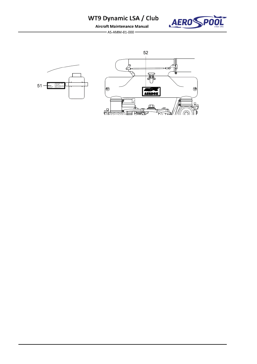
Fig. 11-5  Engine Compartment Placards 


CONTENTS 


SERVICING 

12  SERVICING 

CONTENTS 

GENERAL ......................................................................... 3


1.


INTRODUCTION ....................................................................... 3


2.


RECOMMENDED MATERIALS ................................................. 3


3.


DISPOSABLE REPLACEMENT PARTS ................................... 4


12-10


REPLENISHING ................................................................ 5


1.


DESCRIPTION .......................................................................... 5


2.


MAINTENANCE PRACTICES ................................................... 7


A.


Fuel system ....................................................................... 7


B.


Oil system ........................................................................ 10


C.


Engine cooling system .................................................... 16


D.


Tires ................................................................................ 19


E.


Brake system ................................................................... 20


12-20


SCHEDULED SERVICING .............................................. 21


1.


INTRODUCTION ..................................................................... 21


2.


SPECIAL TOOLS, MATERIALS .............................................. 21


3.


LUBRICATION CHART ........................................................... 22


4.


AIRCRAFT CLEANING ............................................................ 29


A.


Aircraft painted surfaces cleaning ................................... 29


B.


Cabin cleaning ................................................................. 30


C.


Interior cleaning ............................................................... 31


D.


Avionics care ................................................................... 31


E.


Engine cleaning ............................................................... 32


F.


Propeller cleaning ............................................................ 32


Effectivity:

 ALL 

12. 06. 2020


SERVICING 

12-30


UNSCHEDULED SERVICING ......................................... 33


1.


DESCRIPTION ........................................................................ 33


2.


MAINTENANCE PRACTICES ................................................. 33


A.


Winter maintenance ........................................................ 33


GENERAL 


SERVICING 

12-00


GENERAL


1.  INTRODUCTION 

This chapter provides instructions on how to replenish operating fluids. 
ln  addition,  this  chapter  provides  instructions  for  scheduled  servicing,  unscheduled 
servicing and recommended materials. 

2.  RECOMMENDED MATERIALS 

Tab.  12-1  shows  recommended  materials,  including  required  specifications, 
recommended by the aircraft manufacturer or the engine manufacturer. Any products 
with identical specifications can be used. Products given in Tab. 12-1 have been tested 
and approved for usage on aircraft. 
 

MATERIAL  DESIGNATION 

SPECIFICATION 

NOTE 

Fuel 

MOGAS 

NATURAL 95 
EN 228 Super 

For more specific 
information about 
usable fuel refer to 
Rotax Service 
Instruction No. SI-
912-016 

 the latest 

issue. 

AVGAS 

AVGAS 100 LL 
ASTM-D910 

Engine oil 

AeroShell Sport Plus 4 

API 

 SL 

SAE 10W-40 

For more specific 
information about 
usable oils refer to 
Rotax Service 
Instruction No. SI-
912-016 

 the latest 

issue. 

Coolant 

Conventional coolant 

Mobil Antifreeze 
Extra 

For more specific 
information about 
usable coolant refer 
to Rotax Service 
Instruction No. SI-
912-016 

 the latest 

issue. 

Hydraulic 
fluid 

Conventional hydraulic 
fluid 

DOT-4 
Classification J1703c 

Brake system 

Tab.


12-1


Recommended Materials 


Effectivity:

 ALL 

12. 06. 2020


SERVICING 

3.  DISPOSABLE REPLACEMENT PARTS 

Tab. 12-2 shows disposable replacement parts. Components given in Tab. 12-2 have 
been approved for usage on aircraft WT9 Dynamic LSA. 
 

COMPONENT 

SOURCE 

SPECIFICATION 

Air filter 

Sprint Filter 

P102 

Fuel filter 

MEFILTER 

DF12 

Oil filter 

BRP-Powertrain 

825016 

Spark plugs 

BRP-Powertrain 

297656 

Main wheel tire 

Any source 

15x6.00-6 

Nose wheel tire 

Any source 

13x5.00-6 

Accumulator 17 h 

CSB BATTERY CO., LTD. 

GP 12170 (12 V / 17 Ah) 

Accumulator 20 Ah 

GP 12220 (12 V / 20 Ah) 

Primary weak link 
(round hole) 

TOST GmbH 

110107 (300 

±

30 daN) 

110106 (400 

±

40 daN) 

Reserve weak link 
(oval hole) 

TOST GmbH 

110127 (300 

±

30 daN) 

110126 (400 

±

40 daN) 

Tow rope RED STAR 

TOST GmbH 

185400 (40 m, 1100 daN) 
185500 (50 m, 1100 daN) 
185600 (60 m, 1100 daN) 

Connecting ring pair 

TOST GmbH 

102000 (LN 65091) 

Brake pads 

Beringer 

Part No. ZEA01 

Tab.


12-2


List of Disposable Replacement Parts 


REPLENISHING 


SERVICING 

12-10


REPLENISHING


1.  DESCRIPTION 

This chapter provides replenishing information of all operating fluids of aircraft: 

  Fuel system 

  Oil system 

  Engine cooling system 

  Brake system 

For servicing points refer to Fig. 12-1 and Fig. 12-2. 


  Fuel tank caps 

  Overflow bottle cap 

  Nose tire inflation valve 

  Oil tank cap 

  Main tire inflation valve 

  Brake fluid reservoir cap 

  Brake caliper bleeding screw 

  Master cylinder bleeding screw 

  Expansion tank cap 

10 

  Pressure limiter bleeding screw 

Fig.  12-1  Servicing Points 


Effectivity:

 ALL 

04. 07. 2019


SERVICING 


Fig.


12-2


Drain Valves 


REPLENISHING 


SERVICING 

2.  MAINTENANCE PRACTICES 

A.  Fuel system 

Integral  fuel  tanks  are  located  in  both  wings  and  wing  central  section  in  front 
of main spar. Wing and wing central section tanks are interconnected with hose. 
Fuel tank cap is located on the top surface of the wing. Drain valves are placed 
in  the  lowest  point  of  each  tank  on  the  bottom  surface  of  wings  and  fuselage  
(Fig. 12-2). 
Fuel tanks capacities are shown in Tab. 12-3.  

ITEM 

LEFT TANK 

RIGHT TANK 

TOTAL 

U. S. gal 

U. S. gal 

U. S. gal 

Total fuel 

63.0 

16.65 

63.0 

16.65 

126.0 

33.29 

Usable fuel 

59.5 

15.72 

59.5 

15.72 

119.0 

31.44 

Unusable fuel 

3.5 

0.93 

3.5 

0.93 

7.0 

1.85 

Tab.  12-3  Fuel Quantity 

The fuels with min. RON 95 (min. AKI 91) can be used. The fuel specifications 
that can be used are listed in Tab. 12-4. 

FUEL 

DESCRIPTION 

MOGAS 

EN 228 super 
EN 228 super plus 

AVGAS 

AVGAS 100 LL 

Tab.  12-4  Fuel Specifications 

The fuels can contain dissolved and suspended water.  The  quantity  of  water  
in the fuel depends upon the temperature and type of fuel. The suspended water 
is settled  on the bottom of fuel tanks. Dissolved water dispersed in fuel cannot 
be filtered from the fuel by a fuel filter, which  is  able  to  catch  only microscopic 
solid particles. 
The risk of operation with a contaminated fuel can be reduced by: 

  Keeping the fuel servicing equipment and filters of such equipment clean 

  Proper storage of the fuel 

  Regular  drainage  (prior  to  drainage,  let  the  fuel  in  calm  position  

for  a  sufficient  period  of  time  for  impurities  and  suspended  water  to  settle 
down) 

  Regular  watching  for  signs  of  fuel  contamination  e.g.  fuel  filter  element 

condition, fuel drain sample, visual check of the tank inside etc. 

 
The  following  safety  information  should  be  followed  at  refueling/defueling, 
drainage, and another fuel handling:  


Effectivity:

 ALL 

12. 06. 2020


SERVICING 

WARNING 

GROUND  THE  EXHAUST  PIPE  OUTLET  AND  FUEL  SERVICE 
EQUIPMENT PRIOR TO AIRCRAFT REFUELING/DEFUELING! 
MAKE SURE THAT A SUITABLE FIRE EXTINGUISHER IS AVAILABLE  
AT ALL TIMES DURING AIRCRAFT REFUELING/DEFUELING! 
SMOKING  OR  MANIPULATING  WITH  OPEN  FIRE  DURING 
REFUELING/DEFUELING AND DRAINING IS PROHIBITED! 
MASTER  SWITCH  AND  IGNITION  MUST  BE  SWITCHED  OFF!  
NO PERSONS ALLOWED TO BE IN THE COCKPIT! 
DO  NOT  USE  THE  MATERIALS  WHICH  CAN  CAUSE  STATIC 
ELECTRICITY DURING REFUELING/DEFUELING AND DRAINING! 
DO NOT OPERATE ANY ELECTRICAL SWITCHES IN THE AIRCRAFT 
DURING REFUELING/DEFUELING OR DRAINING! 
IT  IS  PROHIBITED  TO  REFUEL  TANKS  IN  RAIN,  STORM,  CLOSED  
AND  INSUFFICIENTLY  AIRED  AREAS  (E.  G.  HANGAR),  AT  ENGINE 
RUN, AT ELECTRICAL INSTALLATION ON. 

CAUTION 

USE ONLY FUEL SUITABLE FOR THE RESPECTIVE CLIMATIC ZONE. 
RISK OF VAPOUR FORMATION IF USING WINTER FUEL FOR SUMMER 
OPERATION. 


(1)  Tanks refueling: 

Type of maintenance:  

Line 

Personnel qualification: 

Pilot/Owner 

qualified 

in 

accordance  

with M.A.803 or higher 

Recommended tools, materials, persons and documentation: 

ITEM 

QUANTITY 

Fire extinguisher 

1 pc 

Cotton cloth 

AR 

Persons 

Tab. 12-5 Recommended tools, materials, persons and documentation 

(a)  Shut down the engine. 
(b)  Set the brake lever to 

PARK

 position or install wheel chocks. 

(c)  Prior  to  refueling  the  tank  make  sure  that  the  corresponding  kind  

of fuel is used (Tab. 12-4). 

(d)  Electrically  ground  the  aircraft  (use  the  exhaust  pipe  outlet)  

to the grounding point. 

(e)  Remove the fuel tank cap (1, Fig. 12-1) on wing

s upper skin. 

(f) 

Refuel the tank from the fuel servicing equipment. 


REPLENISHING 


SERVICING 

(g)  Install  the  fuel  tank  cap  and  make  sure  that  opening  arm  directs 

rearward. 

(h)  Make sure that no spilled fuel is on the aircraft; clean if necessary. 

NOTE 

If refueling only one fuel tank, fill such fuel quantity that in both 
tanks will be same amount of fuel. 

(i) 

Remove the ground cable from the aircraft. 

(j) 

Remove wheel chocks. 

(2)  Tanks defueling: 

Type of maintenance:  

Line 

Personnel qualification: 

Independent 

certifying 

staff 

qualified  

in accordance with Part-66 or higher. 

Recommended tools, materials, persons and documentation: 

ITEM 

QUANTITY 

Fire extinguisher 

1 pc 

Fuel container 

1 pc 

Defueling tool 

1 pc 

Cotton cloth 

AR 

Loctite 577 

AR 

Persons 

Tab. 12-6 Recommended tools, materials, persons and documentation 

Fuel  tanks  are  defueled  by  means  of  fuel  drain  valves,  located  
in the lowest point of each tank on a wings bottom surface (Fig. 12-2). 
 
(a)  Shut down the engine. 
(b)  Set the brake lever to 

PARK

 position or install wheel chocks. 

(c)  Electrically  ground  the  aircraft  (use  the  exhaust  pipe  outlet)  

to the grounding point. 

(d)  Place a fuel container bellow the drain valve. 
(e)  Unscrew the drain valve from wing central section tank (A, Fig. 12-2), 

install the defueling tool and set it to open. 

(f) 

Open  the  fuel  tank  cap  (1,  Fig.  12-1)  on  the  wing  upper  side  
to accelerate defueling. 

(g)  When the fuel stops draining, remove defueling fixture. 
(h)  Drain the residual fuel from the wing tank (A, Fig. 12-2). 
(i) 

Clean the drain valves. Apply Loctite 577 on threads and screw the drain 
valves. 

(j) 

Remove the ground cable from the aircraft. 

(k)  Release 

PARK

 lever or remove wheel chocks. 


Effectivity:

 ALL 

24. 11. 2020


SERVICING 

B.  Oil system 

The engine Rotax 912 ULS2 uses a  dry sump  lubrication system with  total oil 
system  capacity  3.5  l.  A  filler  cap  and  dipstick  is  provided  for  determining  
the amount of oil in the system. 

WARNING 

ALWAYS  ALLOW  ENGINE  TO  COOL  DOWN  TO  AMBIENT 
TEMPERATURE  BEFORE  START  OF  ANY  WORK,  OTHERWISE 
YOU RISK BURNING FROM HOT PARTS. 
ENGINE IGNITION MUST BE SWITCHED OFF. 


(1)  Oil level check: 

Type of maintenance:  

Line 

Personnel qualification: 

Independent 

certifying 

staff 

qualified  

in accordance with Part-66 or higher. 

Recommended tools, materials, persons and documentation: 

ITEM 

QUANTITY 

Cotton cloth 

AR 

Persons 

Tab. 12-7 Recommended tools, materials, persons and documentation 

(a)  Level the aircraft (Chapter 08-10). 
(b)  Set the brake lever to 

PARK

 position or install wheel chocks. 

(c)  Open inspection door located in engine upper cowling. 
(d)  Unscrew the cap (2, Fig. 12-3) on oil tank (1), pull out dipstick (3) and 

clean it. 

(e)  Turn the propeller several times by hand in direction of engine rotation 

to  pump  all  the  oil  from  the  engine  to  the  oil  tank.  This  process  is 
completed  when  air  flows  back  to  the  oil  tank.  This  flow  can  be 
perceived as a murmur. 

(f) 

Put dipstick back in oil tank and check oil level. 

(g)  The oil level in the oil tank should be between the two marks (min. / 

max.) on the oil dipstick, but must never fall below the min. mark. 

(h)  If oil is below minimum level, replenish as required. 
(i) 

Fit the oil dipstick and tighten the oil tank cap by hand. 

(j) 

Close inspection door at upper engine cowling. 

(k)  Release 

PARK

 lever or remove wheel chocks.  


REPLENISHING 


SERVICING 

(2)  Oil replenish: 

Type of maintenance:  

Line 

Personnel qualification: 

Independent 

certifying 

staff 

qualified  

in accordance with Part-66 or higher. 

Recommended tools, materials, persons and documentation: 

ITEM 

QUANTITY 

New oil 

AR 

Cotton cloth 

AR 

Persons 

Tab. 12-8 Recommended tools, materials, persons and documentation 

NOTE 

For  longer  flights  replenish  oil  to  max.  mark  to  warrant  more 
reserve. Difference between min. and max. level marks is 0.5 l. 

(a)  Put the aircraft on leveled surface. 
(b)  Set the brake lever to 

PARK

 position or install wheel chocks. 

(c)  Open inspection door located on engine upper cowling. 
(d)  Unscrew the cap (2, Fig. 12-3) on oil tank (1), pull out dipstick (3) and 

clean it. 

(e)  Turn the propeller several times by hand in direction of engine rotation 

to  pump  all  the  oil  from  the  engine  to  the  oil  tank.  This  process  is 
completed  when  air  flows  back  to  the  oil  tank.  This  flow  can  be 
perceived as a murmur. 

(f) 

Replenish oil to the correct  level. Make sure that the corresponding 
kind of oil is used (Tab. 12-1). 

(g)  Put dipstick back in oil tank and check oil level. The oil level in the oil 

tank should be between the two marks (min. / max.) on the oil dipstick, 
but must never fall below the min. mark. 

(h)  Fit the oil dipstick and tighten the oil tank cap by hand. 
(i) 

Close inspection door at upper engine cowling. 

(j) 

Release 

PARK

 lever or remove wheel chocks.


Effectivity:

 ALL 

28. 04. 2021


SERVICING 


Fig.


12-3


Oil Level Check 

(3)  Oil change: 

Type of maintenance:  

Line 

Personnel qualification: 

Independent 

certifying 

staff 

qualified  

in accordance with Part-66 or higher. 

Recommended tools, materials, persons and documentation: 

ITEM 

QUANTITY 

Wrench 17 

1 pc 

Wrench 19 

1 pc 

Wrench 22 

1 pc 

Ignition wrench 16 

1 pc 

Oil filter wrench 

1 pc 

Jig 

1 pc 

Rags 

2 pcs 

Syringe 

1 pc 

New oil 

4 l 

New oil filter 

1 pc 

Cooper gasket ring 

Ø

14 mm 

3 pcs 

Safety wire 

Ø

0.8 mm 

AR 

Persons 

Maintenance Manual (Line Maintenance) for Rotax 
Engine Type 912 Series (Ref. No. MML-912) 

Tab. 12-8 Recommended tools, materials, persons and documentation 


1  Oil tank 
2  Oil tank cap 
3  Dipstick 


REPLENISHING 


SERVICING 

WARNING 

CARELESS  DRAINING  OF  HOT  ENGINE  OIL  MAY  CAUSE 
SCALDS.  DISPOSE  OF  USED  OIL  AND  FILTERS 
RESPECTING  THE  ENVIRONMENTAL  AND  SAFETY 
REGULATIONS. 

CAUTION 

FAILURE TO FOLLOW INSTRUCTIONS BELOW COULD LEAD 
TO  AIR  ENTERING  THE  OIL  SYSTEM  AND  DEFECTS  
ON VALVE TRAIN. 

NOTE 

Run engine to warm oil before beginning oil change procedure. 
Do  not  drain  the  oil  suction  line,  oil  radiator  and  return  line  
to avoid of air entering the oil system. 
Carry out the oil and filter change quickly and without interruption 
to prevent draining of the oil system from hydraulic tappets. 

(a)  Put the aircraft on leveled surface. 
(b)  Set the brake lever to 

PARK

 position or install wheel chocks. 

(c)  Check oil level (see 2.B.(1)). 
(d)  Remove engine cowlings (Chapter 71-10). 
(e)  Place a suitable container under the oil tank, remove the drain plug  

(9, Fig. 12-5) (quick drain valve if fitted) and drain oil out. 

(f) 

Turn the propeller several times by hand in direction of engine rotation 
to  pump  all  the  oil  from  the  engine  to  the  oil  tank.  This  process  is 
completed  when  air  flows  back  to  the  oil  tank.  This  flow  can  be 
perceived as a murmur. 

(g)  On oil cooler (2), remove safety wire and disconnect hoses (4; 5). Suck 

oil from oil cooler (2). 

(h)  Unscrew oil filter. 
(i) 

Install new oil filter: 

  clean the contact surface of the oil pump housing with a clean cloth 

  apply a thin film of engine oil on the gasket of a new oil filter 

  screw on oil filter until oil filter gasket is seated solidly 


tighten oil filter with 3/4 turn (270°)

(j) 

Cut old oil filter without producing any metal debris and inspect filter 
material for foreign objects. 

(k)  Remove  safety  wire,  unscrew  magnetic  plug  (Fig.  12-4),  check  

for metal contamination and refit, torque to 25 Nm. Secure magnetic 
plug using safety wire.  


Effectivity:

 ALL 

12. 06. 2020


SERVICING 

WARNING 

IF  METAL  CONTAMINATION  IS  FOUND  ON  PLUG  
(FIG. 12-4), CONTACT AIRCRAFT MANUFACTURER! 


Fig.


12-4


Magnetic Plug 

(l) 

Fill the oil cooler with new oil. Make sure that the corresponding kind 
of oil is used (Tab. 12-1). 

(m)  Connect  hoses  (4;  5,  Fig.  12-5)  on  the  oil  cooler  (2);  secure  them  

with safety wire. 

(n)  On bottom of oil tank screw the drain plug (9) with new gasket ring (10) 

torque to 25 Nm. Secure drain plug (9) with safety wire. 

NOTE 

During  tightening  of  drain  plug,  hold  upper  nut  with  second 
wrench. 

(o)  Remove cap (3), pour approximately 3 l of new oil into oil tank. Make 

sure to use corresponding kind of oil (Tab. 12-1); close the oil tank cap 
(3). 

(p)  On oil tank (1) disconnect  hose (7);  route disconnected hose under 

engine and put to suitable container. 

(q)  Seal up hose socket (10).


REPLENISHING 


SERVICING 

(r)  Remove  upper  spark plugs  from  every  cylinder  head  on  the  engine 

(refer to the Maintenance Manual (Line Maintenance) for Engine Type 
912 Series, Ref. No.: MML-912 for spark plugs removal information). 

(s)  On vent hose (8) put on jig making pressure at 0.45 bar. 

CAUTION 

PRESSURE SHOULD NEVERRISE OVER 1 BAR. 

(t) 

Rotate the propeller while beginning a continual flow of oil from hose 
(7). Add more oil if necessary. 

(u)  Disconnect jig, connect back hose (7) on oil tank and reinstall spark 

plugs;  tighten  spark  plugs  on  recommended  torque  moment  
(refer to the Maintenance Manual (Line Maintenance) for Engine Type 
912 Series, Ref. No.: MML-912 for spark plugs removal information). 

(v)  Check oil level (see 2.B.(1)). 
(w)  Install engine cowlings (Chapter 71-10). 
(x)  Release 

PARK

 lever or remove wheel chocks 


  Oil tank 

  Oil hose 

  Oil cooler 

  Venting hose 

  Oil tank cap 

  Drain plug 

  Oil hose 

10 

 Cooper gasket ring 

ø

14 mm 

  Oil hose  

11 

 Hose socket 

  Oil thermostat 


Fig.  12-5  Oil Change


Content      ..     7      8      9      10     ..