Takeuchi Hydraulic excavator TB1160W (Serial No. 514500002~). Operator's Manual (2016) - page 4
CONTROLS
ACCESSORIES
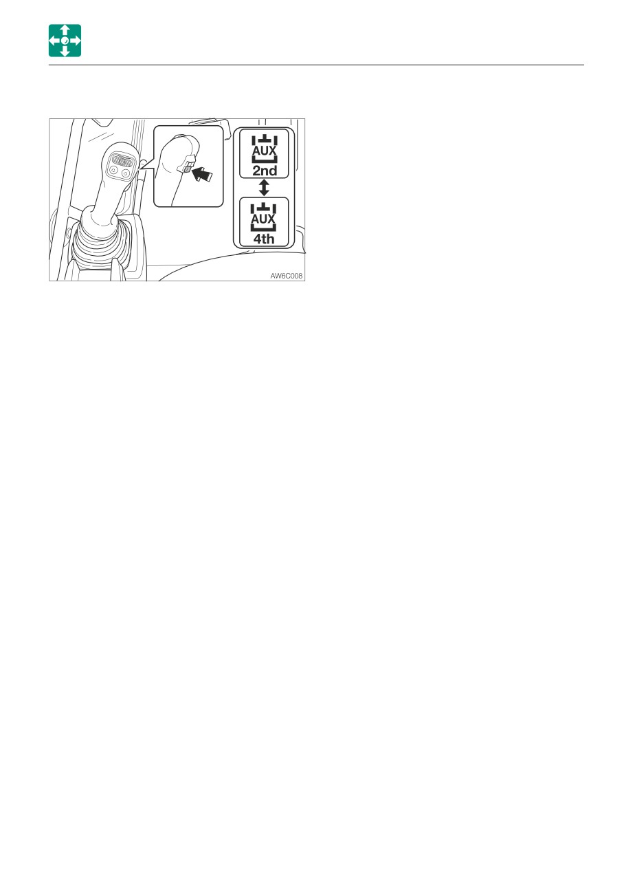
Auxiliary 2/4 select button (If equipped)
This button is used to switch the operation
between the second auxiliary and the fourth
auxiliary.
Pressing this button while the second
auxiliary symbol is displayed on the LCD will
switch to the fourth auxiliary operation.
Pressing this button one more time will
display the second auxiliary symbol on the
LCD to indicate that the second auxiliary
operation is resumed.
The actual operation is performed with the
2nd/4th auxiliary hydraulic switch (slider
switch).
Refer to “Second /Fourth auxiliary hydraulic
switch” on 2-44.
2-69
CONTROLS
ACCESSORIES
OPERATING THE MACHINE WITH AN
ACCUMULATOR
Be sure to handle the high-pressure
nitrogen gas enclosed in the accumulator
with care. If handled incorrectly, it could
explode and cause serious injury. Strictly
observe the following precautions:
• Do not disassemble.
• Do not allow flame near or throw it into
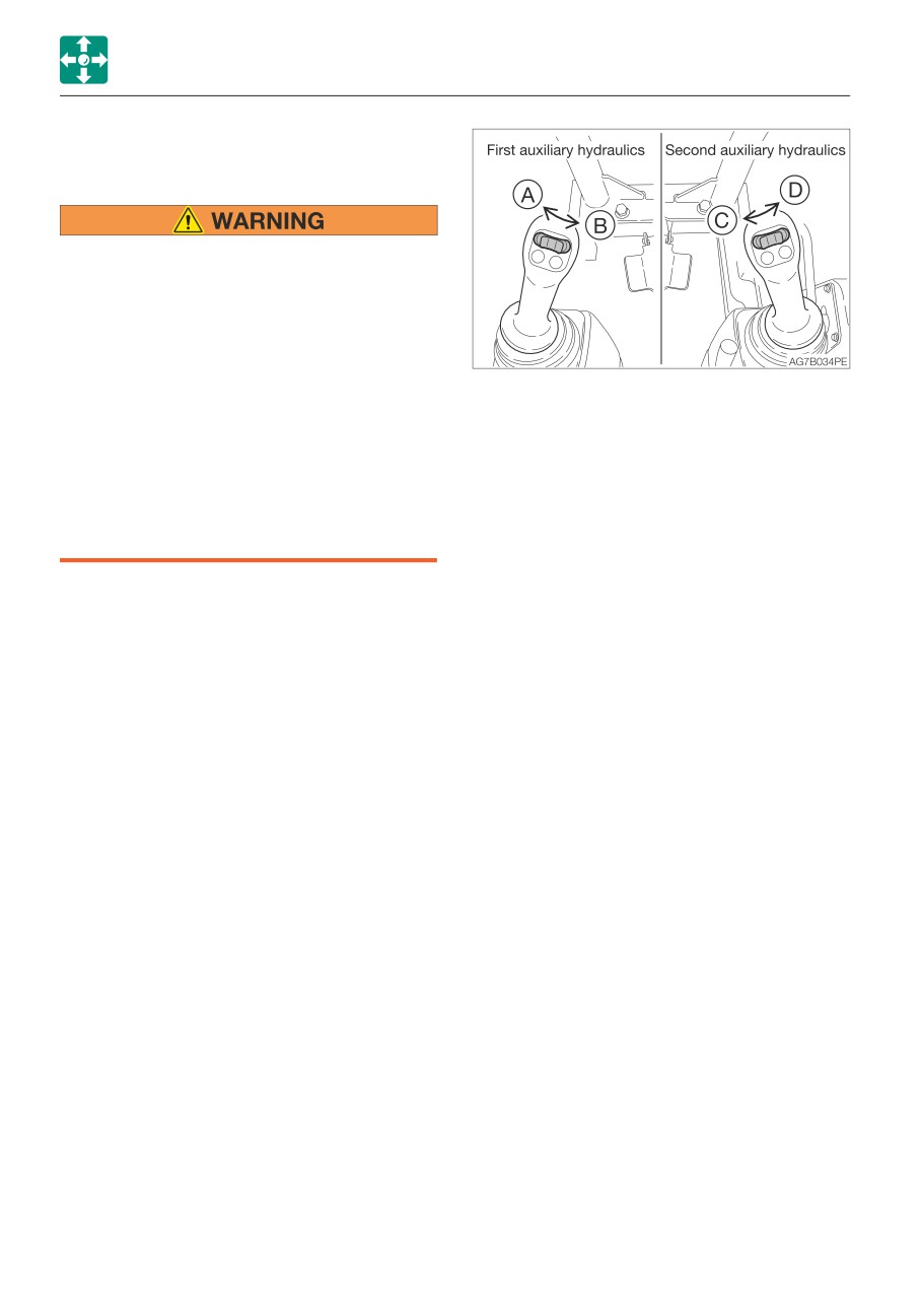
6. Move or press the auxiliary hydraulic
a fire.
switches several times to release the
• Do not drill, weld or fuse.
residual pressure in the circuitry.
• Do not subject it to physical shock such
7. Move all the control levers and pedals
as hitting, rolling or dropping.
several times in all directions to release the
• Before disposing of the unit, the sealed
pressure from the working equipment
gas must be drained. Contact a
circuitry.
Takeuchi service agent for help.
8. Raise the safety lock lever to engage the
lock.
For a machine with an accumulator, the
residual pressure in the auxiliary hydraulic
Lowering the boom when the engine has
circuit or the working equipment circuit can
stopped
be released even after the engine is stopped,
Perform this operation within 10 minutes
provided that the releasing is done within 10
after the engine stopping.
minutes after the engine is stopping.
1. Sit at the operator’s seat.
2. Turn the starter switch to the ON position.
Releasing residual pressure
3. Lower the safety lock lever to the unlock
Residual pressure refers to the pressure that
position
remains in the hydraulic circuit after the
4. Slowly push the operating lever forward to
operation. Release the residual pressure as
lower the boom.
necessary by using the following steps.
Perform the residual pressure releasing
within 10 minutes after the engine stopping.
1. Return the throttle controller to idle the
engine at low speed.
2. Lower the bucket and dozer blade to the
ground.
3. Check that the safety lock lever is in the
released position.
4. Stop the engine.
5. Turn the starter switch to the ON position.
2-70
CONTROLS
ACCESSORIES
LOAD SAFETY DEVICE
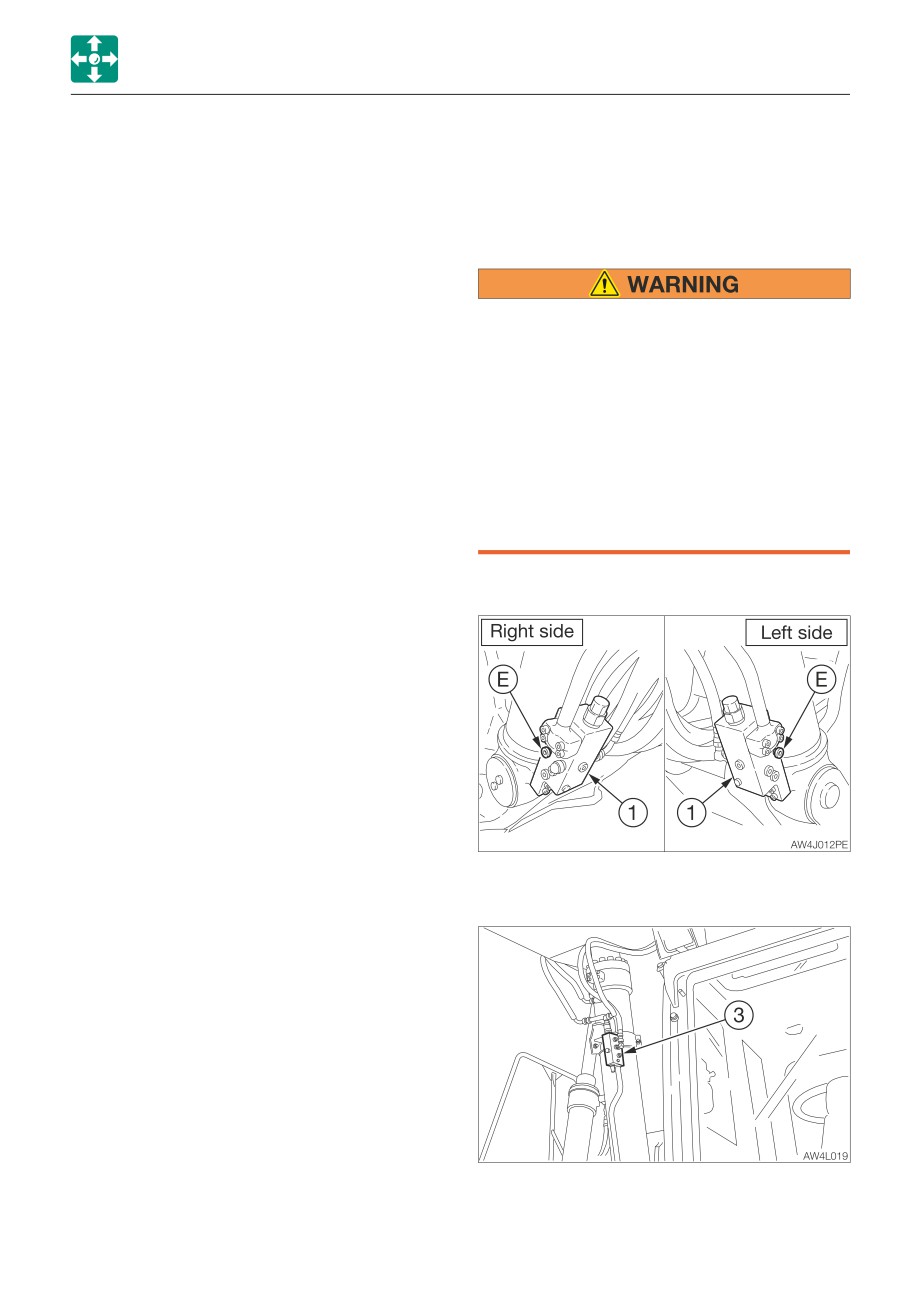
Emergency shut-off valve
If the boom, second boom or arm cylinder
The load safety devices include an
hose for lifting is ruptured, the emergency
emergency shut-off valve and an overload
shut-off valve is activated to prevent the
warning device. The emergency shut-off
boom, second boom or arm from falling
valve prevents the boom, second boom or
rapidly.
arm from falling rapidly. The overload
warning device sounds an alarm when an
excessive load is detected.
• If the boom or arm stops due to the
breakage of hose, immediately move
away from the load being lifted and go
to a safe location.
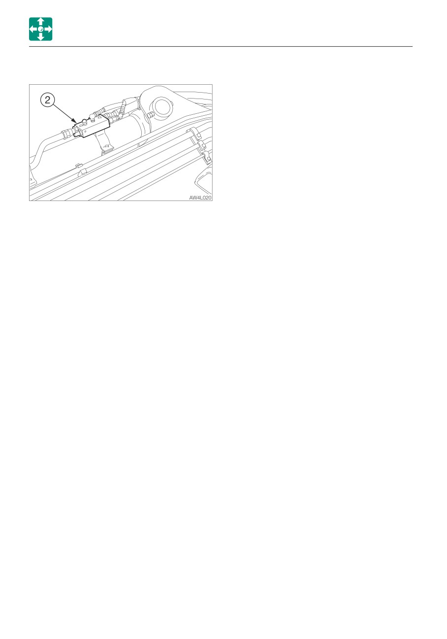
• Since the emergency shut-off valve (1),
(2) or (3) is a safety device, you must not
disassemble it and/or replace or adjust
its internal part. Takeuchi shall not be
held responsible for any injuries,
accidents or product malfunction
caused by disassembly.
Boom
Second boom (2-Piece boom)
2-71
CONTROLS
ACCESSORIES
Arm
Overload warning switch
Refer to “Overload warning switch” on page
2-45.
If the hose breaks and the emergency shut-
off valve (1), (2) or (3) is activated to stop the
operation of boom or arm, lower the boom
or arm by slowly operating the lever while
ensuring safety. Ask your sales or service
dealer for repair.
2-72
CONTROLS
ACCESSORIES
OUTRIGGER
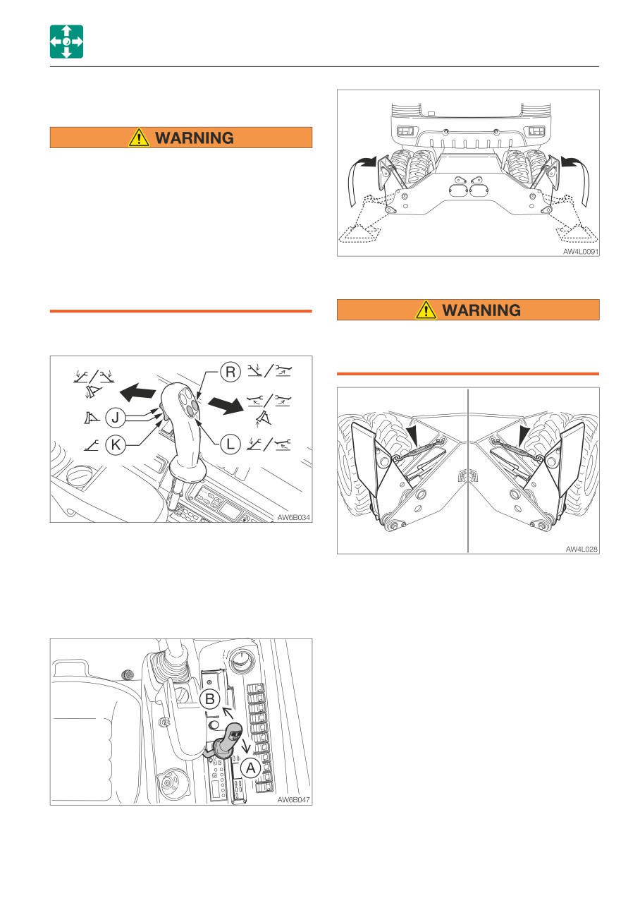
• Select a firm and uniform ground for
outrigger pads (surfaces to contact the
ground).
• When traveling on a public road, secure
the outriggers with the turnbuckles.
When retracting the outriggers, make
sure that the outrigger pads (the
surfaces to contact the ground) are
within the machine width. Failure to do
Turnbuckles
so could cause minor collisions.
Outrigger switch
When traveling on a public road, retract
the outriggers within the machine width
and install the turnbuckles.
(J)
Dozer blade operation (both sides)
(K)
Outrigger operation (both sides)
(L)
Left outrigger operation
Remove the turnbuckles before lowering the
(R)
Right outrigger operation
outriggers. Failure to do so could damage
the turnbuckles.
Operation
The outrigger operation is done by the blade
lever.
(A)
Outriggers Raise
(B)
Outriggers Lower
2-73
CONTROLS
ACCESSORIES
FUEL SUPPLY PUMP
This device automatically supplies fuel to the
fuel tank and stops automatically when the
fuel tank is full.
Do not use the fuel supply pump for
gasoline or hydraulic oil. Doing so could
result in explosion or damage.
Only use the fuel supply pump for diesel
fuel.
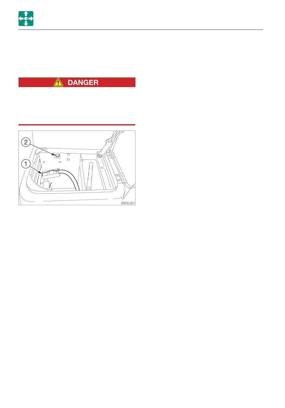
1. Open the front cover.
2. Insert the pump’s nozzle (1) in the fuel
supply tank.
3. Press the switch (2).
The pump stops automatically once the
fuel tank is full.
2-74
OPERATION
3-1
OPERATION
BEFORE STARTING OPERATION
WALK-AROUND INSPECTION
BEFORE STARTING
Perform the walk-around inspections once a
OPERATION
day before starting the engine for the first
GETTING ON OR OFF THE MACHINE
time that day.
Refer to “MAINTENANCE, Walk-around
inspection”, on pages 5-18 and 5-19.
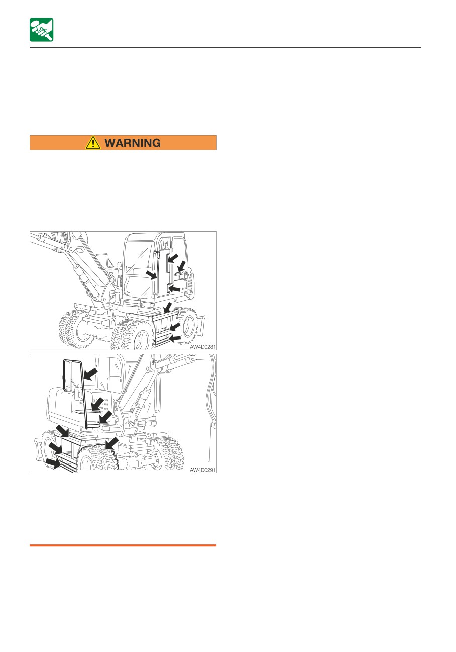
• Do not jump on or down from the
machine. Never attempt to get on or off
DAILY INSPECTION
the moving machine.
• When getting on or off the cab, first fully
Perform the daily inspections once a day
open the door to the locked position
before starting the engine for the first time.
and check that it does not move.
Refer to “MAINTENANCE, Daily inspection”,
on pages 5-20 to 5-27.
• Climb up/down the steps holding the
handrail to support your weight in a
three point secure stance (hand and
feet).
• Never use the safety lock lever or
control levers as hand holds.
3-2
OPERATION
STARTING AND STOPPING THE ENGINE
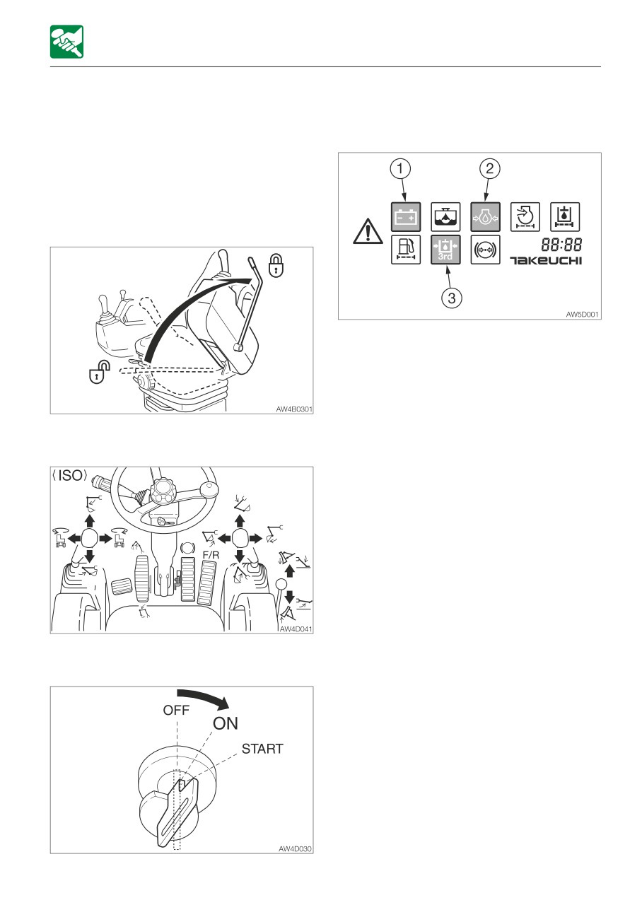
5. Insert the key into the starter switch, turn it
STARTING AND STOPPING
to the ON position, and then perform the
following inspections:
THE ENGINE
BEFORE STARTING THE ENGINE
1. Adjust the seat for a comfortable operating
position.
2. Fasten the seat belt.
· An alarm is sounded for two seconds.
The meters also start functioning. After
two seconds, only the battery charge
warning lamp (1), engine oil pressure
warning lamp (2) and third auxiliary
hydraulic warning lamp (3) start flashing,
3. Check that the safety lock lever is in the
and the other lamps turn off.
locked position.
The battery charge warning lamp (1),
engine oil pressure warning lamp (2) and
third auxiliary hydraulic warning lamp (3)
remain lit until the engine starts.
· Turn the light switch to check that the all
lights/lamps are lit
· Check the fuel level.
If a lamp does not light or the alarm is not
sounded, the display or a wire may be
damaged. Ask your sales or service dealer
for repair.
4. Check that all levers and pedals are in the
neutral position.
3-3
OPERATION
STARTING AND STOPPING THE ENGINE
STARTING THE ENGINE
press the deceleration button to cancel
the deceleration mode.
Starting in cold climates
• Clear all personnel from the work area.
• Sound the horn to warn people around
the machine.
Never use starting fluid on this engine, as
the starting fluid could cause an
IMPORTANT: Do not run the starter motor
explosion.
for more than 15 consecutive seconds. If
the engine fails to start, wait for 30
seconds, and then try again to start the
engine.
IMPORTANT: If the engine stalls due to
fuel shortage, add fuel, turn the key to the
ON position for 60 seconds, and then turn
it to the START position. Running the
starter for a long time before there is
enough fuel is going through can cause
the starter to fail.
Normal starting
1. Turn the throttle controller to the middle
position.
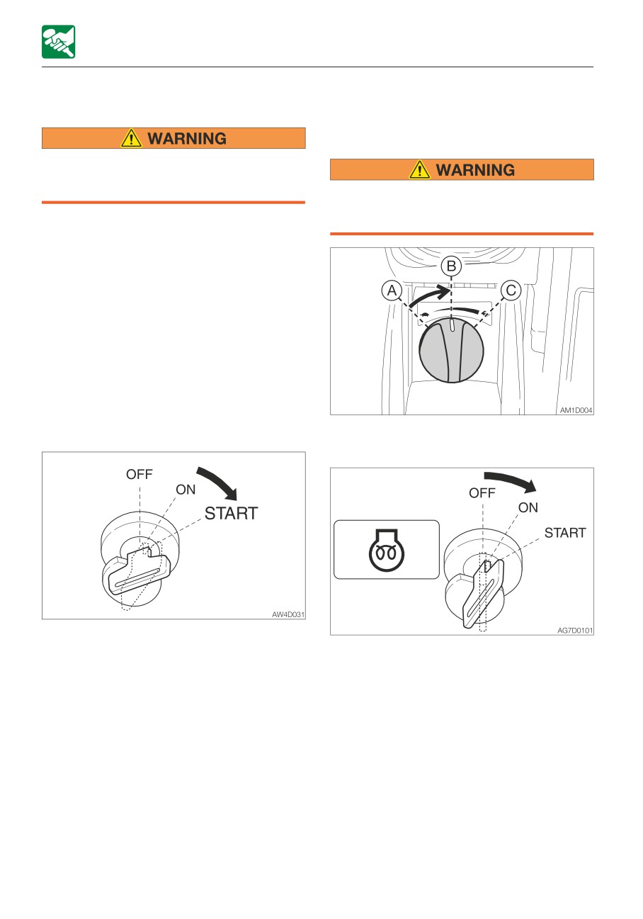
1. Turn the starter key to the START position
and start the engine.
2. Turn the starter key to the ON position,
2. Once the engine starts, release the key.
and confirm that the glow lamp is on. (The
The key automatically returns to the ON
glow lamp stays lit for 12 seconds when
position.
the coolant temperature is -10°C (14°F).)
3. Check that the warning lamps are off.
3. After the glow lamp goes out, press the
For safety reasons, it is designed that the
deceleration button (to cancel the
deceleration function is activated to set
deceleration mode), and then turn the key
the engine revolutions to low idling
to the START position to start the engine.
whenever the engine is started.
4. Once the engine starts, release the key.
Cancel the deceleration mode by pressing
The key automatically returns to the ON
the deceleration button as necessary.
position.
4. Warm up the engine.
5. Check that the warning lamps are off.
Refer to “Warming up the engine” on page
6. Return the throttle controller to the original
3-5.
position and warm up the engine.
5. After the completion of the warming up,
Refer to “Warming up the engine”.
3-4
OPERATION
STARTING AND STOPPING THE ENGINE
WARMING UP THE ENGINE
STOPPING THE ENGINE
IMPORTANT: Avoid racing the engine until
IMPORTANT: Do not stop the engine
it has warmed up.
suddenly when operating with heavy
Do not warm up the engine for a long time
loads or at the maximum speed. Doing so
(20 minutes or more). When idling is
may cause the engine to overheat or
required, occasionally place a load or run
seize. Never stop running the engine
the engine at medium speed.
suddenly except in emergency.
1. Return the throttle controller, and then run
1. Return the throttle controller.
at a low idle with no load for 10 minutes.
2. Idle the engine for about 5 minutes to
gradually let it cool.
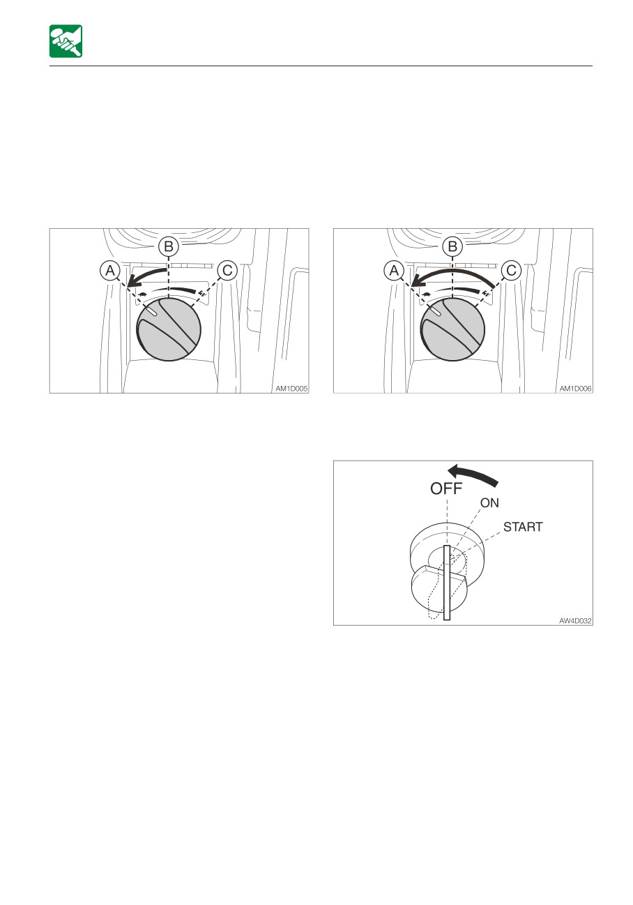
3. Turn the starter key to the OFF position to
stop the engine.
3-5
OPERATION
OPERATING THE MACHINE
OPERATING THE MACHINE
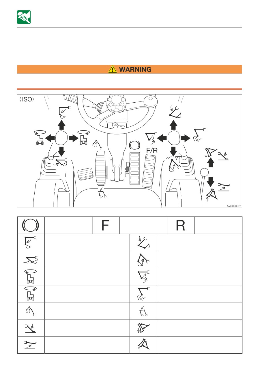
LEVER PATTERN (ISO PATTERN)
• Before starting operation, carefully check which lever pattern you are going to use.
• It is described using the ISO pattern in this manual.
Brake
Forward Travel
Reverse Travel
Arm Out
Boom Lower
Arm In
Boom Raise
Upperstructure Slew Left
Bucket Load
Upperstructure Slew Right
Bucket Dump
Second Boom Raise
Second Boom Lower
(2-piece boom)
(2-piece boom)
Outrigger Lower
Dozer Blade Lower
Outrigger Raise
Dozer Blade Raise
3-6
MEMO
3-7
OPERATION
OPERATING THE MACHINE
WARMING UP THE MACHINE
(HYDRAULIC OIL)
Operating the working equipment without
warming up the machine (hydraulic oil) is
dangerous, as the working equipment
cannot response to controls quickly or
may move in unexpected ways, and the
safety devices may not operate properly.
Be sure to sufficiently warm up the
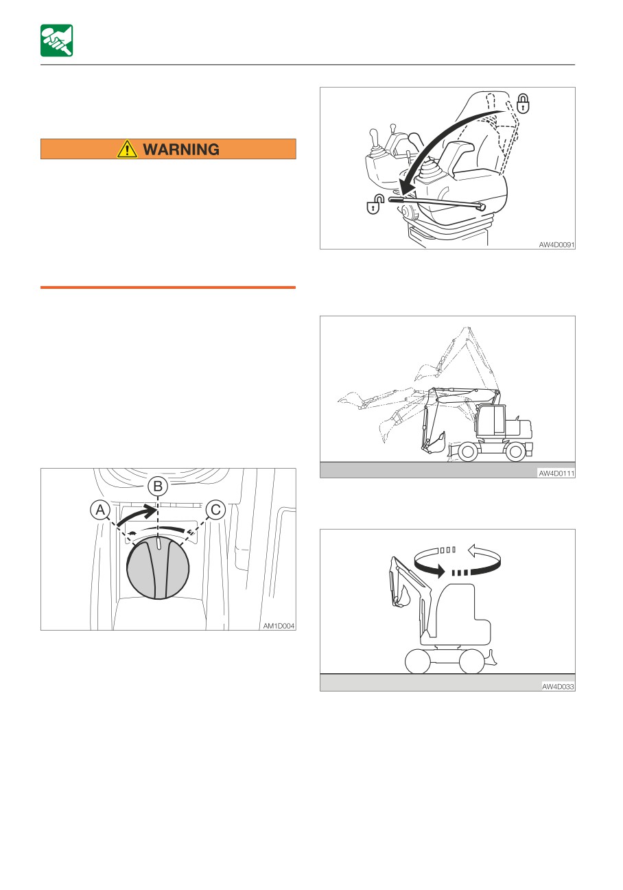
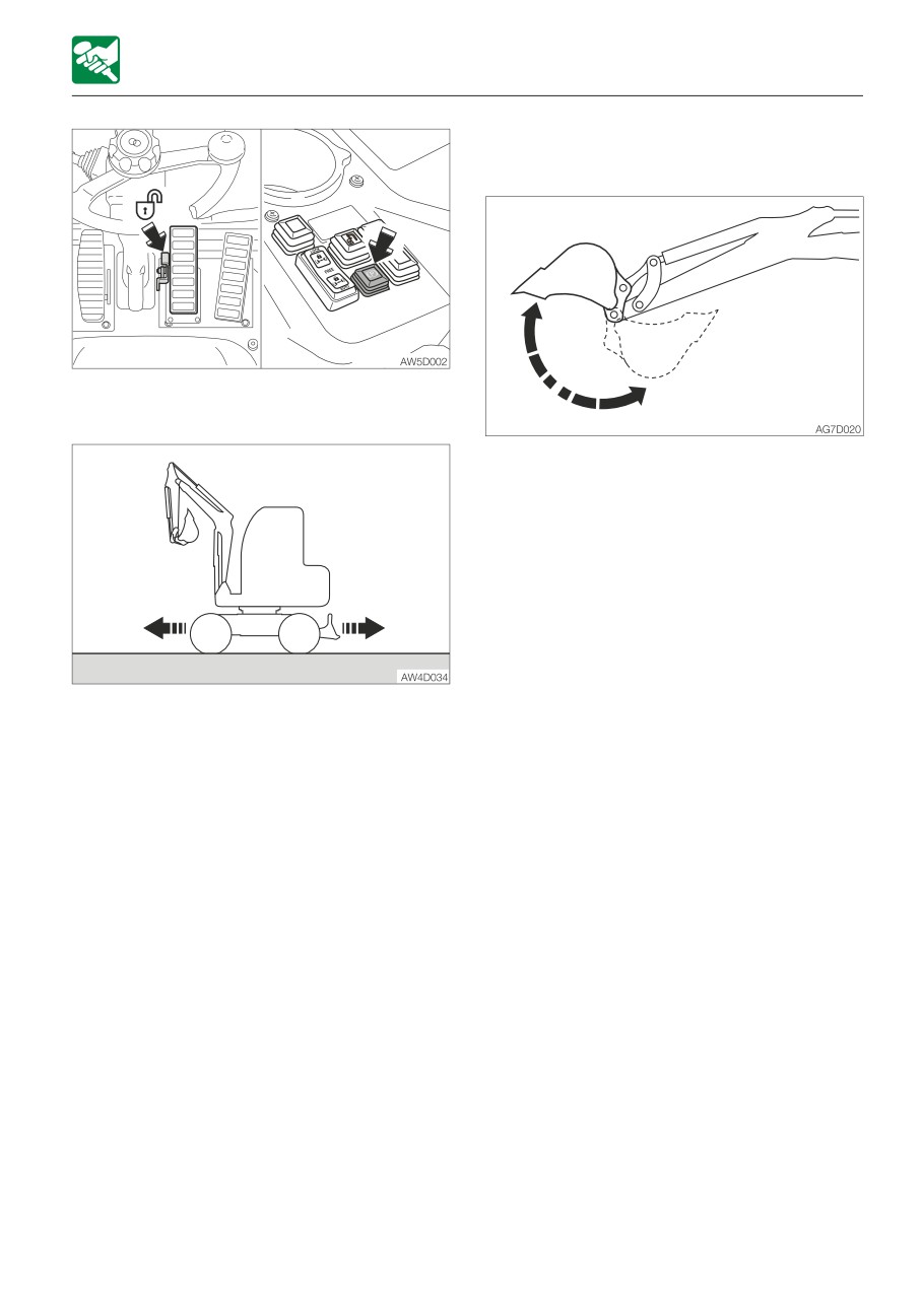
2. Fully lower the safety lock lever to
machine.
disengage the lock and lift the bucket from
the ground.
IMPORTANT: Do not operate the levers
too quickly when the hydraulic oil
temperature is below 20°C (68°F). The
proper hydraulic oil temperature during
operation is 50 to 80°C (122 to 176°F). If
operations must be performed at lower
temperatures, heat up the hydraulic oil to
at least 20°C (68°F).
Normal warm-up
3. Extend and retract each of the cylinders
slowly several times with no load.
1. Turn the throttle controller to the middle
position, and then run the engine at
medium speed for about five minutes with
no load.
4. Slew slowly to the left and the right several
times.
3-8
OPERATION
OPERATING THE MACHINE
Warm-up in cold climates
1. Perform the normal warm-up procedure.
5. Disengage the locks of the brake pedal
and the parking brake.
2. Set the bucket cylinder at the stroke end
and keep it there.
Do not keep this condition for more than
30 seconds.
3. Repeat Step 2 until the bucket operating
speed becomes normal.
6. Travel slowly forward and in reverse
several times.
3-9
OPERATION
OPERATING THE MACHINE
INSPECTION AFTER WARM-UP
After warming up the engine and machine
(hydraulic oil), perform the checks and
inspections described below, and repair if
necessary.
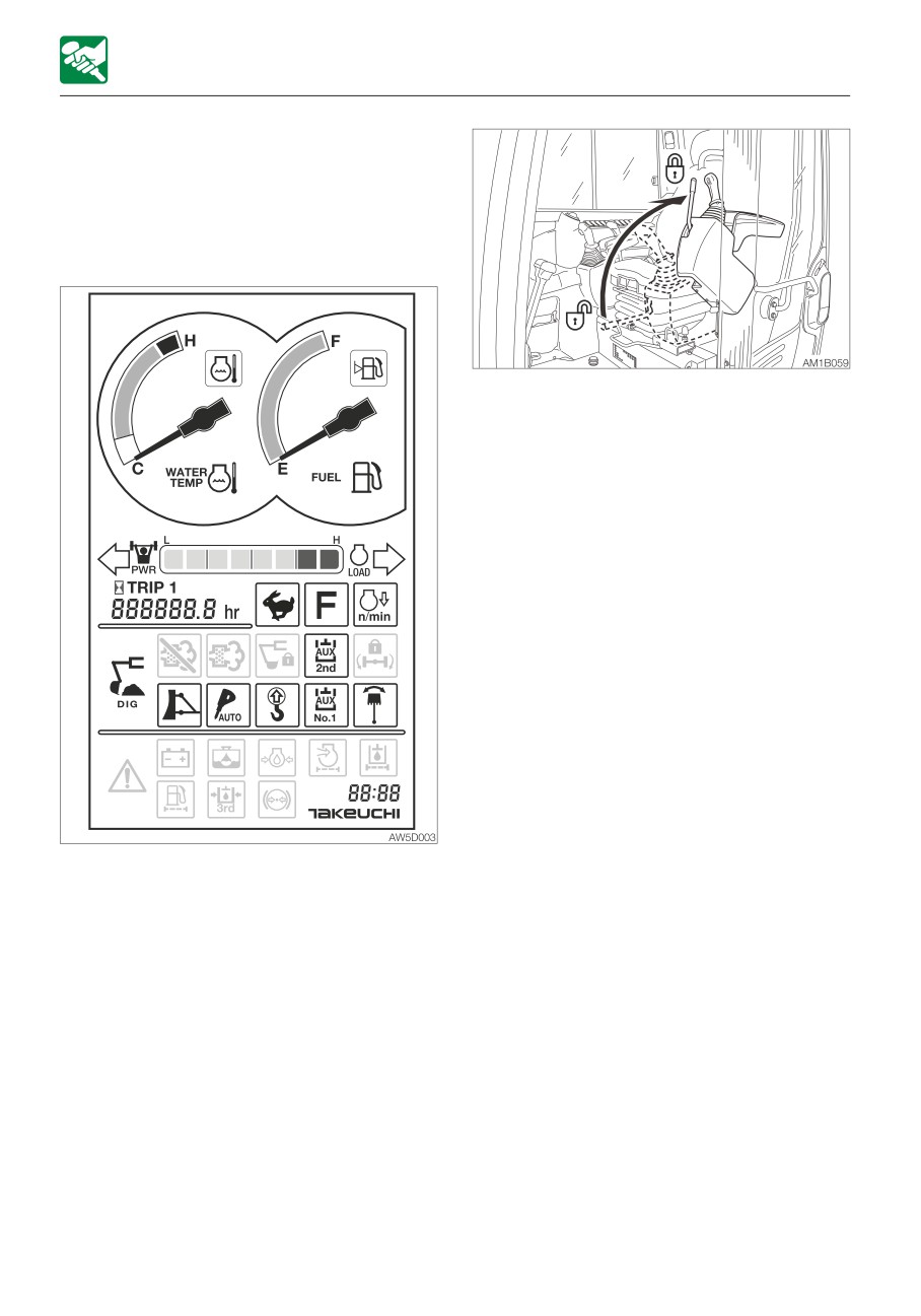
3. Raise the safety lock lever to the locked
position, and then check that the
operating and travel levers are locked.
1. Check that the warning lamps and meters
are as follows:
· Are all warning lamps off?
· Is the water temperature level within the
green range?
2. Check that there are no irregularities in the
exhaust color, sound and vibrations.
3-10
OPERATION
OPERATING THE MACHINE
TRAVELING THE MACHINE
• Before traveling, set the machine to the
“travel posture”.
Refer to “Preparing for travel” for further
details.
• When traveling on a road, be sure to
lock the working equipment. If any of
the controls is accidentally touched
when it is unlocked, the machine may
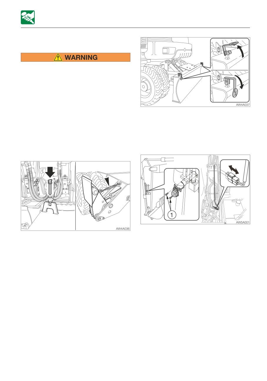
• Before traveling on a road, tilt the
suddenly move and cause serious injury
reflector. When operating at a job site,
or death.
raise the reflector to prevent it from
• Keep in mind that the steering wheel
being damaged.
operation is not possible when the
engine is stopped or if the steering
<For Germany>
pump becomes faulty.
• When traveling during nighttime hours,
• When traveling on a public road, be sure
be sure to install the position lights.
to lock slewing with the slew lock pin.
To prevent damage, remove the position
For machines with outriggers, retract
lights (including the brackets and
the outriggers within the machine width
harness) before working at the site.
and install the turnbuckles.
· Make sure that the outrigger pads (the
• Never allow anyone to enter the
sections to contact the ground) are
machine’s slewing radius and path.
within the machine width. Failure to do
• Signal your intention to move by
so could cause minor collisions.
sounding the horn.
• There is a blind spot in the rear of the
machine. Check that the area is safe
and clear for yourself. When necessary,
use the rear camera.
3-11
OPERATION
OPERATING THE MACHINE
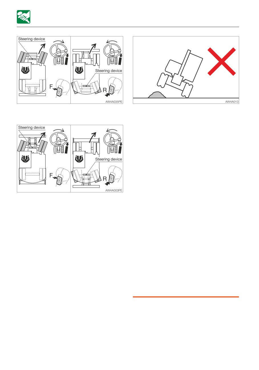
• Avoid crossing over obstacles whenever
Equipped with outrigger
possible. If you must do so, keep the
hoe attachment close to the ground
level and travel slowly. Never cross
obstacles which will tilt the machine to
an angle of 10° or greater.
• Avoid starting, stopping or changing
directions abruptly and maintain a
proper speed. Otherwise, the working
equipment may come in contact with
the ground, causing the machine to lose
its balance and get damaged or to
damage the structures in the
surrounding area.
• Before operating the travel pedal, make
• When traveling on the uneven road or
sure that the steering device is to the
sharp slope, turn off the deceleration
front of the operator’s seat. Remember
switch and the auto-deceleration
that when the steering device is to the
switch. If the machine is operated on
rear of the operator’s seat, the steering
such roads with these switches turned
wheel must be operated in the reverse
on, the engine speed may increase,
direction from when it is to the front.
causing the machine to travel
• Do not raise the safety lock lever or turn
unexpectedly rapidly (for machines with
the starter switch to the OFF position
the deceleration and auto-deceleration
while traveling. Doing so is dangerous
switches).
because it activates the parking brake
• When traveling on a road, know and use
and causes the machine to stop
the signaling devices required on the
suddenly.
machine. Use an escort vehicle for road
travel when required.
• Clear all obstacles from the path of the
machine.
3-12
OPERATION
OPERATING THE MACHINE
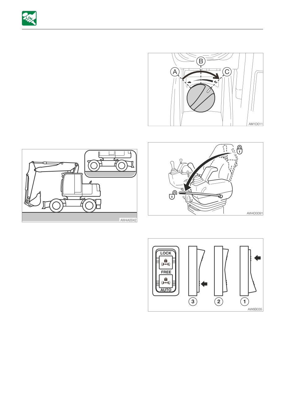
Preparing for travel
Moving forward and in reverse
1. Set the steering device facing forward and
to the front of the operator’s seat.
2. Fully raise the boom, fully lower the
second boom, and then set the arm
vertically to rollback the bucket.
3. Fully raise the blade/outriggers (if
equipped).
For machines equipped with outriggers,
secure them with turnbuckles.
4. Engage the slew lock.
5. Tilt the reflector.
1. Increase the engine speed.
Travel Posture
2. Fully lower the safety lock lever to
disengage the lock.
3. Press the ram lock switch to the neutral
position to disengage the ram lock.
3-13
OPERATION
OPERATING THE MACHINE
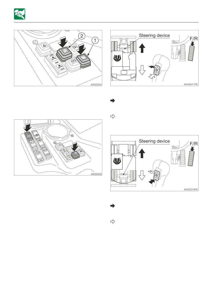
4. Press the travel pedal button (1) while the
When the steering device is in front of the
brake pedal is depressed.
operator’s seat:
(When entering the foot accelerator mode)
To move forward:
5. Press the attachment lock button (2) to
Press the travel select button (F) and
lock the working equipment.
step on the travel pedal.
To move in reverse
Press the travel select button (R) and
step on the travel pedal.
6. Press the low/high-speed travel switch to
choose the proper speed.
7. Press the parking brake button to
disengage the parking brake.
When the steering device is behind the
8. Operate the travel pedal as follows.
operator’s seat:
To move forward:
Press the travel select button (R) and
step on the travel pedal.
To move in reverse:
Press the travel select button (F) and
step on the travel pedal.
3-14
OPERATION
OPERATING THE MACHINE
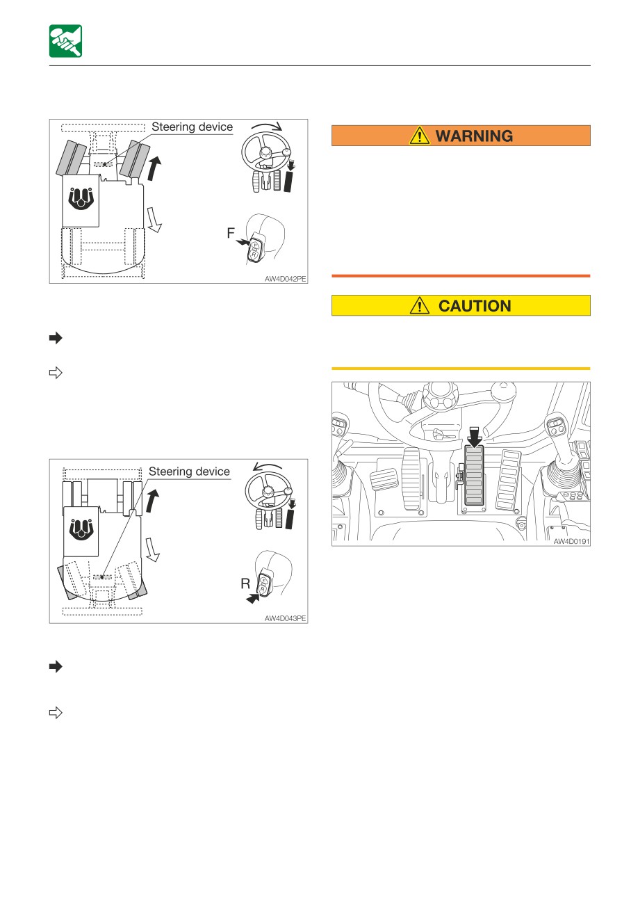
Turning
STOPPING TRAVEL
• Park the machine on a flat, rigid and
safe ground. Set the parking brake. If
you must park on a slope, chock the
tracks to block the machine.
• If any of the controls is accidentally
touched when it is unlocked, the
machine may suddenly move and cause
serious injury or death.
When the steering device is in front of the
operator’s seat:
To turn forward to the right:
Never stop running the machine suddenly
Press the travel select button (F) and turn
except in emergency. Stop in good time,
the steering wheel to the right.
if possible.
To turn backward to the right:
Press the travel select button (R) and
turn the steering wheel to the right.
To turn to the left, turn the steering wheel to
the left.
1. Slowly step on the brake pedal to stop the
machine.
2. Depress the brake pedal all the way down
to lock it.
When the steering device is behind the
operator’s seat:
To turn forward to the right:
Press the travel select button (R) and
turn the steering wheel to the left.
To turn in reverse to the right:
Press the travel select button (F) and turn
the steering wheel to the left.
To turn to the left, turn the steering wheel to
the right.
3-15
OPERATION
OPERATING THE MACHINE
OPERATING THE WORKING EQUIPMENT
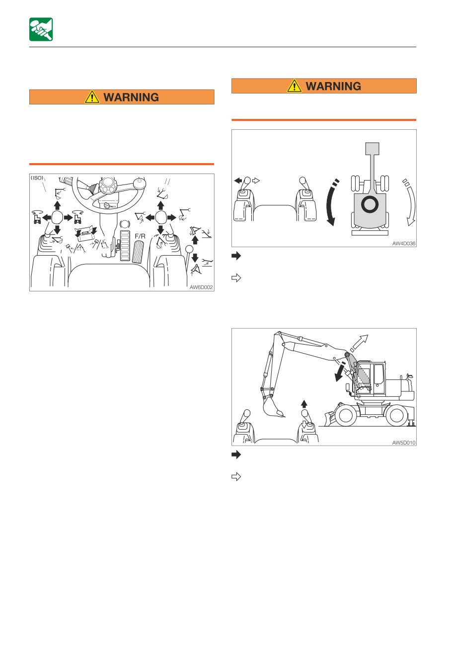
Slewing
Check the surrounding area for safety
• Before starting operation, carefully
before slewing.
check which lever pattern you are going
to use.
• It is described using the ISO pattern in
this manual.
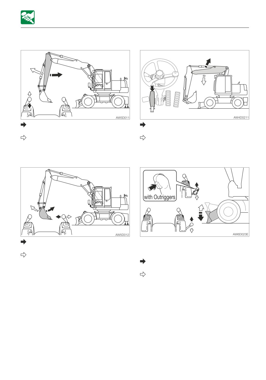
Upperstructure slew left:
Tilt the left operating lever to the left.
Upperstructure slew right:
Tilt the left operating lever to the right.
Use the right operating lever to operate the
boom and bucket.
Operating the boom
Use the left operating lever to operate the
arm and slewing.
Return the operating levers to the neutral
position to stop the working equipment.
1. Release the slew lock pin.
2. Depress the brake pedal all the way down
to engage the pedal lock.
3. Press the ram lock switch to lock the
suspension of the front axle.
4. Lower the dozer blade to the ground.
5. Lower the safety lock lever to the unlock
position.
Boom lower:
Tilt the right operating lever forward.
Boom raise:
Tilt the right operating lever backward.
3-16
OPERATION
OPERATING THE MACHINE
Operating the arm
Operating the second boom
Arm in:
Second boom raise:
Tilt the left operating lever backward.
Step on the toe side of the pedal.
Arm out:
Second boom lower:
Tilt the left operating lever forward.
Step on the heel side of the pedal.
Operating the bucket
Operating the dozer blade
Bucket load:
For machines with outriggers, select the
Tilt the right operating lever to the left.
dozer blade operation with the outrigger
Bucket dump:
switch.
Tilt the right operating lever to the right.
Dozer blade lower:
Tilt the blade lever forward.
Dozer blade raise:
Tilt the blade lever backward.
3-17
OPERATION
OPERATING THE MACHINE
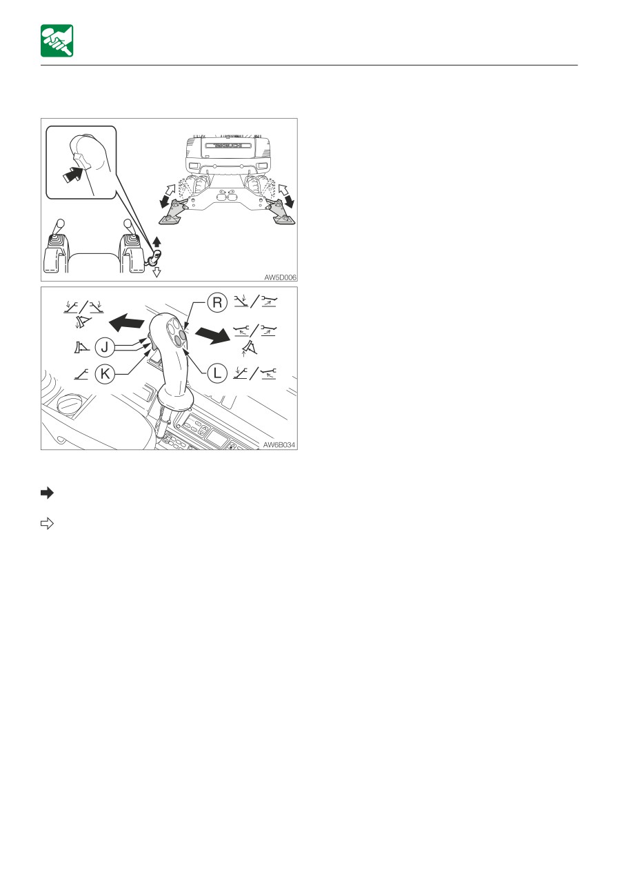
Operating the Outrigger (If equipped)
Select the outrigger operation with the
outrigger switch.
Outrigger lower:
Tilt the blade lever forward.
Outrigger raise:
Tilt the blade lever backward.
· Outrigger switch L:
Operating only the left side outrigger
· Outrigger switch R:
Operating only the right side outrigger
3-18
OPERATION
OPERATING PROCEDURES
Be gentle when using the hydraulic
OPERATING PROCEDURES
cylinder
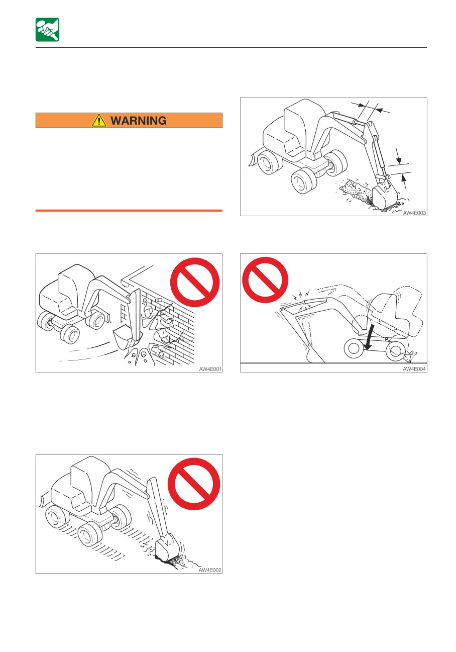
PROHIBITED OPERATIONS
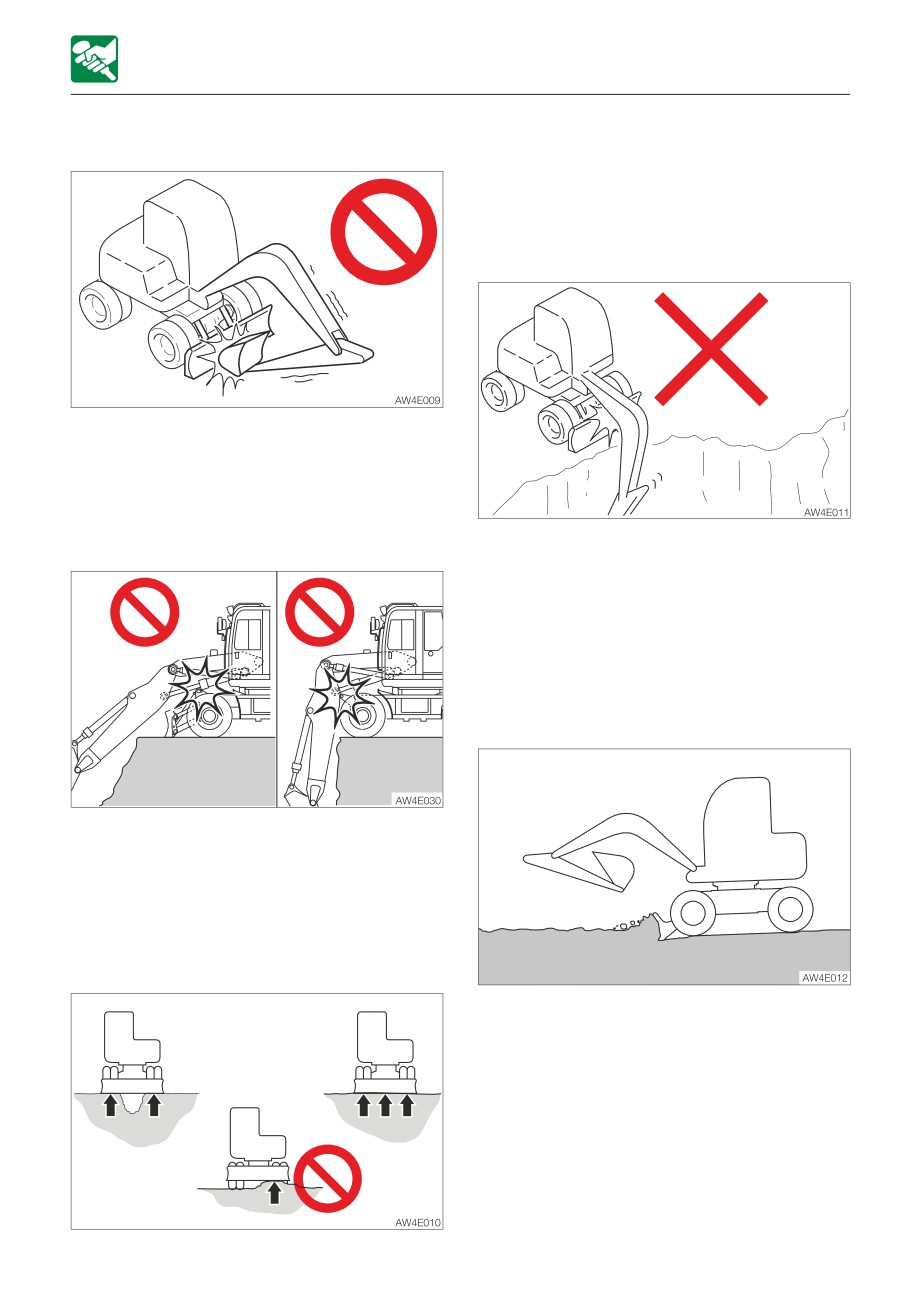
• Do not operate on bedrock (hard or
soft).
• Do not slew while traveling. If you must
operate the hoe attachment while
traveling, operate at speeds slow
enough so you have complete control at
all times.
Do not perform demolition or leveling
Do not extend the hydraulic cylinders to the
using slew force
stroke ends. Operate them with leeway.
Do not demolish walls or level ground using
Do not support the machine body with the
slew force. Also, do not dig the bucket teeth
hoe attachment when the body is lowering
into the ground during slewing. Doing so will
with the arm cylinder fully extended. Doing
damage the hoe attachment.
so concentrates the load on the arm cylinder
and could damage the arm cylinder.
Do not dig while traveling
Do not dig the bucket into the ground and
use the traveling force to dig.
3-19
OPERATION
OPERATING PROCEDURES
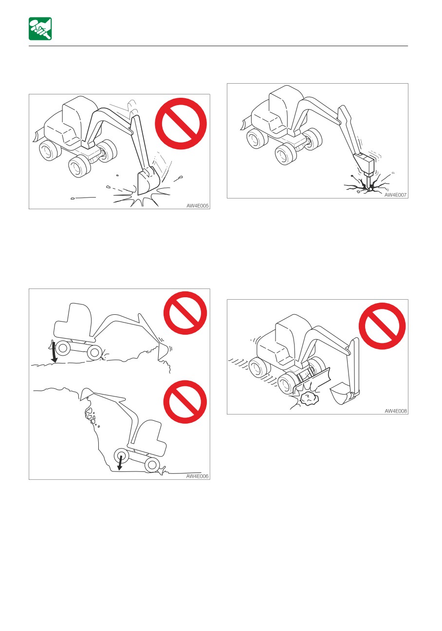
Do not drive piles with the bucket or dig
Digging bedrock
by banging the bucket
For hard base rock, break the rock up into
Doing so will shorten the service life of the
small pieces with a breaker, etc., before
hoe attachment. Use the hydraulic force to
digging. This prevents damage to the
dig.
machine and is thus more economical in the
end.
Do not perform operations using the
machine’s dropping force
Caution on exposing the dozer blade to
shocks
Hitting the dozer blade against rocks, etc.,
could damage the dozer blade or the blade
cylinder.
Putting excessive strain on the machine will
shorten its service life. When digging, use the
hydraulic force of the cylinders and the
shallow and long strokes.
3-20
OPERATION
OPERATING PROCEDURES
Caution on folding the hoe attachment
When using the dozer blade to stabilize or
raise the machine, lower the both ends of
the blade to the ground.
Pay attention to the dozer blade when
digging
Be careful not to let the bucket hit the dozer
blade when the hoe attachment is being
folded.
Be careful about the hoe attachment
interference
When digging deeply with the dozer blade
positioned at the front, be careful that the
boom cylinder and bucket do not hit the
dozer blade.
Operate with the dozer blade at the rear
whenever possible.
Caution on digging down with the dozer
blade
When lowering the hoe attachment, be
careful not to let it hit the undercarriage or
dozer blade. Also, make sure that the boom
cylinder hose does not contact the chassis.
Do not support the machine with one side
of the blade.
This dozer blade is designed for simple earth
pushing. Do not dig down deeply with the
dozer blade. Doing so could damage the
dozer blade and undercarriage.
3-21
OPERATION
OPERATING PROCEDURES
PRECAUTIONS FOR OPERATION
Precautions on traveling
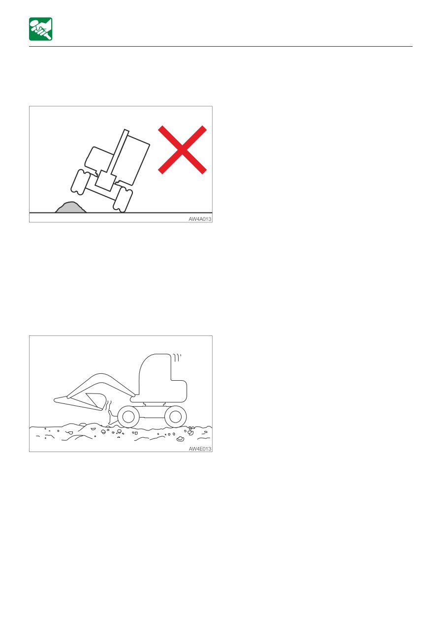
Traveling over obstacles (rocks, stumps, etc.)
may put a great load on the machine body
and may cause damage to it. Avoid crossing
over obstacles whenever possible. If you
must do so, keep the hoe attachment near
the ground, travel at a low speed, and go
over the obstacle at the center of the tires.
Precautions when traveling at high speed
• On uneven ground, maintain the low speed
and avoid starting, stopping or changing
directions abruptly.
• When traveling at high speed, do so with
the steering device set at the front.
3-22
OPERATION
OPERATING PROCEDURES
PRECAUTIONS WHEN TRAVELING ON
surface, and then take an alternative
SLOPES
path.
• The machine may slip sideways even on
a slight slope if it is covered with grass
or fallen leaves, or when traveling on
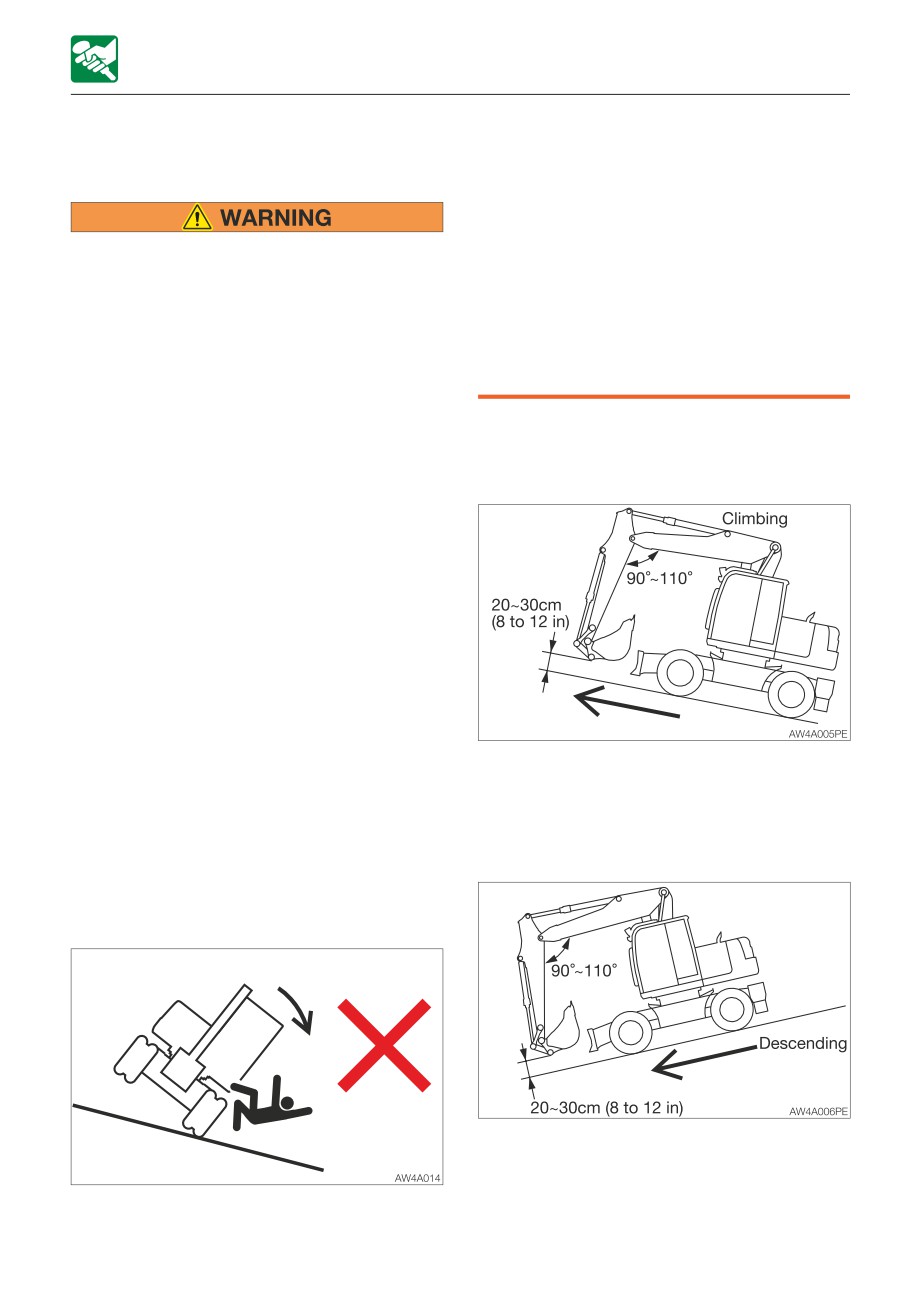
• Never travel on slopes that are too
wet meta plates or frozen surfaces. Do
steep for the machine to maintain its
not allow the machine to position
stability (maximum gradeability: 35°,
sideways to a slope.
lateral tipping angle: 15°). Note that in
• If the machine is stalled on the slope,
reality, the machine’s stability becomes
return each operating lever to the
lower than the above values depending
neutral position before restarting the
on the working condition.
engine.
• When climbing a hill, keep the
operator’s seat facing the hillside. When
descending a hill, keep the operator’s
Traveling posture on slopes
seat facing downhill. In either case,
Climbing slopes
travel must be done while paying
attention to the ground in front of the
machine.
• When traveling on slopes, lower the
bucket to a height of 20 to 30 cm (8 to
12 in.) above the ground. When climbing
a steep slope, extend the hoe
attachment to the front. In emergencies,
lower the bucket to the ground and stop
the machine.
• When traveling on slopes or grades,
travel slowly in low gear. When
descending a slope, slow down the
When climbing slopes of 15° or more,
engine speed.
maintain the machine posture as shown in
• Do not travel at speeds of over 20 km/h
the figure above.
(12.4 mph) on long down slopes.
Release the travel pedal from time to
Descending slopes
time to protect the travel motor and
ensure travel stability.
• Do not travel downhill in reverse.
When descending slopes of 15° or more,
slow down the engine speed to travel using
the low-speed travel gear and maintain the
• Do not change directions on slopes or
machine posture as shown in the figure
traverse slopes. Go down to a flat
above.
3-23
OPERATION
OPERATING PROCEDURES
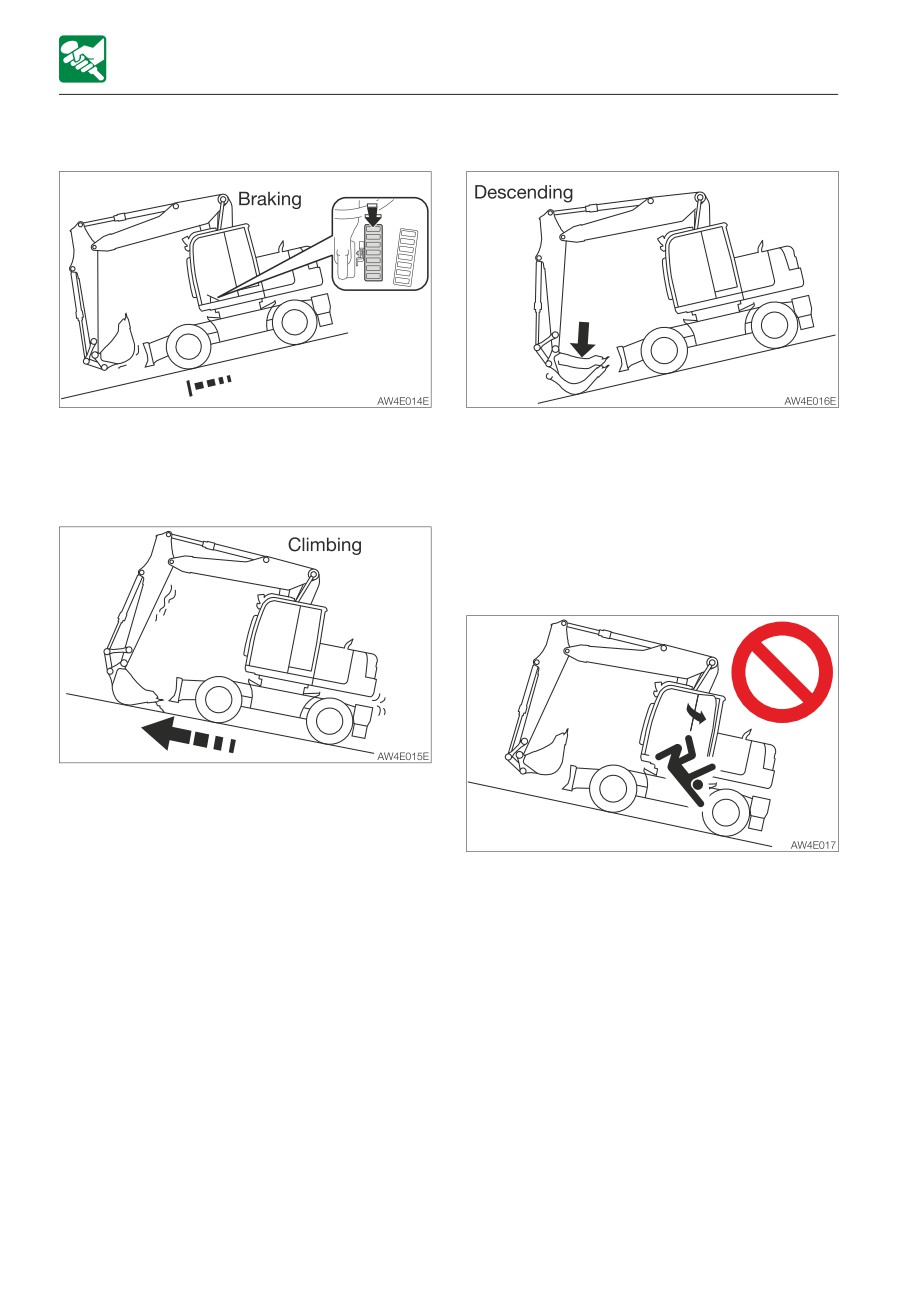
Braking when descending slopes
If the engine stops
When descending slopes, apply the brake
If the engine stops when descending a
earlier than usual.
slope, depress the brake pedal to stop the
machine, use the bucket to anchor the
If the tire slips
machine to the ground, and then start the
engine.
Do not open /close the door while
traveling on slopes
If it is impossible to climb the slope due to
tire slippage, use the pulling force of the arm
to climb the slope.
Opening/closing the door while traveling on
slopes is dangerous, as the force required to
open and close the door changes abruptly.
Always keep the door closed when traveling
on slopes.
3-24
OPERATION
OPERATING PROCEDURES
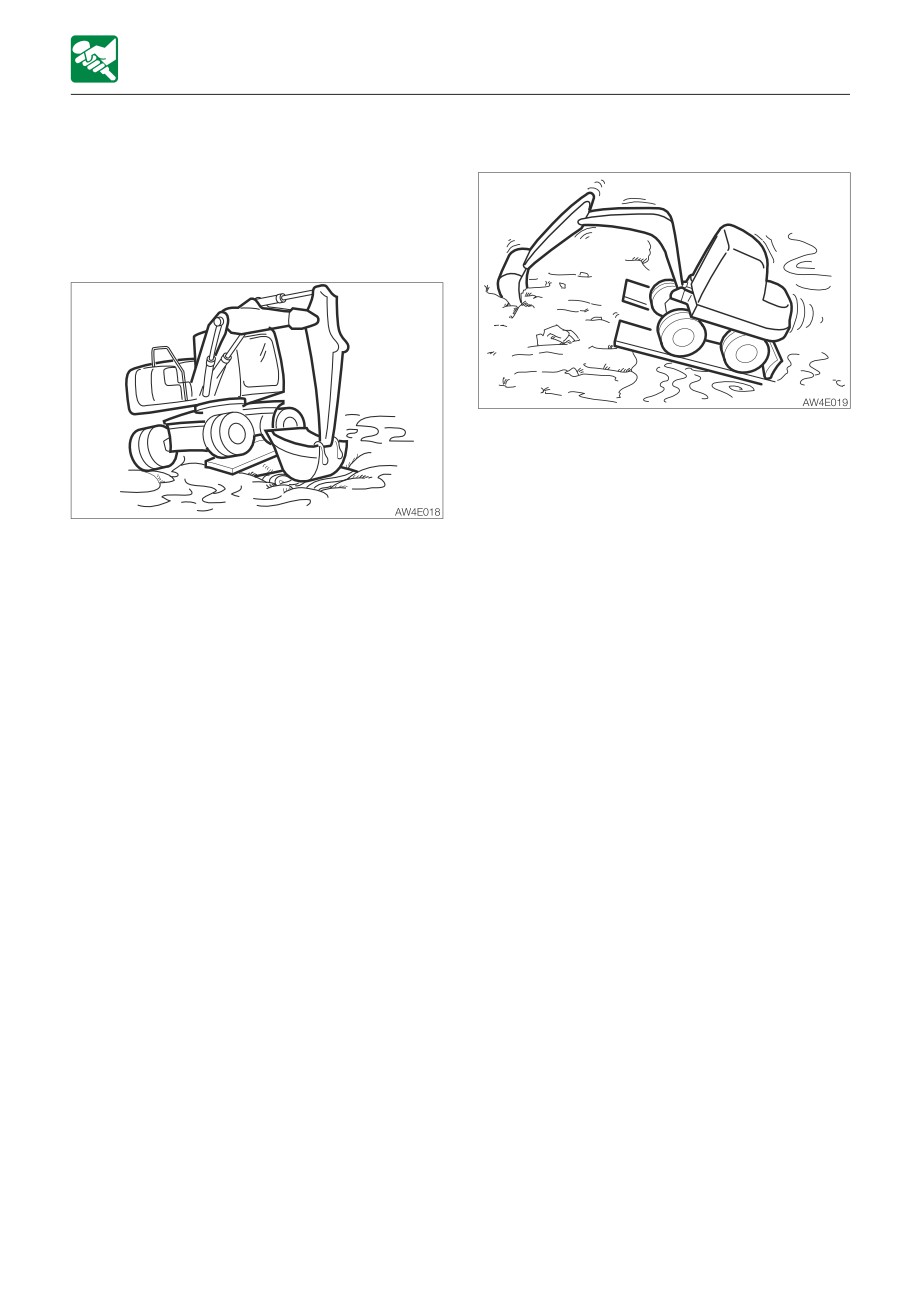
GETTING OUT OF MUD
If tires on both sides are stuck
If the machine gets stuck in mud, use the
procedure below to get it out.
If tires on one side are stuck
1. Perform the steps 1 to 4 above for both
tires.
2. Dig the bucket into the ground in front of
the machine.
3. Pull the arm while traveling forward to
1. Slew the bucket to the side of the tires
slowly move the machine out.
being stuck.
2. Set the arm and boom to an angle of 90
to 110°.
3. Press the bottom of the bucket (not the
teeth) against the ground to raise the
stuck tires.
4. Place a plank or the like under the raised
tires.
5. Lift the bucket and slowly move the
machine out of the mud.
3-25
OPERATION
OPERATING PROCEDURES
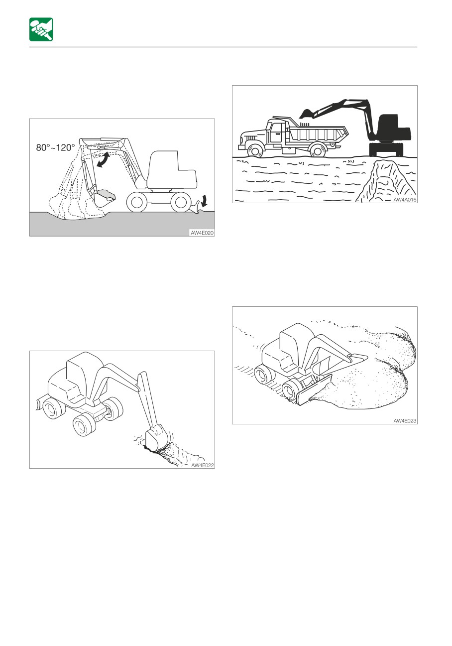
OPERATIONS POSSIBLE WITH THIS
Loading
MACHINE
Excavating
When loading dirt onto a truck bed, load
from the back of the truck, as it is easier and
able to load more load than doing it from the
1. Set the dozer blade on the side opposite
front.
to the side you want to dig on.
Also, use a small slewing angle for greater
2. Use the arm and bucket and dig with
efficiency.
shallow, long strokes. The maximum
digging force can be obtained when the
Leveling
boom and arm angle is 80 to 120°. Use
this angle for effective digging.
Digging ditches
1. Bring the hoe attachment close to the
body.
2. Gradually remove the dirt from the side of
the mound.
Install a bucket suited for digging ditches
3. Once the mound is low, remove the dirt
and set the tires parallel to the ditch to be
from the top. If the load becomes too
dug for greater efficiency.
heavy for the machine body, adjust by
When digging wide ditches, dig the sides
raising or lowering the dozer blade.
first, and then dig the center.
3-26
OPERATION
PARKING THE MACHINE
Parking procedures
PARKING THE MACHINE
1. Slowly step on the brake pedal to stop the
PARKING
machine, and then further depress the
pedal down to lock it.
2. Press the deceleration button to idle the
engine at low speed.
3. Lower the bucket and the dozer blade to
the ground.
When replacing the attachment or
performing the inspection and
maintenance on it, follow the procedure
“Releasing the residual pressure from the
working equipment circuit” described
below, as necessary.
4. Raise the safety lock lever to the lock
position.
5. Stop the engine and remove the starter
• Park the machine on a flat, rigid and
key.
safe ground. Set the parking brake,
Refer to “Stopping the engine” on page
brake pedal lock and wheel stoppers.
3-5.
6. Lock the cab, fuel filler cap and covers,
take the key with you and store it in a
specified place.
Releasing the residual pressure from the
working equipment circuit
Perform the operation of releasing the
residual pressure within 10 minutes after the
engine comes to a complete stop.
1. Stop the engine.
2. Turn the starter switch to the ON position.
3. Lower the safety lock lever to the unlock
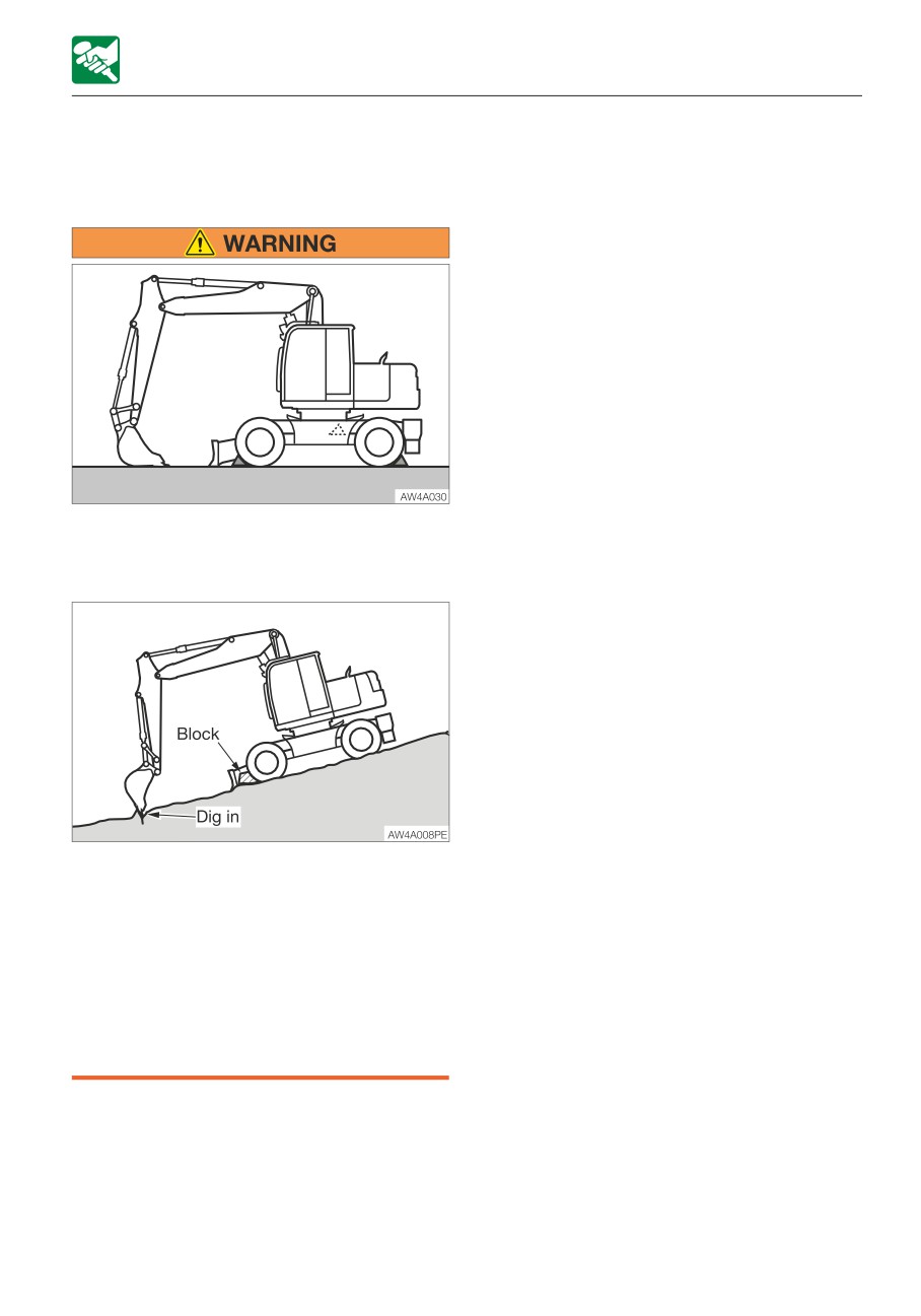
If you must park on a slope, chock the
position.
wheels to block the machine.
4. Release the lock of the attachment lock
• When parking on a street, use barriers,
button.
caution signs, lights, etc., so that the
5. Move all the control levers, pedals and
machine can easily be seen even at
auxiliary hydraulic switches several times
night to avoid collision with other
in all directions to release the residual
vehicles.
pressure in the working equipment circuit.
• Before leaving the operator’s seat,
safely park the machine by referring to
“Parking procedures” below.
3-27
OPERATION
PARKING THE MACHINE
INSPECTION AND CHECKS AFTER
STOPPING THE ENGINE
1. Check for oil or water leak and inspect the
working equipment, covers and
undercarriage. If any irregularities are
found, repair.
2. Fill up the fuel tank.
Refer to “Inspecting the fuel level” on page
5-23.
3. Remove any paper scraps or dirt from the
engine room.
4. Remove any mud from the undercarriage.
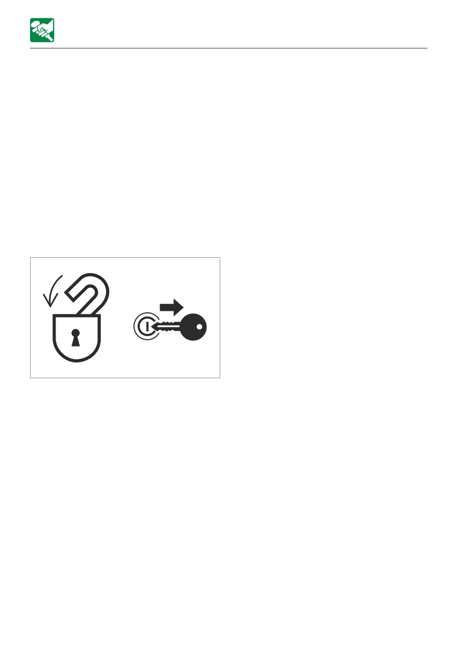
Locking
Be sure to lock the following places:
AG7A009
• Fuel filler cap
• Cab door
• Covers
3-28
OPERATION
HANDLING IN COLD CLIMATES
CAUTIONS AFTER OPERATIONS
HANDLING IN COLD
Observe the following cautions to prevent
CLIMATES
mud, water, or the undercarriage from
PREPARING FOR COLD CLIMATES
freezing and making it impossible for the
machine to move.
Starting engine in cold climates is not easy,
• Remove all mud and water from the
and it becomes more difficult if the coolant
machine body. In particular, wipe the
freezes. Prepare for cold-climate problems
hydraulic cylinder rod clean to prevent
as follows.
damage to the seal caused by mud or dirt
on the rod surface getting inside the seal
Replacing the fuel and lubricant
together with drops of water.
Replace the hydraulic oil, engine oil and fuel
• Park the machine on hard and dry ground.
with those intended for cold climates.
If this is impossible, park the machine on a
Refer to “Fuel and lubricant table” on page
wooden board placed on ground.
5-4.
• Drain any water in the fuel tank to prevent it
from freezing.
Engine coolant
Refer to “Draining the water from the fuel
tank” on page 5-35.
• As the battery capacity drops markedly in
The engine coolant is combustible. Keep
low temperatures, cover the battery or
away from flame.
remove it from the machine and keep it in a
Use long-life coolant (antifreeze) and tap
warm place.
water for the engine coolant.
If the electrolyte level is low, add distilled
water in the morning before beginning
Note: New machines are delivered with JIS
work. To prevent the battery electrolyte
Type 2 long-life coolant (antifreeze) at a
from freezing in the night, do not add water
concentration of 50%.
after the day’s work.
Refer to “Fuel and lubricant table” on page
5-4.
AFTER THE COLD CLIMATE
Battery
As the temperature drops, the battery
When the climate becomes warmer, do as
performance decreases.
follows:
Inspect the battery. If it is discharging,
• Replace the fuel and oil for all parts with
contact a Takeuchi service agent to have the
those specified in the “Fuel and lubricant
battery recharged.
table”.
Refer to “Inspecting the battery fluid level
Refer to “Fuel and lubricant table” on page
and replenishing” on page 5-36.
5-4.
• If a coolant of “one season type” is used,
drain the cooling system completely, clean
out the inside of the cooling system
thoroughly, and fill with tap water.
Refer to “Cleaning the engine cooling
system” on page 5-57.
3-29
OPERATION
HANDLING TIRES
HANDLING TIRES
Tires are weak in strength due to the material
they are made of. Be sure to observe the
prohibitions and precautions below to
prevent the tires from being damaged or
coming off.
PROHIBITIONS
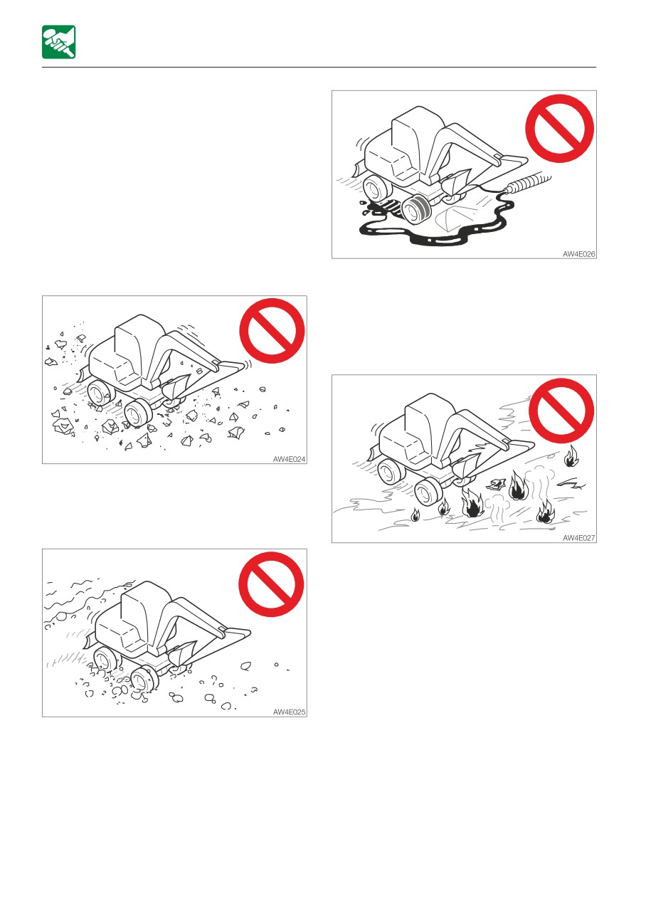
Do not travel or operate the machine in the
following places:
• Do not let fuel, oil, salt or chemical solvents
get on the tires. These substances may
corrode the metal wheels and tires,
resulting in rust or peeling. If you find any of
these on the tire, immediately wipe if off
and clean the tire with water.
• Traveling or slewing on crushed rock,
extremely rough hard rock, steel beams,
scrap iron or near the edges of steel plates
will cause damage to the tires.
• The treads will show irregular wear or will
be damaged, if the machine travels on
recently paved asphalt road, ground
around a bonfire or hot iron sheets under
the blazing sun.
• Do not move earth in places where the
tires may slip. Doing so may speed up
tread wear.
• Traveling on riverbeds or places where
there are many boulders may cause the
stones to get caught and damage the tires
or make the tires come off.
• Do not use the machine on the seashore.
The salt may corrode the metal wheels.
3-30
OPERATION
HANDLING TIRES
PRECAUTIONS
Observe the following precautions when
operating the machine:
• Tires are not very stable. Be very careful
when slewing sideways.
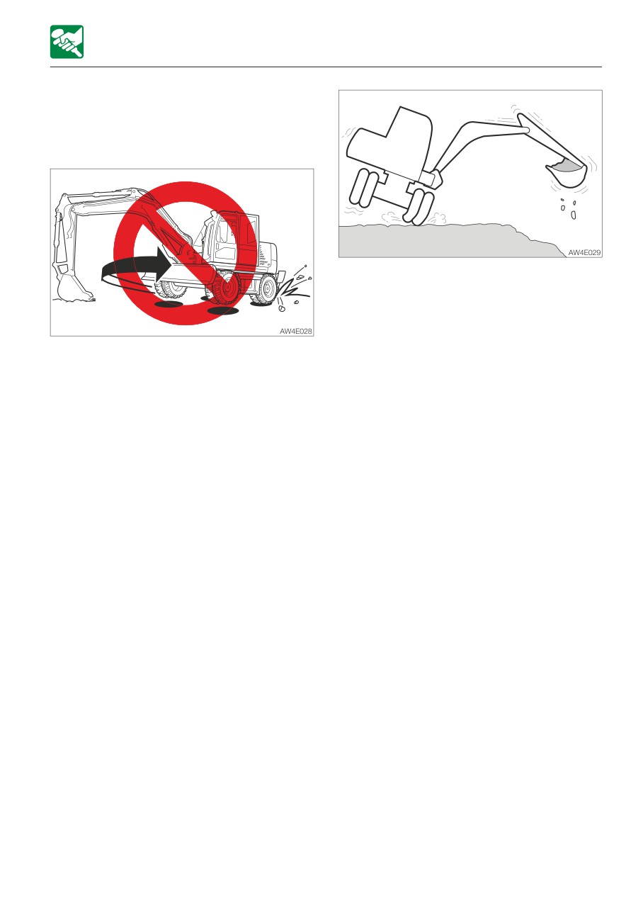
• Do not turn the undercarriage with the front
of the machine body lifted using the hoe
attachment (the upperstructure is not
turned). Doing so will twist the tires with the
load concentrated on a single point on the
tire, causing rapid damage to the tires.
• Avoid changing courses abruptly whenever
possible. Doing so may wear or damage
the tires.
• Avoid falling of the machine that may
expose the tires to strong shocks.
• Salt, potassium chloride, ammonium
sulfate, potassium sulfate and triple
superphosphate can damage the tires. If
any of these substances gets on the tires,
wash if off thoroughly with water.
• Do not let the sides of the tires rub against
concrete or walls.
• Do not let the bucket hit the tires and
damage them.
• Be especially careful on snowy or frozen
surfaces in winter, as the tires easily slip in
such conditions.
• Use tires at temperatures between -25°C
to +55°C (-14°F to 131°F).
• When storing the tires for long periods of
time (three months or more), do so indoors
in a place not exposed to direct sunlight or
rain.
3-31
3-32
TRANSPORT
4-1
TRANSPORT
LOADING AND UNLOADING
LOADING AND UNLOADING
The machine may roll or tip over or fall
while being loaded or unloaded. Take the
following precautions:
• Select a firm, level surface and keep
sufficient distance from road shoulders.
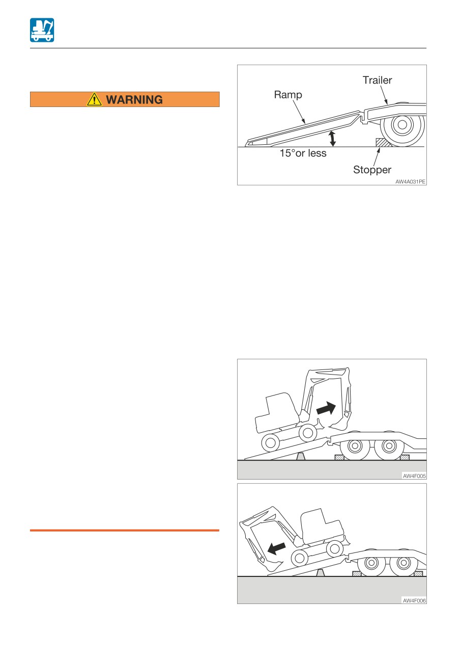
• Secure ramps of adequate strength and
size to the truck bed. The slope of the
ramps must not exceed 15°.
1. Set the parking brake on the transporter
• Never use the working equipment to
and chock the wheels.
load or unload the machine. Doing so
2. Fix the ramps securely to the truck bed.
may result in tipping over or falling
The slope of the ramps must not exceed
down of the machine.
15°.
• Keep the truck bed and loading ramps
3. Align the center of the truck bed with the
clean of oil, soil, ice, snow and other
center of the machine, and of the ramp
materials to prevent the machine from
with the center of the tires.
sliding sideways. Clean the tires too.
4. Make sure the dozer blade does not hit
• Chock the transporter wheels to prevent
the ramps.
movement.
5. Lower the hoe attachment as far as
• When traveling on the uneven road or
possible without letting it touch the
sharp slope, turn off the deceleration
transporter.
switch and the auto-deceleration
6. Decrease the engine speed.
switch. If the machine is operated on
such roads with these switches turned
on, the engine speed may increase,
causing the machine to travel
unexpectedly rapidly (for machines with
the deceleration and auto-deceleration
switches).
• When being loaded or unloaded, travel
slowly in low gear by following the
signal from the signal person.
• Never change courses on the ramp.
• Do not slew on the ramp. The machine
may tip over.
• When slewing on the truck bed, do it
slowly as the footing should be
unstable.
When loading or unloading the machine, be
sure to use ramps or a platform and follow
the procedure below.
4-2