Takeuchi Hydraulic excavator TB1160W (Serial No. 514500002~). Operator's Manual (2016) - page 3
CONTROLS
MULTI-INFORMATION DISPLAY
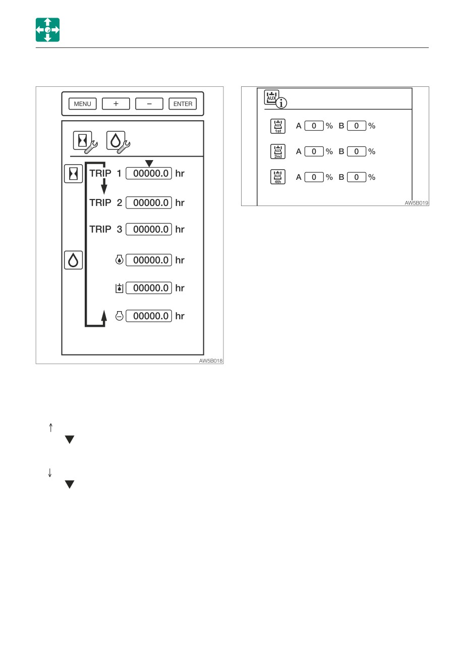
(1) TRIP METER SETTING
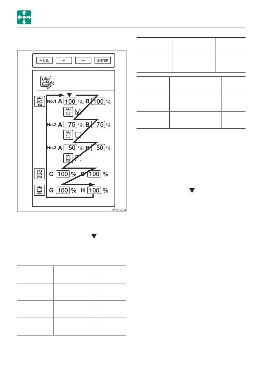
(2) AUXILIARY LINE FLOW RATE DISPLAY
Displays the output information of the
Auxiliary 1st, 2nd and 4th.
The flow rate cannot be changed.
Six patterns of desired operating hours can
be set.
To start setting, press the Enter key. The
value flashes while being set.
+ (
) key: Increases the value or moves the
cursor upward. Rapidly increases the
value when pressed and held for one
second.
- (
) key: Decreases the value or moves the
cursor downward. Rapidly decreases the
value when pressed and held for one
second.
Enter key: Confirms setting
Menu key: Cancels setting or returns to the
Menu screen.
Pressing and holding the Enter key for three
seconds clears the trip meter pointed by the
cursor.
2-29
CONTROLS
MULTI-INFORMATION DISPLAY
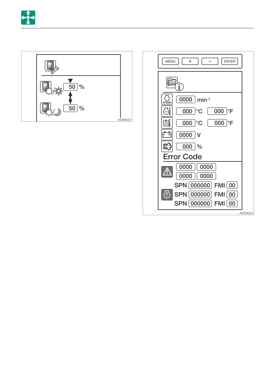
(3) AUXILIARY LINE FLOW RATE SETTING
Maximum
A/B common,
Variable
flow rate
high-flow
range
Auxiliary
200%=224L/min
100 to
1st-1, 2, 3
(59.2 US gpm)
200%
Initial
Variable
Standard flow
condition
range
C/D 100%=112L/
10 to
Auxiliary 2nd
min (29.6 US gpm)
100%
G/H 100%=112L/
10 to
Auxiliary 4th
min (29.6 US gpm)
100%
The table shows the 1-way flow rate when
there is no load.
Pressing the minus (-) key will move the
cursor in the direction of the arrow.
Pressing the plus (+) key will move the cursor
in the opposite direction of the arrow.
To edit the setting, press the Enter key at the
position of the cursor . The value display
keeps flashing during editing.
Set the flow ratio to the desired level, and
then press the Enter key to confirm. The
Three flow rate patterns can be set in the
value display stops flashing.
auxiliary 1st.
Keep increasing the flow ratio to set to
Refer to the trip meter setting for the key
“high-flow” with the checkmark (√) on the
operation. To move the cursor in the
right of the flow symbol. The symbol of the
direction of the arrow, use the minus (-) key.
selected flow rate setting will appear at the
To move the cursor in the opposite direction
lower left of the Main screen.
of the arrow, use the plus (+) key.
One pattern of the auxiliary 2nd /4th flow rate
can be set.
Initial
A/B common,
Variable
condition
standard flow
range
100%=112L/min
Auxiliary 1st-1
10 to 100%
(29.6 US gpm)
75%=84L/min
Auxiliary 1st-2
10 to 100%
(22.2 US gpm)
50%=56L/min
Auxiliary 1st-3
10 to 100%
(14.8 US gpm)
2-30
CONTROLS
MULTI-INFORMATION DISPLAY
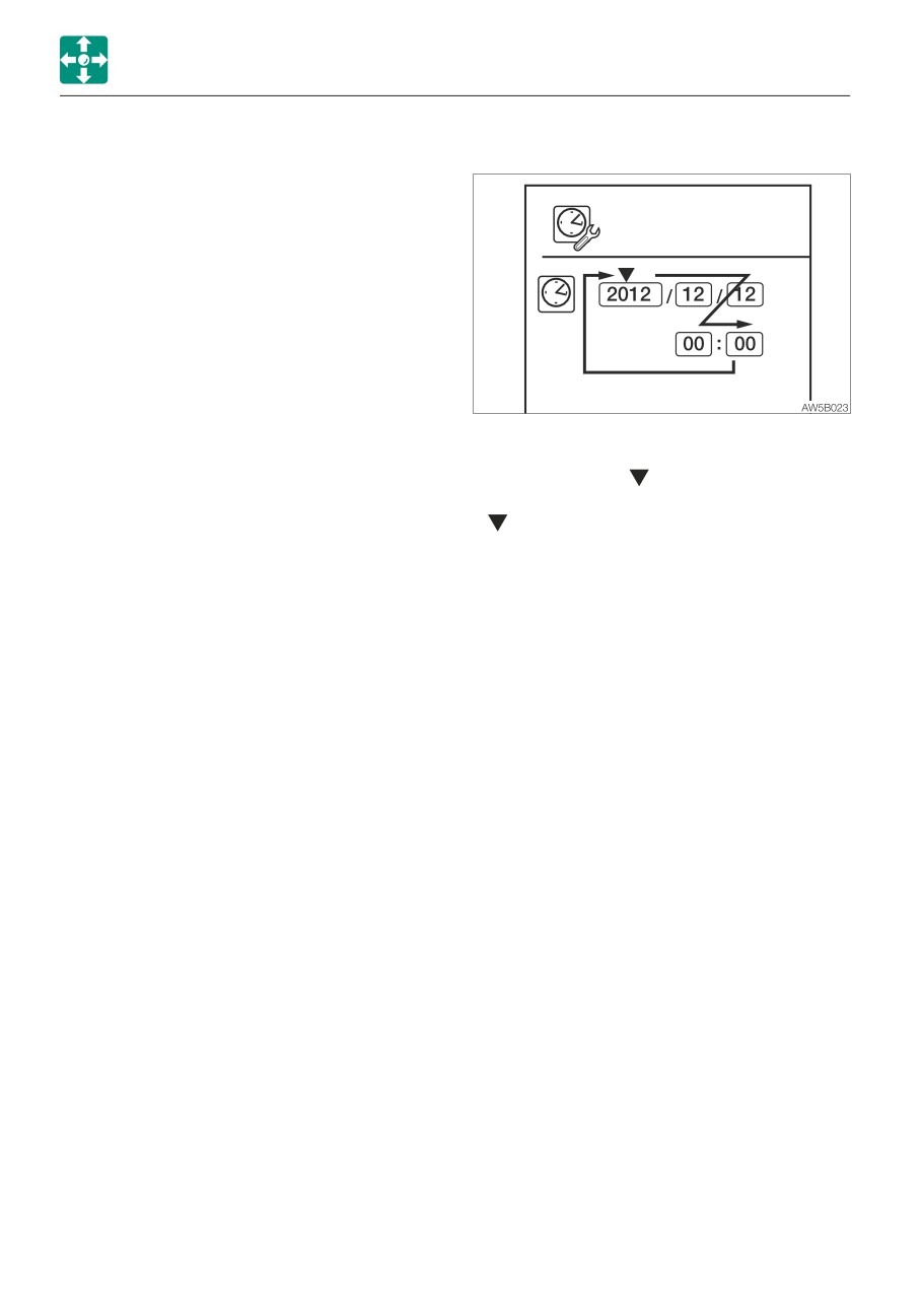
(4) LCD SETTING
(5) DATA /ERROR CODE DISPLAY
• The brightness of the LCD is set to
between 0 and 100%. The brightness
changes each time the adjustment is
made.
Day mode: initial setting value is 50%
Night mode: initial setting value is 50%
While in the day (night) mode, adjustment
is possible only for the brightness set to the
night (day) mode.
Refer to the trip meter setting for the key
operation.
Displays various data and error codes. The
setting cannot be changed.
Display items
• Engine RPM
• Coolant temperature
• Hydraulic oil temperature
• Battery voltage
• PM accumulation amount
2-31
CONTROLS
MULTI-INFORMATION DISPLAY
Error code display
(6) DATE AND TIME SETTING
• Vehicle error code
Displays four error codes, with the latest
code in the upper left.
Refer to “Vehicle error code list” on page
6-14 to 6-15.
• ECM error code
Engine ECM (Engine Control Module) error
code
Displays three error codes, with the latest
code at the top.
Refer to “Engine error code list” on pages
6-16 to 6-19.
The year, month, date, hour and minute can
be set. (Effective year range: 2010 to 2099)
IMPORTANT: If an error code appears,
• Move the cursor to the clock symbol,
immediately stop the operation and
and then press the Enter key. The cursor
contact a Takeuchi sales or service outlet
will be shifted to the place for setting the
for help.
year.
Press the Enter key again, and then enter
the year. (The year display keeps flashing
during editing.)
Press the Enter key to confirm. The month,
date, hour and minute can be set using the
same procedure for the year.
Refer to the trip meter setting for the key
operation.
2-32
CONTROLS
MULTI-INFORMATION DISPLAY
SWITCHING IMAGES
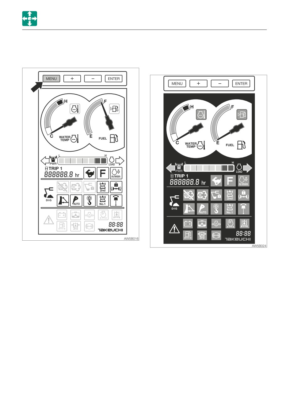
• Background color (daytime)
• Changing the background color (day /
night)
When one of the items (head light, signal
light, working light, high beam switch) is
turned on, the background will always be
night mode in any screen even if the display
brightness is lowered.
2-33
CONTROLS
MULTI-INFORMATION DISPLAY
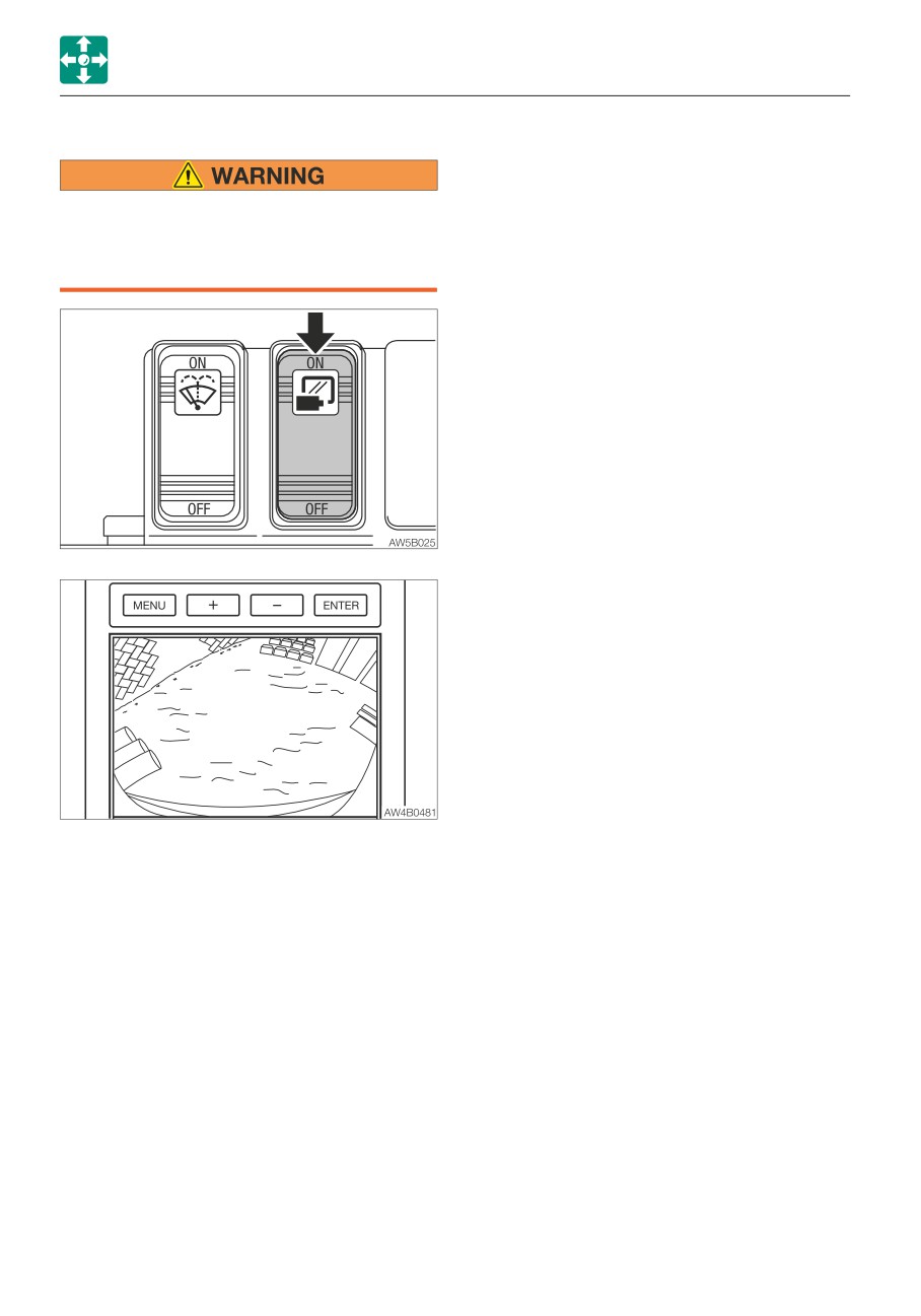
• CAMERA
Do not look at the images produced by
the camera while traveling in reverse.
Move in reverse while looking at the
direction of travel.
1. Press the ON (symbol) side of the image
select switch (CAMERA) to show the
camera image captured by the external
camera at the top of the screen.
2. Press the OFF side of the switch to return
to the Main screen from the camera
screen.
2-34
CONTROLS
CONTROL CONSOLE
CONTROL CONSOLE
SWITCHES
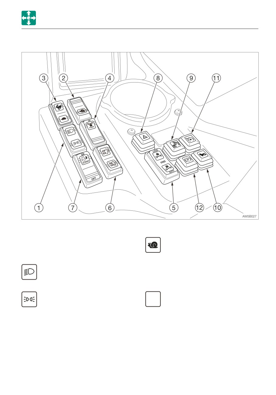
2. Creeping travel switch
Pressing this switch displays the
1. Light switch
digging mode.
When this switch is depressed, the lights are
Depress the “Snail” symbol on this
illuminated as follows.
switch to change the travel speed to
creeping travel.
..........Headlights, Position lamps
· Stop the machine before switching the
travel gear.
Neutral
OFF
Depress the other side of the switch
..........Position lamps
to change to the high/low-speed
travel gear.
Note: This switch can be operated even
when the power is turned off.
2-35
CONTROLS
CONTROL CONSOLE
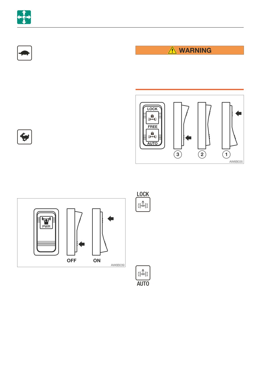
3. Low /high-speed travel switch
5. Ram Lock switch
Low-speed travel
Depress the “Turtle” symbol on this
switch to change the travel gear from
Do not lock the suspension while
high-speed travel to low-speed travel.
traveling. Doing so may create a
It is possible to switch from the low-speed
dangerous situation. Be sure to lock the
travel “Turtle” to the high-speed travel “Hare”
suspension only when working with the
while traveling. However, switching from the
machine.
high-speed travel to low-speed travel must
be done after stopping the machine,
because it could cause an abrupt stopping
or overspeeding, resulting in damage to the
devices.
High-speed travel
Depress the “Hare” symbol on this
switch to change to the high-speed
travel gear.
Note: If the creeping travel switch has been
depressed, the creeping travel switch takes
Lock the suspension of the front axle
a higher priority.
(wobbling) with this switch to prevent the
cylinder from moving.
4. Power mode switch
Locks the suspension of the front
axle.
Push the LOCK side of the switch
to secure the machine when
working.
FREE
Unlocks the suspension. Keep the
switch in this neutral position
while traveling (High-speed travel:
Low-speed travel switch is off).
While in the traveling mode, the powe mode
The suspension is automatically
is always used.
locked if the brake is pressed
• Pressing the PWR symbol side of the
when traveling at low speed
switch turns on the Power mode indicator
(low-speed travel: turtle symbol),
lamp on the Multi-information display.
and it is unlocked when the brake
The maximum engine output is obtained.
is released.
• STD mode: Pressing the blank side of the
When traveling at high speed
switch will turn off the power mode
(high-speed travel: low-speed
indicator lamp.
travel switch is off), the
Refer to “Multi-information display” on
suspension is not locked even if
page 2-16.
the brake is pressed.
2-36
CONTROLS
CONTROL CONSOLE
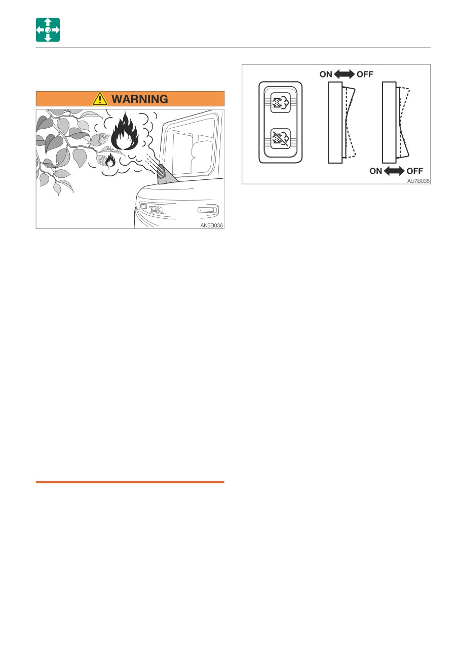
6. DPD manual regeneration /inhibit select
switch
IMPORTANT: Press the manual
regeneration side on the DPD manual
regeneration/inhibit select switch to burn
the particulate matter (PM), when the
• The DPD and the exhaust gas emitted
DPD manual regeneration lamp flashes
from the exhaust line can be very hot
and an alarm sounds. If the machine
while the engine is running or the
continues to be operated without
regeneration is under way, as well as
performing the manual regeneration, the
immediately after the engine is stopped.
engine power will decrease and
Be careful not to accidentally touch
eventually the engine will stop running.
them; doing so could cause burns.
The ECM warning display will also flash if
• Do not perform the DPD regeneration if
the DPD needs to be repaired. A number
the machine is surrounded by
appears on the engine error code screen.
flammable items such as plants, trees,
Refer to the “Engine error code list” and
dry grass, wastepaper, oil and waste
contact a Takeuchi sales or service dealer
tires. There is a risk of fire due to the
for repair.
high-temperature exhaust gas emitted
from the DPD.
• DPD manual regeneration
• Do not perform the DPD regeneration in
When the DPD manual regeneration
poorly-ventilated indoor spaces, as
symbol on the display starts flashing and
smoke may be generated during the
an alarm starts sounding, perform the DPD
regeneration.
manual regeneration by following the
• Do not perform regeneration when the
procedure below.
engine hood is open. There is a risk of
1. Park the machine in a safe place where
fire due to the high-temperature exhaust
there is no fire hazard.
gas emitted from the DPD.
2. Raise the safety lock lever to the lock
position.
· Do not lower the safety lock lever and
move the control levers during
regeneration. Doing so interrupts the
regeneration.
3. Decrease the engine speed to low idling.
4. Press and hold the manual regeneration
side on the DPD manual regeneration/
inhibit select switch.
2-37
CONTROLS
CONTROL CONSOLE
·
Since the DPD regeneration is designed to
work only when the accumulated
particulate matter (PM) in the filter exceeds
a certain amount, it will not start otherwise,
even if you attempt to perform manual
regeneration.
• DPD regeneration inhibit (cancel)
To cancel the DPD regeneration currently
being processed (manual or auto), press
the regeneration inhibit symbol side.
5. The manual regeneration symbol stops
The DPD regeneration inhibit symbol
flashing and remains lit to indicate that
appears on the display, and the
the engine RPM is automatically
regeneration operation must be performed
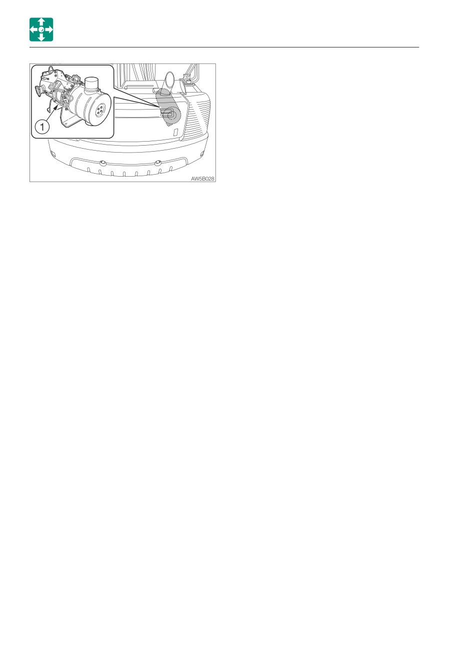
increased and the DPD (1) regeneration
again. Start the manual regeneration
(PM burning) has started.
procedure from Step (1) above, as soon as
6. Release the switch. Do not leave the
possible. Do not press the DPD
machine during regeneration.
regeneration inhibit switch unless there is a
It takes approximately 15 to 20 minutes,
risk of fire.
depending on the ambient temperature,
To cancel, press the switch again. Turning
to complete the regeneration operation.
the starter switch to OFF will also cancel
7. The manual regeneration symbol goes
the operation.
off to indicate the end of manual
Refer to “DPD manual regeneration/
regeneration.
regeneration inhibit /auto regeneration
display” on page 2-20 and 2-21.
Note:
· Do not lower the safety lock lever and
move the control levers during
regeneration. Doing so interrupts the
regeneration.
· In some cases smoke may be emitted from
the tail pipe while the DPD regeneration is
being performed. This is not a failure; it is
due to burning of the particulate matter
(PM).
· In some cases the noise associated with
the DPD regeneration operation or cancel
operation may change; this is not a failure.
· The DPD manual regeneration can be
completed faster while the machine engine
is warm rather than cold. Note that the
manual regeneration does not start unless
the coolant temperature is higher than a
set value. The coolant temperature may
increase while manual regeneration is being
performed.
2-38
CONTROLS
CONTROL CONSOLE
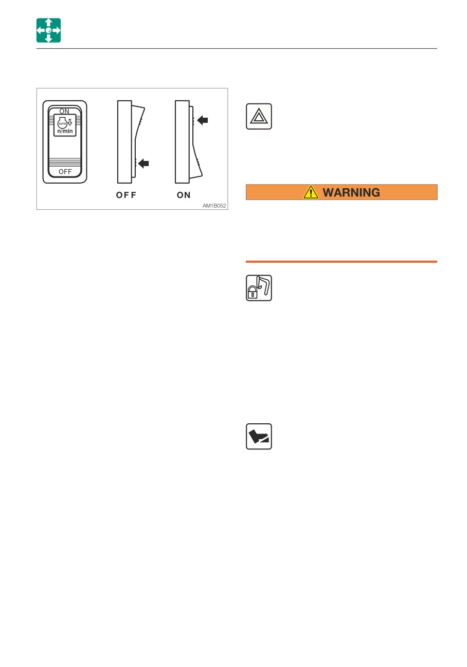
7. Automatic deceleration switch
BUTTONS
8. Hazard button
Press this button to turn on the
hazard lamp. The turn signal indicator
lamp also turns on.
Note: This switch can be operated even
when the power is turned off.
9. Attachment lock button
When traveling on a road, be sure to lock
When the ON side of the switch is pressed,
the working equipment. If any of the
the deceleration lamp in the Multi-information
controls is accidentally touched when it is
display flashes. This flashing stops when the
unlocked, the machine may suddenly
deceleration function starts working, and the
move and cause serious injury or death.
lamp remains lit while in the deceleration
mode. The engine speed automatically drops
This button is used when traveling on
to low idle (deceleration mode) four seconds
a road. Pressing this button will turn
after the control levers are set to neutral, to
on the button lamp, indicating that
reduce fuel consumption. Moving the control
the operations of the hoe attachment,
levers will cause the speed to return to the
slewing, auxiliary circuit and blade
original engine speed.
(outriggers) are locked. The attachment lock
Switching from the deceleration button to the
indicator lamp lights up on the display.
auto-deceleration switch will first return to
Pressing this button again will turn off the
the engine speed set with the throttle
lamp and the indicator lamp, indicating that
controller. Then, the engine will automatically
the locking is released.
enter the deceleration mode (low idling) if the
control levers are not operated within four
10. Travel pedal button (foot accelerator
seconds.
mode)
Pressing this button while the brake
pedal is depressed will turn on the
button lamp, indicating that the
engine RPM can be controlled by operating
the travel pedal. The travel pedal indicator
lamp lights up on the display. Turn on this
switch when traveling. This button can be
used in the digging mode.
Pressing this button again will turn off the
lamp and the indicator lamp, indicating that
the foot accelerator mode is canceled.
2-39
CONTROLS
CONTROL CONSOLE
11. Auto-cruise button (cruise control)
12. Parking brake button
Pressing this button will turn on the
button lamp, indicating that the
Do not use this button on the following
parking brake is engaged. The
roads.
parking brake indicator lamp lights up on the
• Heavy traffic roads where a safe
display.
spacing between vehicles cannot be
Pressing this button again will turn off the
kept.
lamp and the indicator lamp, indicating that
• Roads with many steep down slopes or
the parking brake is disengaged. (When the
curves.
safety lock lever is fully lowered to the
• Slippery roads due to freezing or
unlocked position while the engine is
snowing.
running.)
Note: When traveling the slopes (up or
IMPORTANT: Do not activate the parking
down), a constant vehicle speed cannot be
brake while digging. Doing so could
retained due to the gradient.
damage the brake disk due to the
excessive load acting on it. Lock the
The cruise control (automatic
brake pedal by depressing it down.
constant speed traveling device) is a
Note: The parking brake is automatically
feature that enables to retain a
activated when the power is turned off.
desired vehicle speed without operating the
travel pedal.
This function is available in the low-speed
travel (Turtle) mode or in the high-speed
travel (Hare) mode. Note that it only applies
to the “forward” traveling.
Setting a speed
1. Fully depress the travel pedal.
2. Press the auto-cruise button to set to the
maximum speed. The cruise indicator
lamp lights up on the display, and the
auto-cruise button lamp also lights up.
The travel speed can be adjusted by
increasing or decreasing the engine RPM
(throttle control).
Canceling the speed setting
To cancel, do either of the following. The
auto-cruise display lamp will also go out.
• Step on the brake pedal.
• Step on the travel pedal.
• Press this button again. The button lamp
will also go out.
2-40
CONTROLS
SWITCHES
ENGINE SHUTDOWN SWITCH
SWITCHES
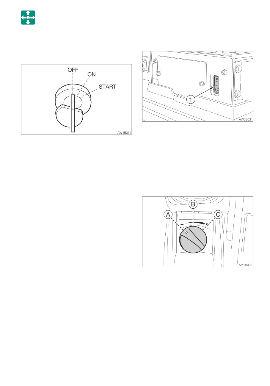
STARTER SWITCH
This switch is used to shutdown the engine if
it fails to stop, due to machine failure or
IMPORTANT: Do not repeatedly switch
breakage, when the starter switch is set to
the key from OFF to ON and ON to OFF
the OFF position.
over a short period. Doing so will cause
1. Press the switch (1).
engine breakdown.
2. After use, return the switch (1) to the
original position.
OFF
Position for stopping the engine
and inserting or removing the key.
ON
Position in which the engine is
THROTTLE CONTROLLER
running. At this position, all the
electrical equipment is functional.
When the coolant temperature is
too low, the engine is
automatically preheated.
START Position for starting the engine.
When the key is released, the
switch automatically returns to the
ON position.
This controls the engine speed.
(A) Low idling
(B) Medium speed
(C) Maximum speed
Note: The engine RPM can only be
decreased up to “1250” with the throttle
controller.
2-41
CONTROLS
SWITCHES
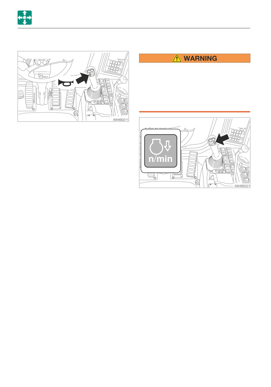
HORN BUTTON
DECELERATION BUTTON
Before operating the deceleration button,
set the operating lever to the neutral
position and take your foot off the pedals.
If the deceleration button is pressed while
driving, the machine’s operating speed
will abruptly change to result in a
dangerous situation.
Press the button situated on the right
operating lever to blow the horn.
Press this button on the right operating lever
to lower the engine speed to low idling.
Press the button again to return to the
engine speed set with the throttle controller.
For safety reasons, it is designed that the
deceleration function is activated to set the
engine revolutions to low idling whenever the
engine is started.
Cancel the deceleration mode by pressing
the deceleration button as necessary.
Note: This deceleration button is capable of
decreasing the engine speed and reducing
the fuel consumption, with a simple
operation, in a situation such as when little
engine output is required and thus the
operating or the travel levers are in neutral.
2-42
CONTROLS
SWITCHES
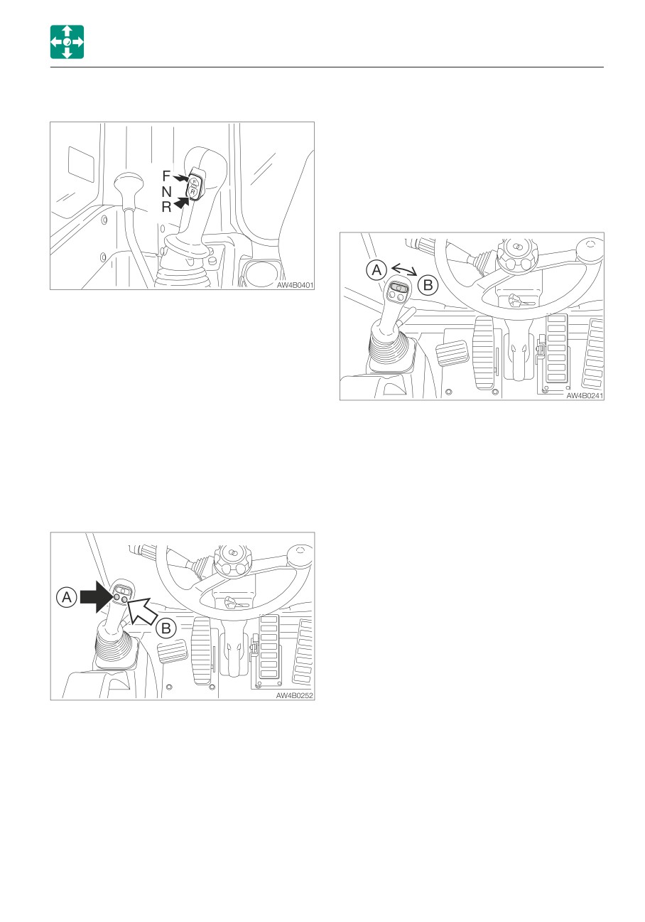
TRAVEL SELECT BUTTON
Slider switch
(Proportional control)
Proportional control allows for slow-to-fast/
fast-to-slow movement of attachment.
Example: If you move the slider switch half
way, the attachment will move at
approximately one-half the speed.
Use this button to change the travel
direction.
Step on the brake pedal when the machine
is stopped, and then shift the gear.
F
Forward
N
Neutral
R
Reverse (reverse light is lit)
For actual operation, step on the travel pedal
Move this switch to control the flow of the oil
for traveling.
in the first auxiliary hydraulic lines.
(A)
Hydraulic oil flows to the left auxiliary
line (a).
FIRST AUXILIARY HYDRAULIC SWITCHES
(B)
Hydraulic oil flows to the right auxiliary
line (b).
Auxiliary hydraulic buttons
Refer to “Auxiliary hydraulic lines” on page
2-65 to 2-69.
Press those buttons to control the flow of the
oil in the first auxiliary hydraulic lines.
• Proportional control of the auxiliary
hydraulic circuit is not possible.
(A)
Hydraulic oil flows to the left auxiliary
line (a).
(B)
Hydraulic oil flows to the right auxiliary
line (b).
2-43
CONTROLS
SWITCHES
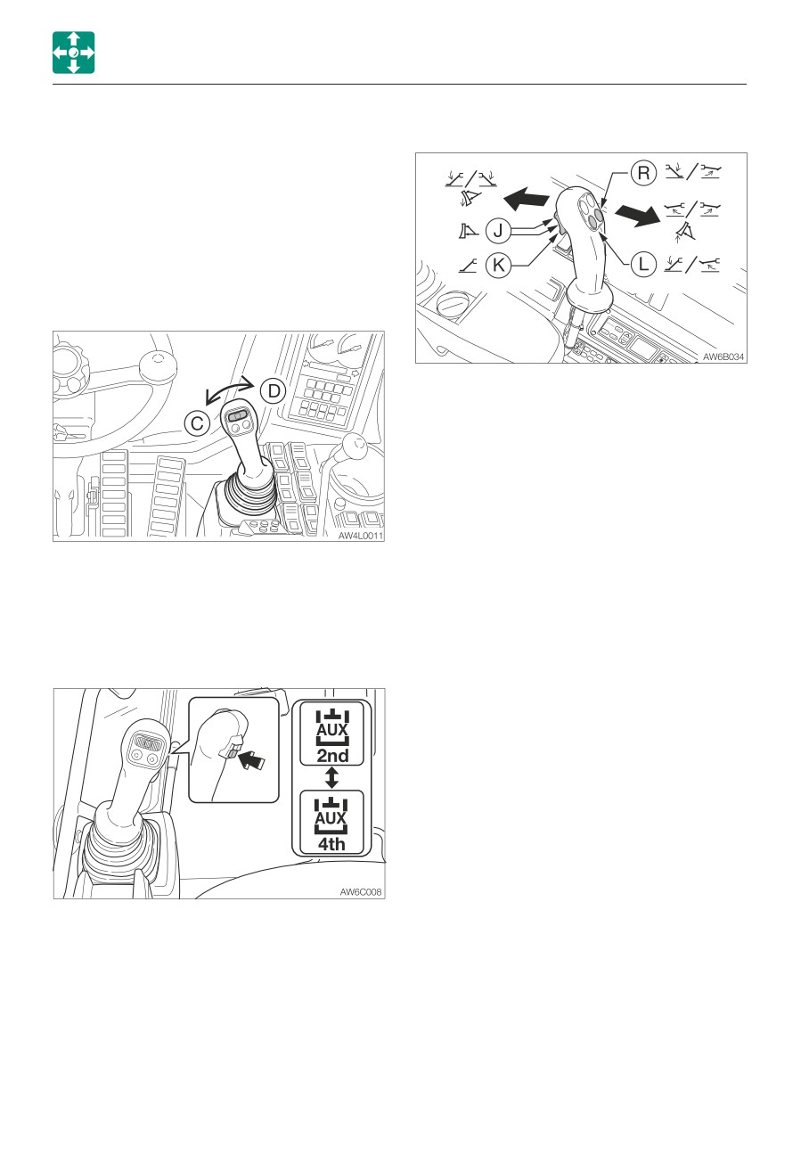
SECOND /FOURTH AUXILIARY
OUTRIGGER SWITCHES (IF EQUIPPED)
HYDRAULIC SWITCH
Slider switch
(Proportional control)
Proportional control allows for slow-to-fast/
fast-to-slow movement of attachment.
Example: If you move the slider switch half
way, the attachment will move at
approximately one-half the speed.
J
Dozer blade operation (both sides)
K
Outrigger operation (both sides)
L
Left outrigger operation
R
Right outrigger operation
The outrigger operation is performed with the
blade /outrigger lever.
Move this switch to control the flow of the oil
THIRD AUXILIARY HYDRAULIC SWITCH
in the second auxiliary hydraulic lines.
AND BUTTON
(C):
Hydraulic oil flows to the left auxiliary
line (c).
Refer to “Third auxiliary hydraulic switch and
(D):
Hydraulic oil flows to the right auxiliary
button” on page 2-68.
line (d).
AUX. 2/4 SELECT BUTTON
Refer to “Aux. 2/4 select button (If equipped)”
on page 2-69.
To use the fourth auxiliary hydraulic, press
the Aux. 2/4 select button to change the line
to the fourth auxiliary hydraulic.
Refer to “Auxiliary hydraulic lines” on page
2-65 to 2-69.
2-44
CONTROLS
SWITCHES
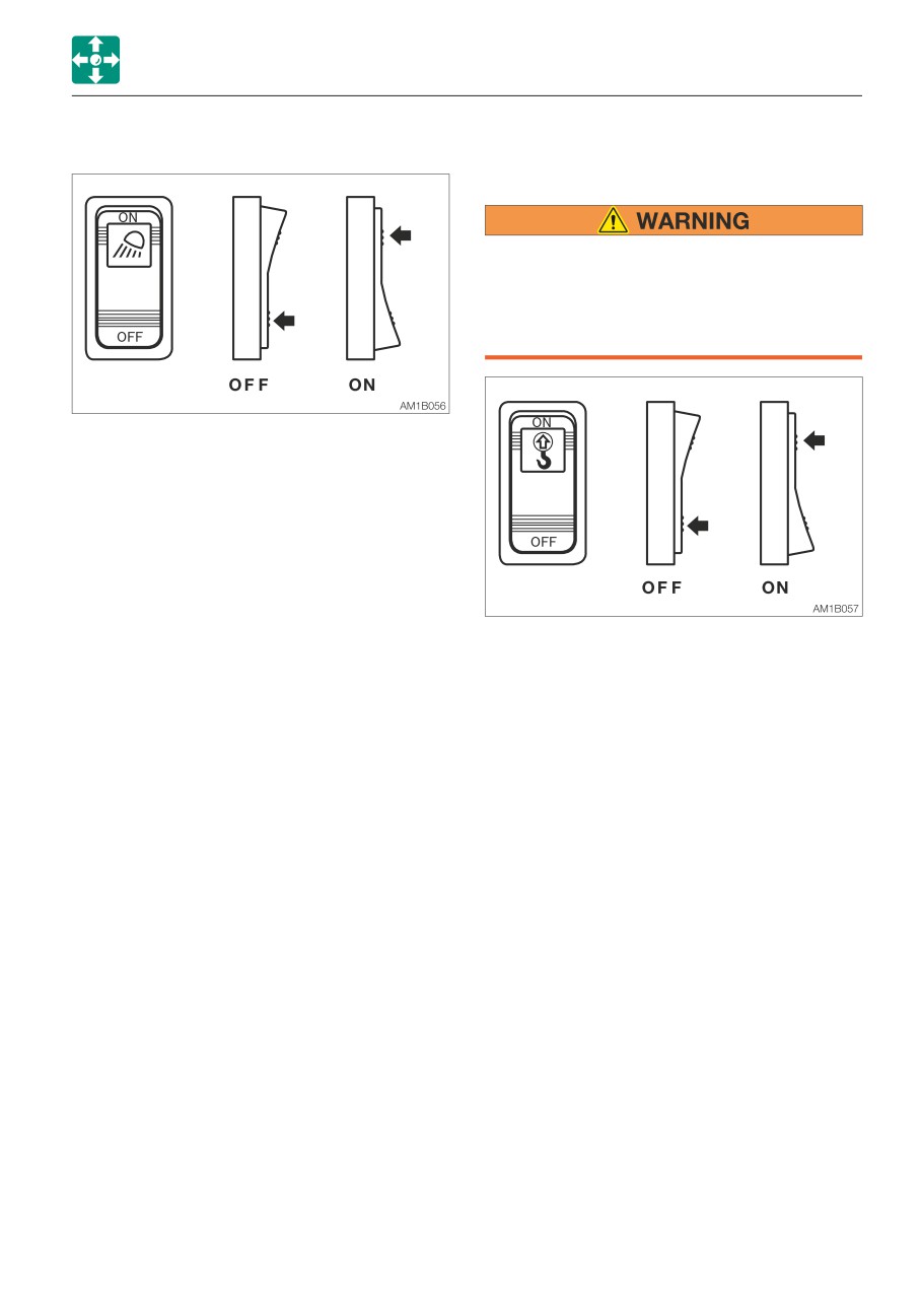
LIGHT SWITCH
LIFT OVERLOAD WARNING SWITCH (IF
EQUIPPED)
If the overload is not removed after the
overload warning horn is sounded, the
machine may tip over. If the horn starts
sounding, stop operating the machine
and lighten the load.
When this switch is turned while the starter
switch is at ON, the lights turn on as follows:
OFF
Off
ON
Switch lamps, front light, boom
light, side lights and tail lamps will
be lit. (switch lamp is lit)
If a weight greater than the lifting capacity is
applied or lifted, the overload warning device
is activated and the horn sounds. (When the
lift overload warning switch is turned on.)
OFF
Off
ON
On
2-45
CONTROLS
SWITCHES
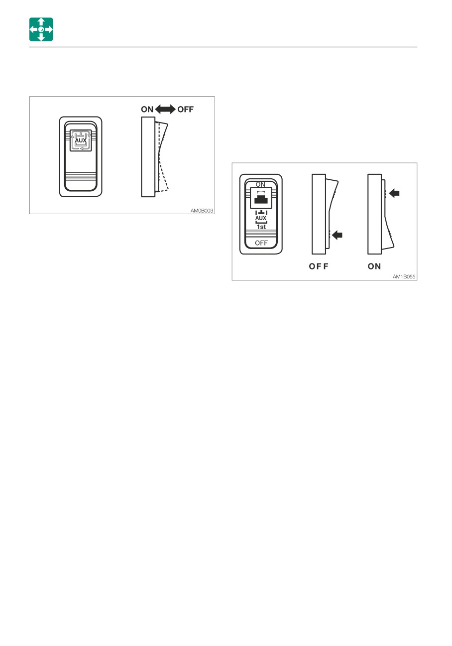
AUXILIARY 1ST FLOW RATE SELECT
DETENT MODE SWITCH (AUXILIARY
SWITCH
1ST)
IMPORTANT: Do not operate the machine
in the detent mode for a long time. Doing
so will increase the hydraulic oil
temperature and shorten the service life
of the hydraulic units.
This switch is used to select the flow rate of
the auxiliary 1st.
The auxiliary 1st flow rate indicator lamp in
the Multi-information display turns on to
indicate which flow rate setting is selected.
The flow rate changes each time the ON side
of the switch is pressed.
This switch is used to change the operation
The flow rate is set by using the Multi-
mode of the auxiliary 1st button (A). Pressing
information display.
the ON side of the switch causes the
Refer to “Service flow setting” on page 2-30.
auxiliary button (A) to enter the detent mode.
Pressing the OFF side changes to the
momentary mode.
2-46
CONTROLS
SWITCHES
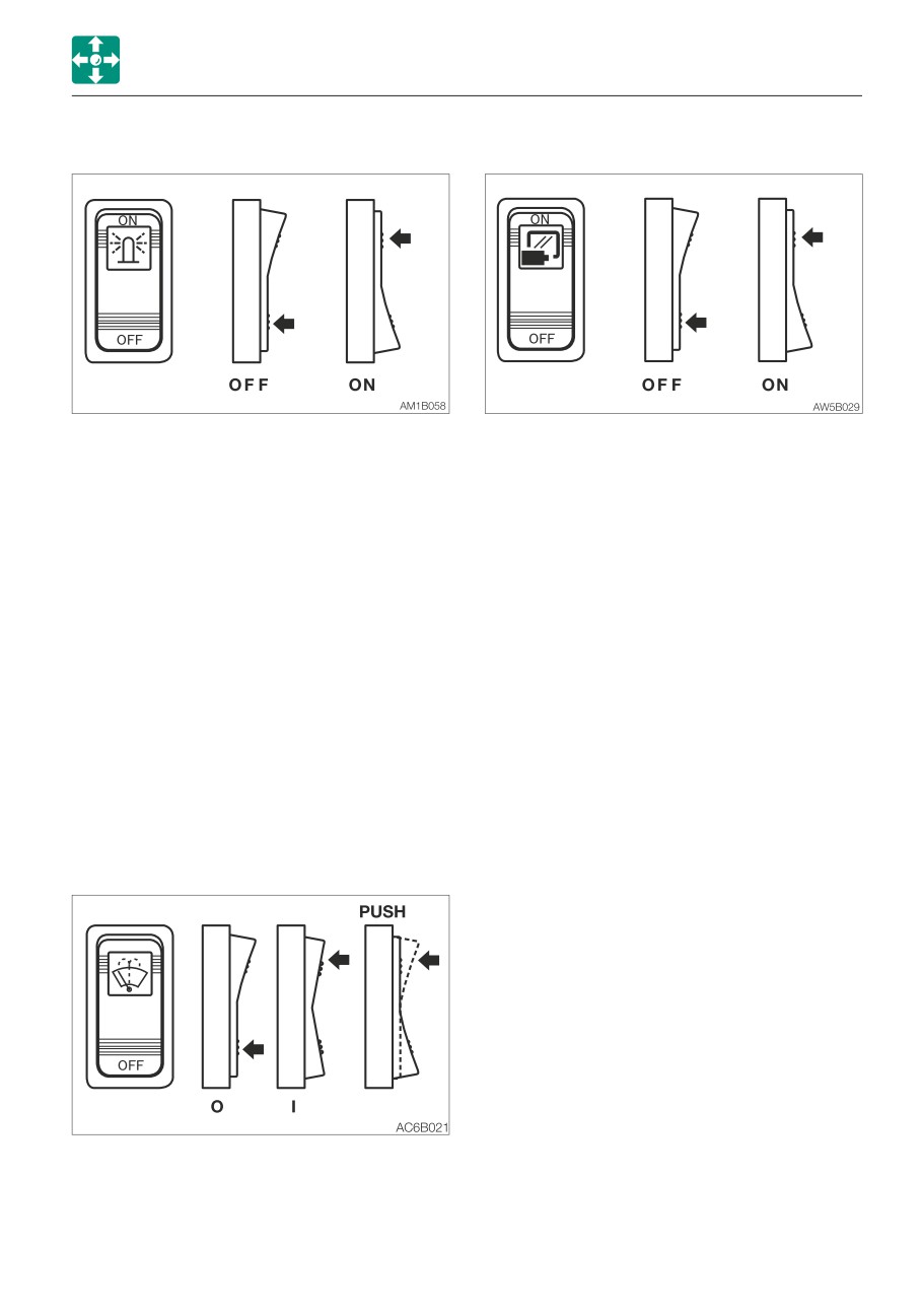
BEACON LAMP SWITCH
IMAGE SELECT SWITCH (CAMERA)
When this switch is turned on while the
Press the ON (symbol) side of this switch to
starter switch is at ON, the lamp turns on as
show the camera image captured by the
follows:
external camera at the top of the screen.
OFF
Out
OFF
Original screen
ON
Beacon lamp is lit
ON
Rear camera
LOWER WIPER SWITCH (IF EQUIPPED)
IMPORTANT: If no washer fluid is
discharged, do not operate the washer.
Doing so may damage the pump.
IMPORTANT: Operating the wiper with no
moisture on the windshield will scratch
the glass. Use water or washer fluid when
operating the wiper.
IMPORTANT: In cold climates, the wiper
blade may freeze to the glass. Operating
the wiper forcibly may damage the wiper
motor.
O
Off
I
Wiper operates
PUSH
Sprays washer fluid when
pressed. Stops when released.
2-47
CONTROLS
LEVERS AND PEDALS
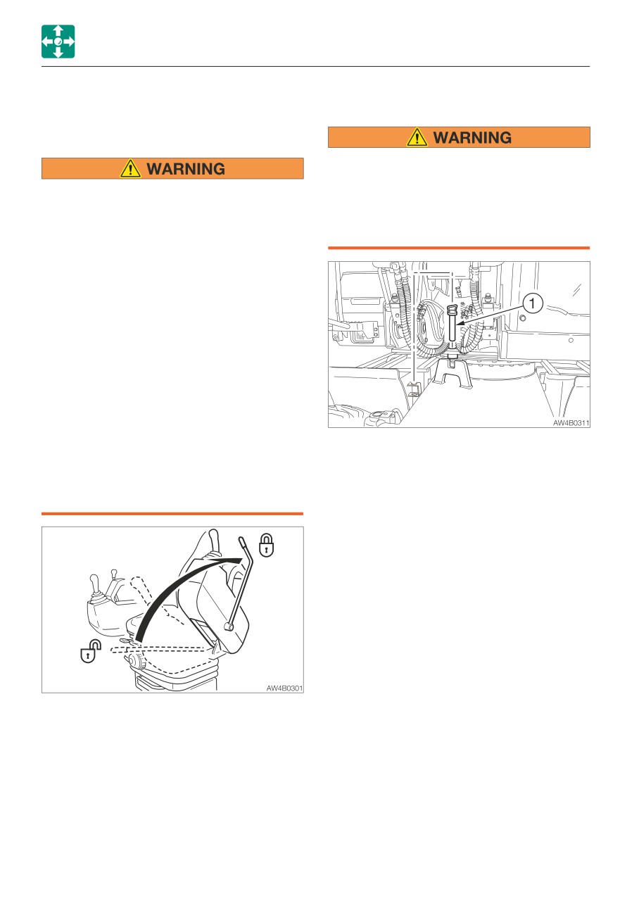
SLEW LOCK PIN
LEVERS AND PEDALS
SAFETY LOCK LEVER
When transporting or traveling on a road, be
sure to lock slewing with the slew lock pin.
• Before standing up from the operator’s
Otherwise, the upperstructure could slew
seat to open/close the window or
and cause a serious accident if a sudden
remove/install the lower window, lower
load is applied to the upperstructure at
the working equipment to the ground,
times, such as when turning.
raise the safety lock lever to engage the
lock and stop the engine. If any control
is accidentally touched when the safety
lock levers is lowered (unlocked), the
machine will suddenly move and cause
serious injury or death.
• Be careful not to touch the operating
levers when raising or lowering the
safety lock levers.
• Before leaving the operator’s seat, lower
the working equipment to the ground,
set the locking devices securely to the
lock position and stop the engine. Also,
To lock the upperstructure for transport and
be sure to remove the key, lock the cab,
on-road driving use the pin as follow:
fuel filler cap and covers, take the key
1. Lift the pin (1).
with you and store it in a specified
2. Align the upperstructure in parallel with the
place.
undercarriage.
3. Lower the pin (1) fully into the lock.
IMPORTANT: The machine may be
damaged if slewing is attempted by force
while it is locked. Check the position of
the slew lock pin before slewing.
This device is for locking the operations of
hoe attachment, slewing, auxiliary hydraulic
circuits, blade (outriggers) and traveling.
When the lever is raised, the lever stand
springs up to lock the lever.
2-48
CONTROLS
LEVERS AND PEDALS
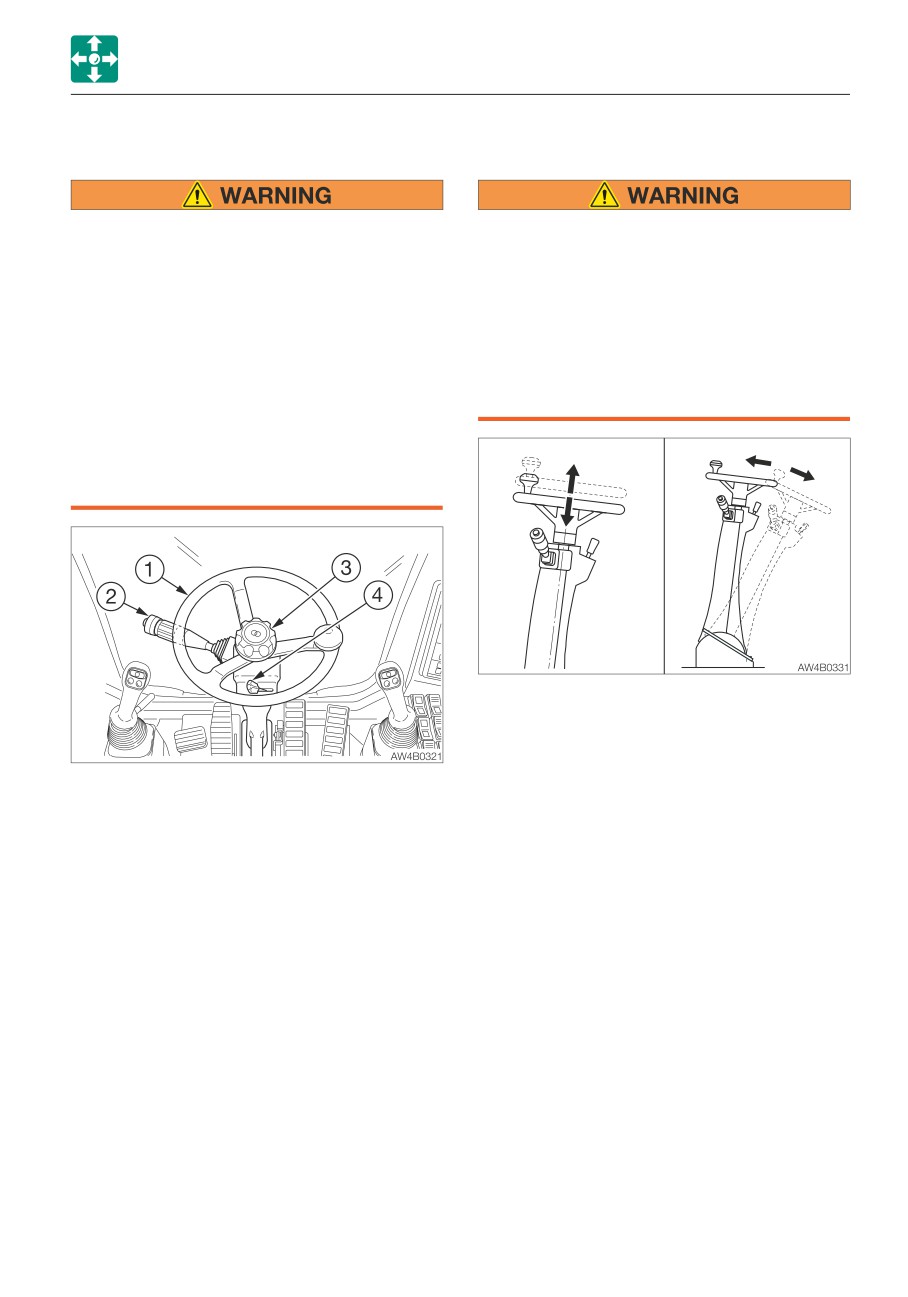
STEERING WHEEL
Adjusting the position of the steering
wheel
• Check the position of the undercarriage
• Adjust the position of the steering wheel
(steering device) before traveling.
before driving the machine.
Before operating the travel pedal, make
If you adjust it while driving the
sure that the steering device is to the
machine, steering will become unstable,
front of the operator’s seat. Remember
possibly resulting in an accident.
that when the steering device is to the
• After adjusting, check that the steering
rear of the operator’s seat, the steering
wheel is securely fixed in place.
wheel must be operated in the reverse
Unsecured steering wheel is dangerous,
direction from when it is to the front.
as it could be moved unexpectedly.
• Keep in mind that the steering wheel
operation is not possible when the
engine is stopped or if the steering
pump becomes faulty.
The position of the steering wheel can be
adjusted in up/down and front/back
directions.
The steering device contains the steering
Up /Down
wheel (1) and the turn signal lever (2) for
1. Turn the cap (3) counterclockwise and pull
driving.
up or push down the wheel.
Change direction by carefully turning the
2. Tighten the cap (3).
wheel. The additional steering knob makes
the steering wheel movement easier.
Forward /backward
The steering wheel operation is available only
1. Press the lever (4) to the right and tilt the
when the engine is running or the steering
steering wheel forward or backward.
pump is properly working.
2. Release the lever (4) at the desired angle.
< For Germany >
The machines for the German market are
equipped with the emergency steering wheel
function which allows steering wheel
operation even if the engine is stopped. Note
that, compared to a normal steering wheel
operation, it requires twice as much force to
turn the emergency steering wheel to turn to
the desired turning angle of wheels.
2-49
CONTROLS
LEVERS AND PEDALS
TURN SIGNAL LEVER
BRAKE PEDAL
• When parking, depress the braking
pedal all the way down to engage the
pedal lock so that the machine cannot
start while parked.
• Release the brake pedal lock before
start traveling.
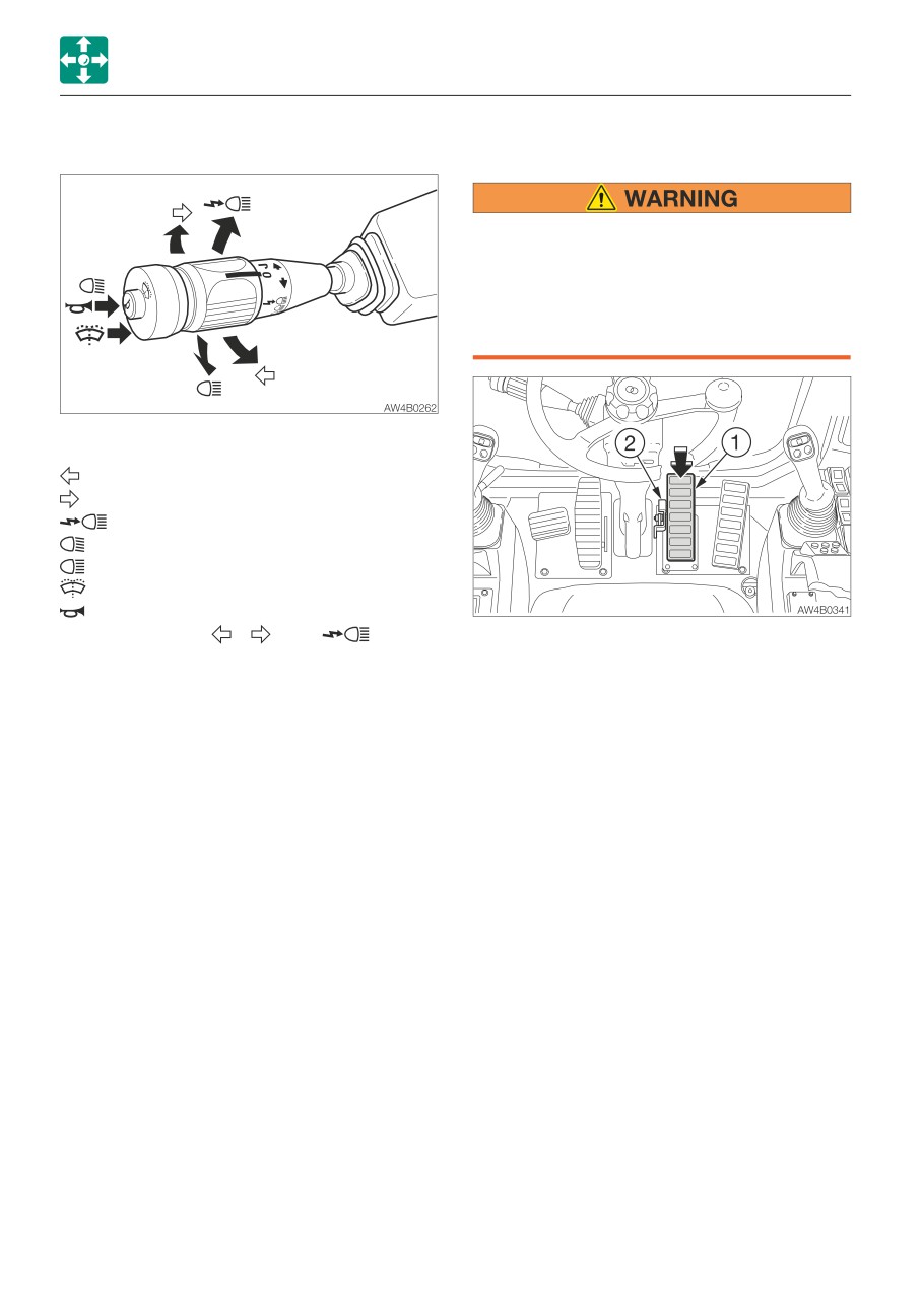
Use this lever to operate the turn signal
lights, headlights, wiper and horn.
...................Left turn lights
...................Right turn lights
..............Flash passing
Neutral:
Low beam
..................High beam
Push
Washer
Push
Horn
Note: The above (
), (
) and (
) can be
The brake pedal (1) is used to activate a
operated even when the power is turned off.
brake (arrow indicates the depression).
The pedal (1) can be locked by fully
Wiper operation
depressing it. Press on the Release lever (2)
O
Off
to release the lock.
J
INT (intermittence)
Locking the brake pedal will cause the
I
On
machine to enter the digging mode.
IMPORTANT: Be sure to lock the brake
pedal when using the bucket.
2-50
CONTROLS
LEVERS AND PEDALS
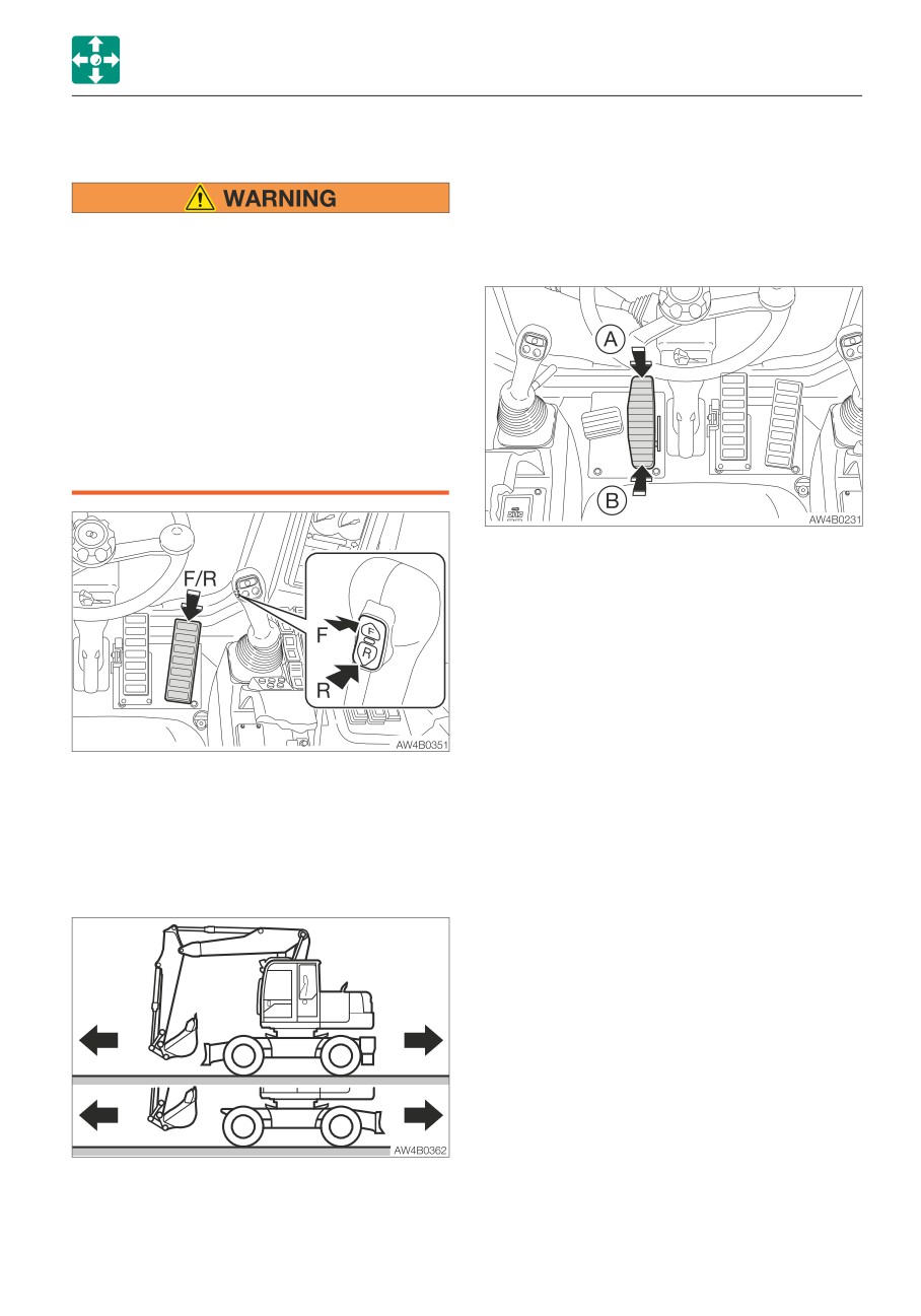
TRAVEL PEDAL
Use the travel select button to change the
travel direction (forward or reverse).
Refer to “Travel select button” on page 2-43.
• Check the position of the undercarriage
(steering device) before traveling.
SECOND BOOM PEDAL (2-PIECE BOOM)
Before operating the travel pedal, make
sure that the steering device is to the
front of the operator’s seat. Remember
that when the steering device is to the
rear of the operator’s seat, the steering
wheel must be operated in the reverse
direction from when it is to the front.
• Before traveling in reverse, check that
the area in the rear is clear of any
person.
Use this pedal to operate the second boom.
(A)
Second boom raise
(B)
Second boom lower
Refer to “Operating the second boom” on
page 3-18.
Use this pedal to drive the machine and to
control the travel speed.
This pedal can also be used to control the
engine RPM if the travel pedal button has
been pressed to enter the foot accelerator
mode.
F
Forward travel
R
Reverse travel
2-51
CONTROLS
LEVERS AND PEDALS
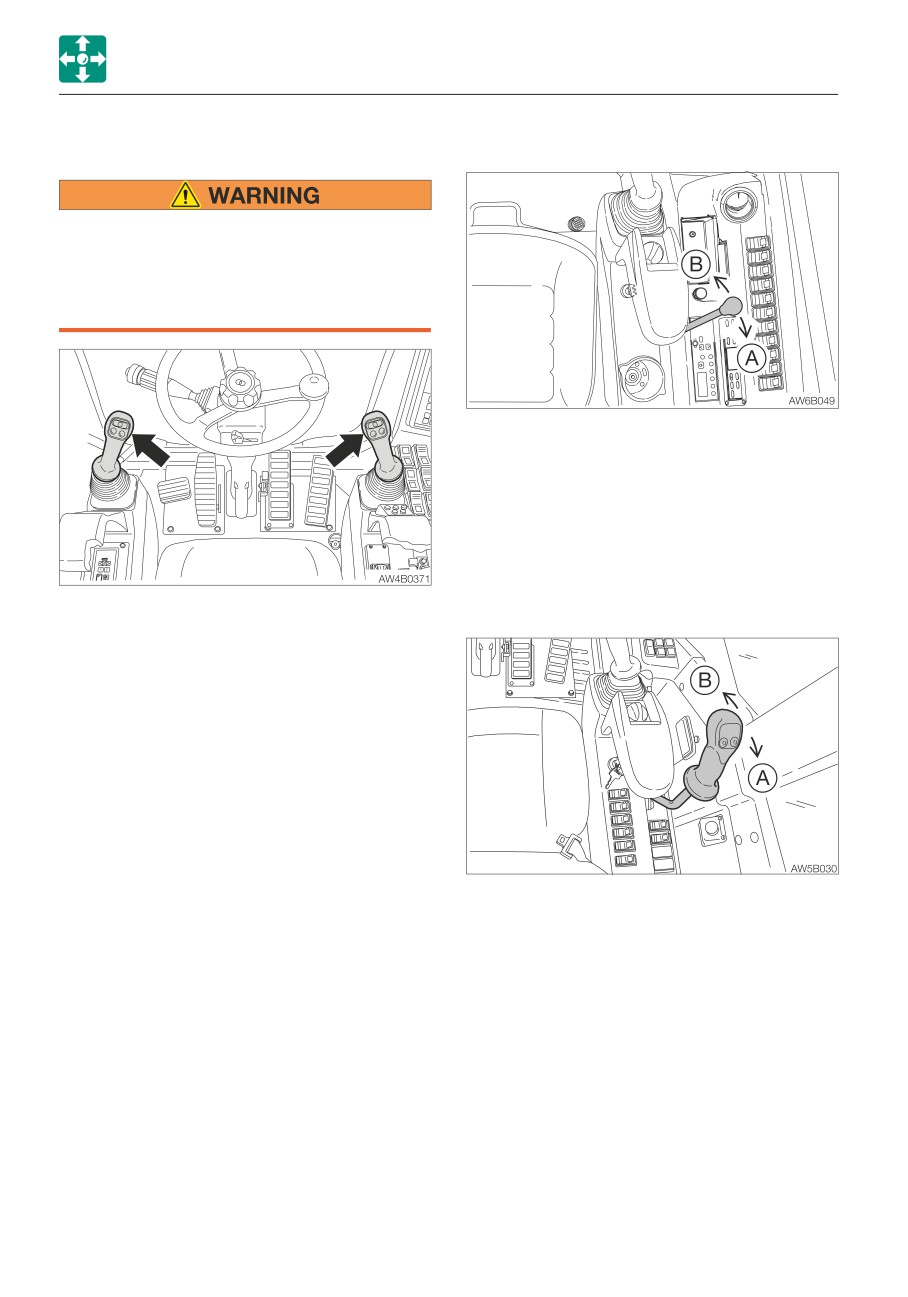
OPERATING LEVERS
BLADE LEVER
• Before starting operation, carefully
check which lever pattern you are going
to use.
• It is described using the ISO pattern in
this manual.
Use this lever to operate the dozer blade.
(A)
Blade up
(B)
Blade down
Refer to “Operating the dozer blade” on
page 3-18.
BLADE /OUTRIGGER LEVER
Use these levers to operate the boom, arm,
(IF EQUIPPED)
bucket and upperstructure.
Refer to “Lever pattern” on page 3-6.
Refer to “Operating the working equipment”
on page 3-16.
Use this lever to operate the dozer blade or
the outrigger (if equipped).
Use the outrigger switch to select the dozer
blade or outrigger operation.
(A)
Blade raise /Outriggers raise
(B)
Blade lower /Outriggers lower
Refer to “Outrigger switches (If equipped)”
on page 2-44.
Refer to “Operating the dozer blade” and
“Operating the outriggers (If equipped)” on
page 3-18.
2-52
CONTROLS
AIR CONDITIONER
Do not turn on the air conditioner until the
AIR CONDITIONER
engine is started
CAUTIONS ON USE
To avoid placing an excessive load on the
compressor, wait until the engine is started
Ventilate periodically
and is running smoothly before turning on
• When using the air conditioner over an
the air conditioner.
extended period of time, open the
windows about once each hour to let in
Let hot air out first
fresh air.
If the machine has been parked in the sun,
• Your eyes may become irritated if you
open the windows and door to let the hot air
smoke while using the air conditioner. If this
out of the cab before using the air
happens, open the windows to let in fresh
conditioner.
air Smoking particularly irritates the eyes
when the air conditioner is being used.
Caution on refrigerant (gas)
Since the humidity in the cab drops, the
If the refrigerant comes in contact with skin
cornea becomes dry.
or eyes, it may cause frostbite or eye
• If the outside air is dirty, set the air
damage. Never touch the refrigerant or
conditioner to the circulation mode.
loosen the parts on the cooling circuit.
If the refrigerant gas leaks, keep flames
Always maintain good visibility
away.
Working with the dirty windows or fogged
windows restricts visibility and is dangerous.
Off-season inspection
Always clean dirt and moisture off the
Even off season, run the air conditioner for 3
windows before working.
to 5 minutes at least once a week to
• The windows tend to get foggy when the
maintain oil in the various parts of the
humidity is high. If this happens, turn on
compressor.
the air conditioner to use outside air and
the defroster to get rid of the fog.
• If the air conditioner is set to high when
using the defroster, the difference between
the external and internal temperatures
increases, resulting in frost on the outside
of the windows. If this happens, either turn
the air conditioner off or push the
temperature control button to increase the
internal temperature.
• Mist may blow out of the air outlets. This is
not a malfunction. When moist air passes
through the evaporator on the air
conditioner unit, water particles in the air
freeze and are emitted as mist.
Do not overcool
For health reasons, the air inside the cab
should be kept at a temperature at which
you feel a little cool when entering the cab
from outside (a difference of 5 to 6°C (41 to
43°F)). Remember to adjust the temperature
properly.
2-53
CONTROLS
AIR CONDITIONER
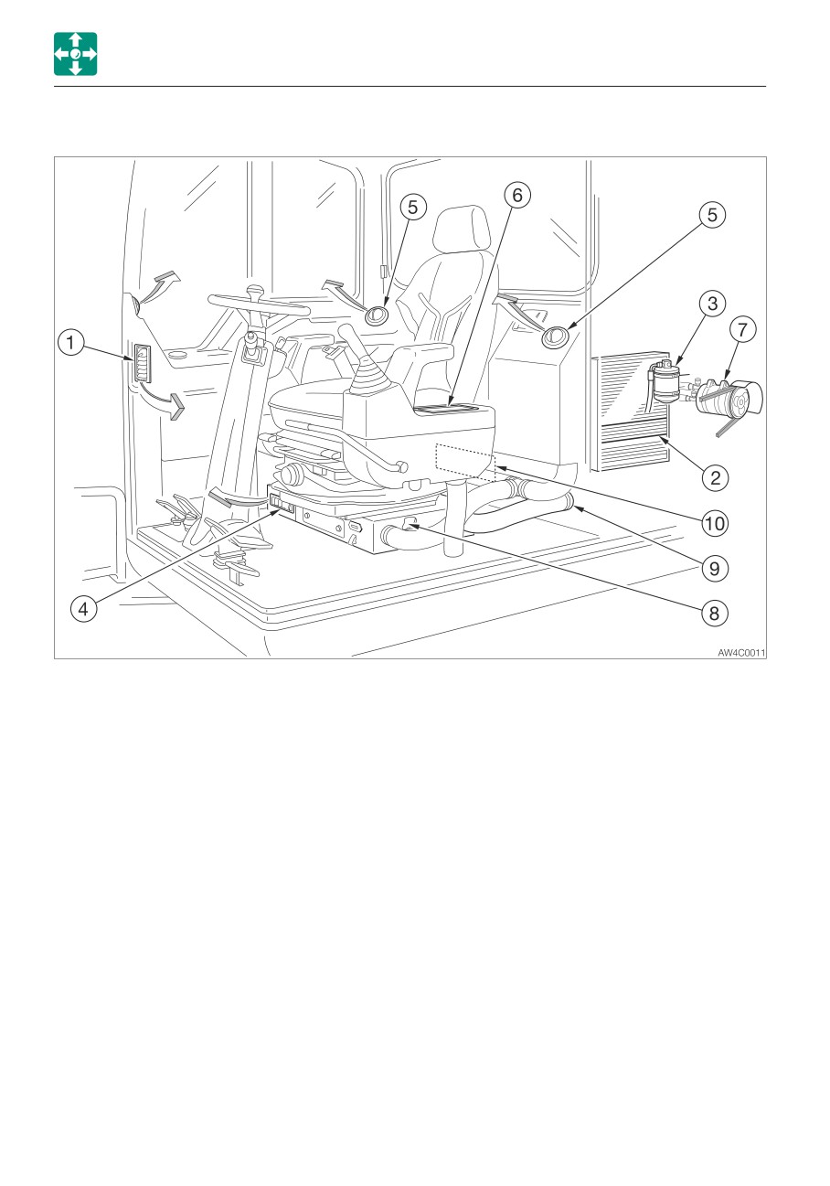
NAMES OF COMPONENTS
1. Defroster
2. Condenser
3. Receiver dryer
4. Foot outlet
5. Back outlets
6. Control panel
7. Compressor
8. Air conditioner unit
9. External air duct
10. Filter
2-54
CONTROLS
AIR CONDITIONER
CONTROL PANEL OPERATION
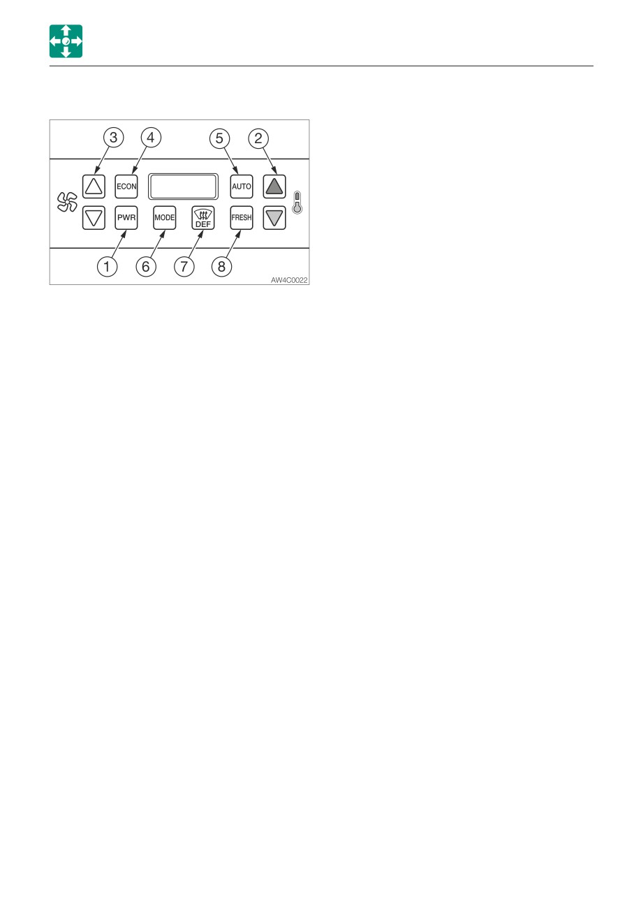
(5) AUTO
Places the system in a fully automatic
temperature control mode including fan
speed. A panel indicator light indicates when
this mode is active. The system will adjust
the blower fan speed to the lowest setting
necessary to maintain the cab temperature
at the displayed set point temperature.
(6) MODE (°C/°F)
Toggles the display units between degrees
Celsius and degrees Fahrenheit. The display
will show the units selected.
(1) PWR
Powers vehicle Heater-A/C control system
(7) DEF (Defrost icon)
on or off. The LED numeric display is
Positions the fresh /recirc air door to the
illuminated when the unit is turned on. The
fresh position and turns on the A/C
display will show the current set point
compressor clutch for dehumidification. A
temperature.
panel indicator light indicates when this
mode is active. Note that selecting defrost
(2) TEMPERATURE UP /DOWN
may override previous setting for ECON or
Increments the set point temperature up or
FRESH. This will be indicated by the state of
down. The system will control the electronic
the ECON and FRESH key indicator lights.
water valve and/or the A/C compressor
When the defrost mode is de-selected, the
clutch to hold the cab temperature as closely
system will return to previously selected
as possible to the set point temperature.
modes.
(3) FAN UP/ DOWN
(8) FRESH
Overrides the automatic fan speed control
This key toggles the fresh or recirculation air
(AUTO) feature. Increments fan speed up or
modes. When the FRESH mode is enabled,
down in 11 steps. The digital display
outside air is allowed into the vehicle. A panel
indicates the fan speed setting as a
indicator light indicates when this mode is
percentage or “HI” when maximum fan
active. Note that the defrost mode (DEF) will
speed is reached or “LO” when the minimum
override the FRESH function and enable the
fan speed is reached. The speed setting will
fresh air mode.
be shown for 5 seconds before returning to
the set point temperature display. The fan
speed is maintained until it is changed or if
the AUTO key is depressed.
(4) ECON (Economy Mode)
When depressed, locks out the A/C function.
The control used only fresh air, fan speed,
and water valve control to maintain the set
point temperature. Depressing the ECON
key will return the system back to normal
operation. An indicator light on the digital
display indicates when this mode is active.
Note that defrost (DEF) overrides the ECON
function.
2-55
CONTROLS
AIR CONDITIONER
GENERAL SYSTEM OPERATION
DEFROSTING OR DEFOGGING
OPERATION
Heater Operation
The ATC automatically controls the Heater-
Note: If the air conditioner is set to high
A/C to maintain the cab air temperature
when using the defroster, the difference
close to the set point selected by the
between the external and internal
temperature control pushbuttons. The ATC
temperatures increases, and fog may form
will adjust the air temperature blown through
on the outside of the windows. If this
the ducts to maintain this temperature. If
happens, either turn the air conditioner OFF
more heat is desired, increase the set point
or push the temperature control button to
temperature by pushing the up temperature
increase the internal temperature.
button. If less heat is desired, decrease the
This mode is used to be-ice, defrost, or
set point by pushing the down temperature
defog the windows by pressing the key with
button.
the defrost icon. In certain cold or humid
To obtain maximum heating, set the set point
conditions, more heat and airflow is required
temperature to 32°C (90°F). The system will
to clear the windows. The set point
put out maximum heat continuously, even if
temperature and the blower speed should be
the cab temperature exceeds the set point
adjusted as necessary to maintain a clear
temperature. Turn the blower fan speed to
windshield at all times. For maximum defrost,
maximum fan (not AUTO).
increase the set point temperature to the
In AUTO mode, the fan speed will increase
maximum setting (32°C or 90°F) and
as necessary to warm up the cab to the set
increase the blower speed to maximum fan
point temperature. Once the cab reaches the
(not AUTO).
set point temperature, the fan speed will
The air conditioner is enabled when in
decrease.
defrost mode. The A/C is used to dehumidify
Finer temperature control can be obtained by
the air entering the cab to remove the fog
leaving the control panel in °F units. The
from the windshield.
temperature units can be changed from °C
The fresh/recirc door is forced to the fresh
to °F or °F to °C by toggling the °C/°F
position in defrost mode. Fresh air is used to
button. The current temperature unit will then
help remove the fog from the windshield.
be shown on the digital display.
Pressing the defrost key when it is active
A comfortable set point for heating is
(indicated by an illuminated light) will
between 22°C (72°F) and 26°C (78°F).
deactivate the defrost mode and the system
Change the temperature set point inn small
will return to the settings that were in place
amounts for best results. Once a
before the defrost mode was enabled.
comfortable temperature is reached, this
temperature will be maintained without
adjusting the set point
2-56
CONTROLS
AIR CONDITIONER
AIR CONDITIONER (A/C) OPERATION
VENTILATION (FRESH /RECIRC)
The unit draws in a mix of outside and
recirculated air when in fresh air mode. This
• When the air conditioner is set to the
allows the cab to maintain a positive cab air
recirculation mode, the air in the cab
pressure to prevent excessive dust from
gradually becomes dirty, so switch to
entering the cab. In addition, the fresh air
external air ventilate once a comfortable
mode prevents the air from becoming stale
temperature is reached.
and humid.
• Excessive cooling can be harmful to
In recirculation mode, only recirculated air is
your health. It is best to keep the air
pulled in through the unit. Use this mode for
inside the cab only about 5 to 6°C (41 to
short periods of time to prevent fumes from
43°F) cooler than the outside air.
entering the cab or to obtain maximum
• If the excavator has been parked in the
cooling or heating.
sun, open the windows or door to let
Inspect and replace both the fresh air and
the hot air out of the cab before using
recirculated air filters regularly to obtain
the air conditioner.
proper cab pressurization, optimized unit
performance, and correct temperature
The ATC automatically controls the Heater-
regulation.
A/C to maintain the cab air temperature close
to the set point selected with the temperature
control pushbuttons. The ATC will adjust the
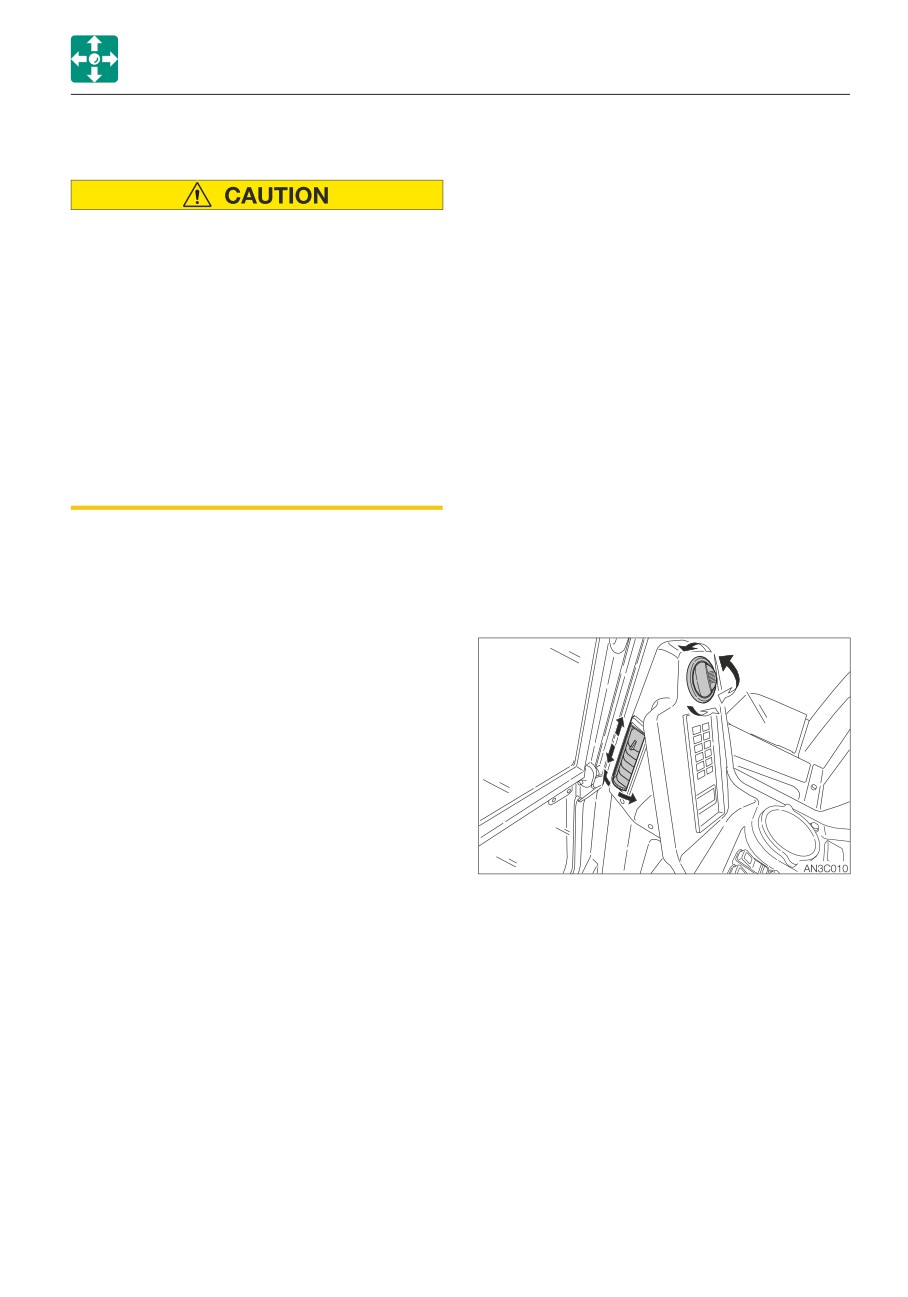
OUTLETS
air temperature blown through the ducts to
maintain this temperature. If more cooling is
desired, decrease the set point by pushing
the down temperature button.
To obtain maximum cooling, set the set point
temperature to 16°C (60°F). The system will
put out maximum cooling continuously, even
if the cab temperature drops below the set
point temperature. Turn the blower fan speed
to maximum fan (not AUTO).
In AUTO mode, the fan speed will be adjusted
as necessary to keep the cab at the set point
temperature. The farther away the cab
Move the louvers to adjust the air flow
temperature is from the set point, the higher
direction.
the fan speed.
Finer temperature control can be obtained by
leaving the control panel in °F units. The
temperature units can be changed from °C to
°F or °F to °C by toggling the °C/°F button.
The current temperature unit will then be
shown on the digital display.
A comfortable set point for cooling is between
20°C (68°F) and 23°C (74°F). Change the
temperature set point in small amounts for
best results. Once a comfortable temperature
is reached, this temperature will be
maintained without adjusting the set point.
2-57
CONTROLS
ACCESSORIES
CIGARETTE LIGHTER
ACCESSORIES
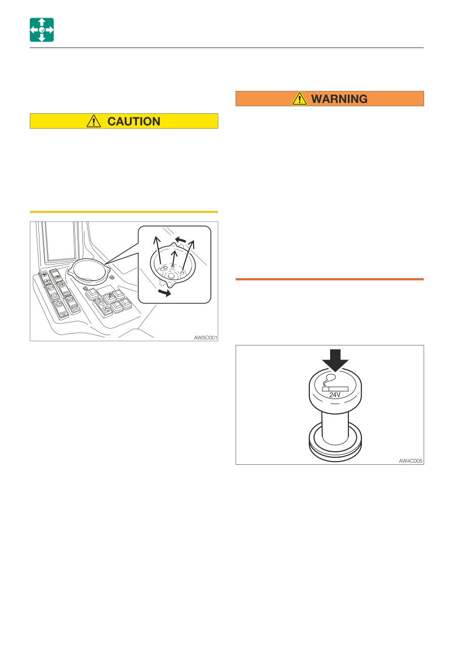
CUP HOLDER
• Do not leave the cigarette lighter knob
pushed in for a long time. Doing so
• Drinks may be spilled due to vibration
heats up the lighter, and could be
when the machine is operating or
dangerous.
traveling. Be particularly careful not to
• If the lighter knob does not pop out 30
burn yourself with hot drinks.
seconds after it was pushed in, it may
• Note that the cigarette lighter or other
be broken. Pull it out by hand.
electric parts may be damaged if drinks
• Do not use any other cigarette lighters
are spilled on them.
than Takeuchi’s. They could be stuck in
the middle and not pop out.
• Use only those electric products which
comply with the specifications of these
sockets.
• Do not touch the metallic parts of the
lighter. Doing so could cause burns.
This is the cigarette lighter and internal
power supply socket.
When using, be careful not to exceed
24V/5A.
Use to hold cups or bottles.
To warm or cool the cup, turn the cup holder
in counterclockwise. Worm or cool wind
blows from the bottom of the cup holder.
1. Push the lighter in.
2. Release the lighter and wait for it to pop
out. The lighter pops out automatically
when the heater becomes red hot.
3. Once the lighter pops out, pull it out.
2-58
CONTROLS
ACCESSORIES
ASHTRAY
OFF (O)
Lamp is turned off all the time,
with no regard for the door
being opened or closed.
Neutral (N)
Lamp is turned on when the
• Be sure to extinguish cigarettes and
door is opened, and it turned
matches completely before putting
off when the door is closed.
them in the ashtray, and close the
ON ( I )
Lamp is turned on all the time,
ashtray after each use.
with no regard for the door
• Do not overfill the ashtray with cigarette
being opened or closed.
butts or put in paper or other easily
burnable objects. Doing so could cause
fire.
MIRRORS
AD6B021
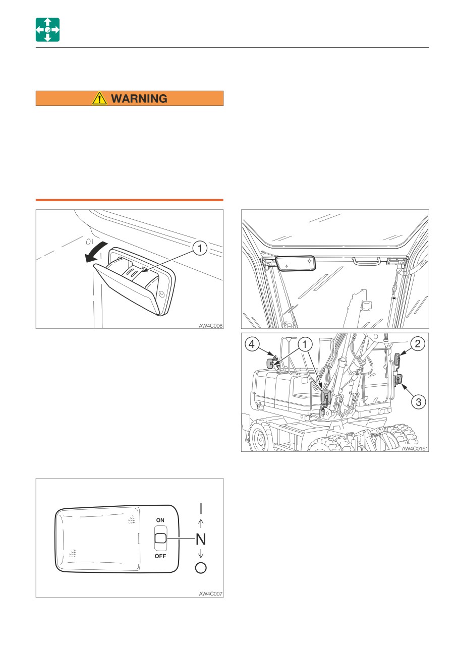
Pull the ashtray out towards you to use it. To
clean, press the ash discharge button (1) and
pull out the ashtray.
INTERIOR LIGHT
IMPORTANT: The battery capacity
decreases if the interior light is left on for
a long time when the engine is stopped.
Turn the lamp off when leaving the
machine.
Adjust the rear view mirrors and side view
mirrors so that you have a better view.
1. Check the rear right side view
2. Check the rear left side view
3. Check the left side view
4. Check the blind spot in the rear of the
machine
2-59
CONTROLS
ACCESSORIES
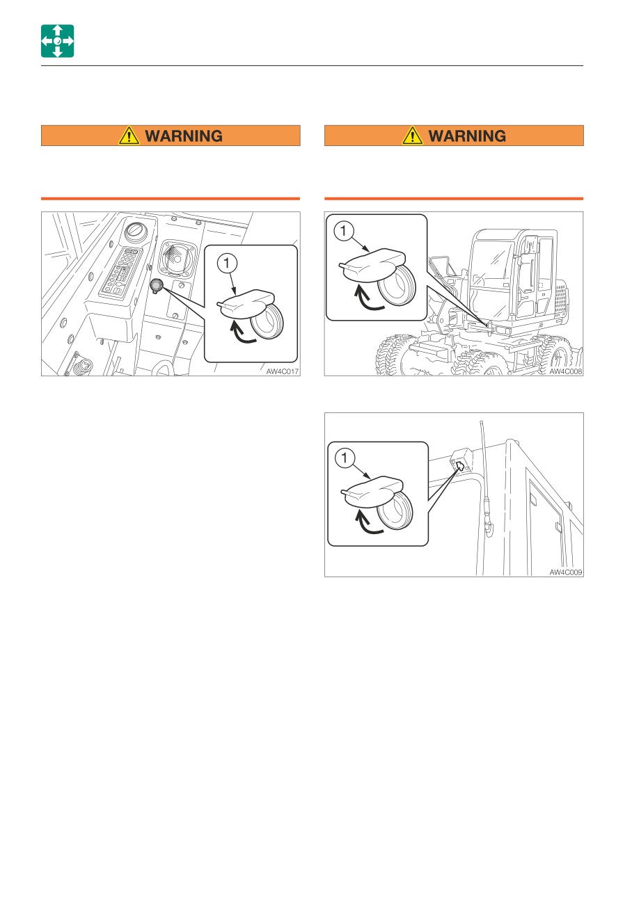
12 V POWER SOCKET
24 V EXTERNAL POWER SOCKETS
Use only those electric products which
Use only those electric products which
comply with the specifications of this
comply with the specifications of these
socket.
sockets.
Use this socket to connect the 12 V power
For beacon
supply. When using, be careful not to exceed
12 V/5 A.
To use, open the cap (1).
Use these sockets to connect the external
power supply. When using, be careful not to
exceed 24 V/5 A.
To use, open the cap (1).
2-60
CONTROLS
ACCESSORIES
RADIO (FOR CAB)
CAUTIONS ON USE
• To ensure safe operation of the machine, always be sure to keep the volume of the
radio down to a level where you can easily hear sounds from outside the machine.
• Do not use the radio for a long time when the engine is stopped. Doing so will drain
the battery and make it difficult or impossible to restart the engine.
• Be careful not to allow water or other liquids to come into contact with the radio.
Otherwise, it may result in malfunction.
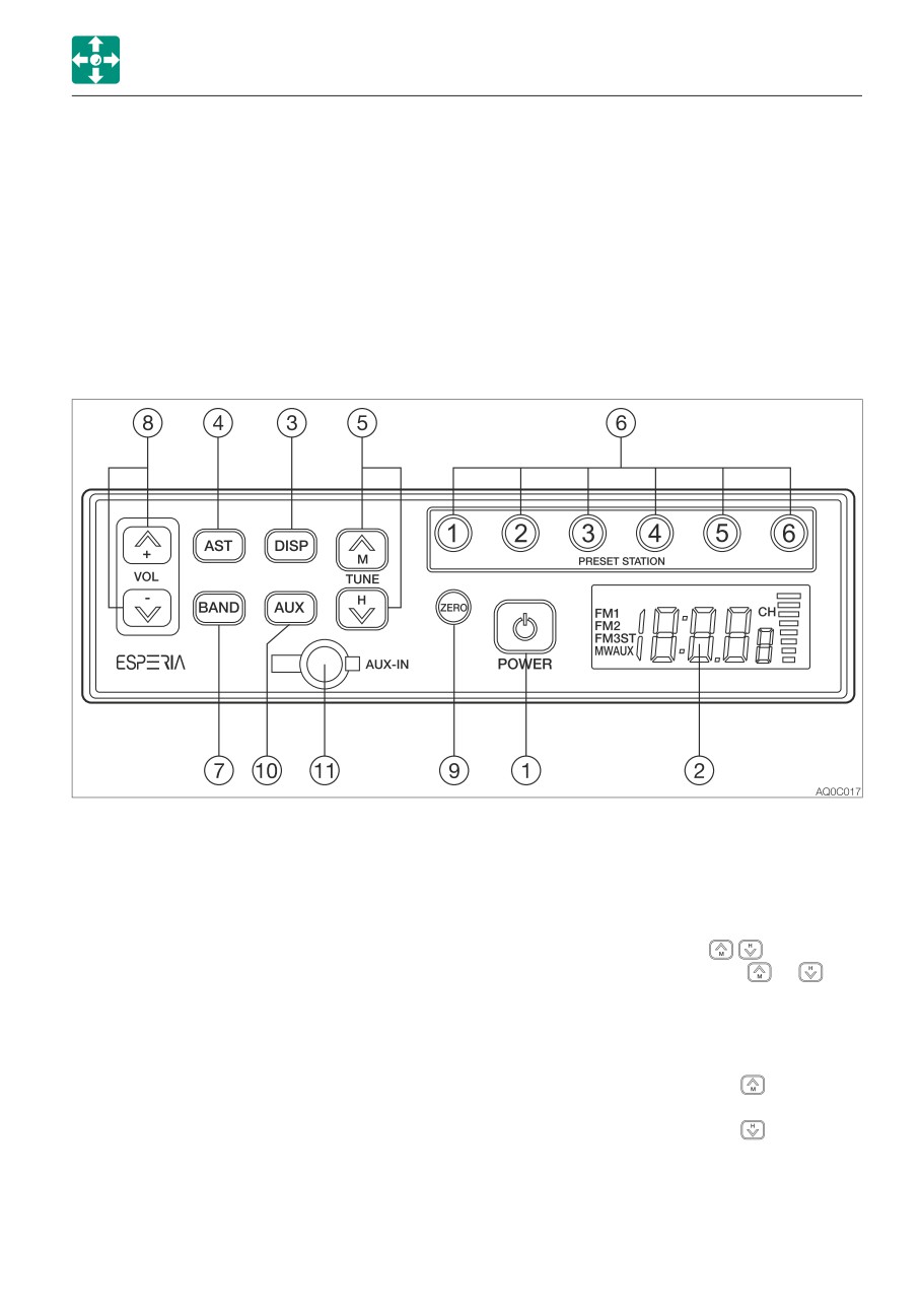
NAMES OF COMPONENTS
(1) POWER button
(4) Auto store /Auto seek station (AST)
Use this button to turn on or off the
Press this button to automatically assign
radio.
receivable radio stations to preset
buttons (1 to 6).
(2) LCD
Displays the time/the receiving frequency
(5) Tuning button (TUNE
)
and the operation mode.
Press and hold this button ( or
) for
one second or more to start seeking the
(3) Display button (DISP)
receivable stations. The seeking stops
Pressing this button while the frequency
when a station is found. To cancel tuning
is displayed on the LCD changes the
halfway, press the button again.
display to the clock. Pressing the button
Pressing the TUNE button
starts
again returns to the frequency. If the
seeking stations with higher frequency.
button is not pressed for five seconds,
Pressing the TUNE button
starts
the display returns to the frequency.
seeking stations with lower frequency.
The frequency changes as either button
is pressed in one second intervals.
2-61
CONTROLS
ACCESSORIES
(6)
Preset buttons (1 to 6) (PRESET
(11)Auxiliary input jack (AUX-IN)
STATION)
Use this jack to connect an external
Each button can store three FM stations
audio source such as a portable music
(FM1, FM2, FM3) and one MW (AM)
player. Pull off the rubber cap and
station. For how to set these buttons,
connect the output terminal (headphone
refer to “Presetting stations”.
jack) of the portable player to the AUX-IN
with the stereo mini-plug (3.5 mm) cord.
(7)
Band button (BAND)
Be sure that jack is closed with the
Pressing this button changes the band
rubber cap when not in use.
from FM1 to FM2, FM3 and MW (AM) in
this order. The received band and its
Playing the radio
frequency appear on the display.
1. Turn the ignition key to the ACC or ON
position, and then press the power button
(8)
VOL buttons
(1) to turn on the radio.
Use these buttons to control the sound
2. Select the band, FM or MW (AM) by
volume. Press the button
to increase
pressing the BAND button.
the volume and the button to
3. Select the station with the preset button or
decrease the sound volume. Press and
the tuning button, and adjust the volume
hold each button to continuously
with the volume button.
increase/decrease the volume.
4. To turn off the radio, press the power
button.
(9)
Clock zero set button (ZERO)
Use this button to set the minute to “00”
Selecting a station-auto select
when it is between “55” to “59” or “01”
Press and hold the TUNE button
for one
to “05”.
second or more to start seeking stations in
The LCD returns to the frequency display
the higher frequencies direction. Press and
if no more operation is performed for five
hold the TUNE button
for one second or
seconds.
more to start seeking stations in the lower
frequencies direction. The radio will stop
(10)Auxiliary input select button (AUX)
seeking when it finds an receivable station
Pressing this button changes the input
and start playing.
source to the external device connected
to the AUX-IN (11) jack. The display of
Selecting a station-manual select
“AUX” appears on the LCD. Pressing the
The selection can be done manually. Press
button again returns to the radio.
the tune
button to seek stations with
higher frequencies. Press the tune
button
to seek stations with lower frequencies.
2-62
CONTROLS
ACCESSORIES
Presetting stations
Auxiliary input (AUX)
1. Press the BAND button to select a band
• Connect a portable audio player and listen
(MW (AM) or FM), and then select the
to your favorite music.
station by pressing the TUNE button for
• Plug a patch cord (without resistor) into the
seeking.
headphone jack of the audio player.
2. To assign the selected station to a preset
• Plug a stereo mini plug (3.5 mm) into the
button, press and hold the button to be
AUX-IN jack on the radio.
assigned for one second or more. The
• To listen to an external portable audio
number of the preset button appears on
player, press the AUX button. (The “AUX”
the LCD.
display appears on the LCD and the
3. For more stations to preset, repeat the
frequency display is changed to the clock
steps 1 and 2 above.
display.)
• If the preset button on which a station
• To return to the radio, press the AUX
has been assigned is pressed and held
button again.
for one second or more, the preset
• When connecting, adjust the sound volume
information will be modified.
level of the audio player so that it is same
• If the stored information is erased during
as that of the radio.
battery replacement on the vehicle,
• Adjust the sound volume of the audio
assign the stations again to the preset
player by using the volume control buttons
buttons.
on the radio.
• Each preset button (1 to 6) can store
• Do not connect a device with a larger
three FM stations (one from each FM1,
output compared with a portable audio
FM2, FM3) and one AM station.
player.
Auto storing (AST)
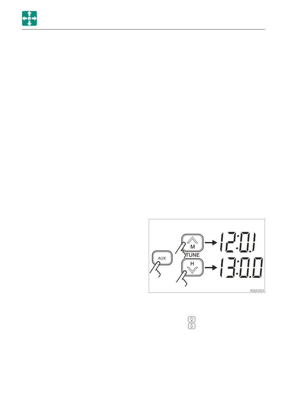
Setting the clock
Press the AST button while playing the radio.
The radio automatically starts seeking the
receivable stations within the band currently
selected and assign each preset button (1 to
6) a station.
Note: The previous stations stored will be
cleared (cancelled) by the auto storing. If the
station stored in the preset button is not
desirable, try to preset the station manually.
• If a frequency is displayed on the LCD,
press the AUX button (auxiliary input) to
display the clock.
• Use the tune
button to set the minute.
Use the tune
button to set the hour.
• To set the minute digits to “00” when they
are from “55” to “59” or from “01” to “05”,
press the ZERO button.
2-63
CONTROLS
ACCESSORIES
Resetting (North, Central and South
SPECIFICATIONS
America)
Power source:
12/24 VDC (negative
If there are any problems, such as the
ground)
abnormal display of frequency or failure of
Maximum power consumption:
selection, reset the radio by pressing the “3”
3A or less (at max. volume,
button* while pressing the AST button and
24 V)
the AUX button together. Then, “US”** and
Maximum output power:
the clock display appear on the LCD,
16 W + 16 W (4Ω) (at 28.8
indicating that the radio is turned off. Note
VDC input)
that the memory stored in the preset button
5W+5W (4Ω) (at 14.4 VDC
is cleared.
input)
:
“6” button - (Europe, Asia, Oceania)
Rated output power:
“5” button - (China)
12 W + 12 W (10%
** : EU - (Europe, Asia, Oceania)
distortion, 4Ω) (at 28.8
CH - (China)
VDC input)
3.5 W + 3.5 W (10%
Switching the volume mode when the
distortion, 4Ω) (at 14.4
radio is on
VDC input)
Switch the modes between SU and FI by
Dimensions:
178 (W) x 50 (H) x 65 (D)
pressing the (1) button while pressing the
mm (excluding protrusions)
AST and AUX buttons together, when the
Receiving frequency:
radio is on.
MW (AM) 531 to 1602 kHz
The SU or FI display appears on the LCD,
(Europe, Asia), 530 to
followed by the radio turning off by itself.
1710 kHz (North, Central
SU mode: The volume at power-off is
and South America)
retained.
FM 87.5 to 108 MHz
FI mode:
The volume at power-off is
(Europe, Asia), 87.9 to 108
reset.
MHz (North, Central and
South America)
Practical sensitivity:
MW (AM) 32 dB or less
(S/N 20 dB)
FM 12 dB or less (S/N 30
dB)
S/N ratio:
MW (AM) 40 dB or more
FM 50 dB or more
AUX-IN:
Stereo mini jack (3.5 mm);
rated input, 90 mV; 20 kΩ
impedance
Note: Specifications and dimensions may be
changed without notice.
2-64
CONTROLS
ACCESSORIES
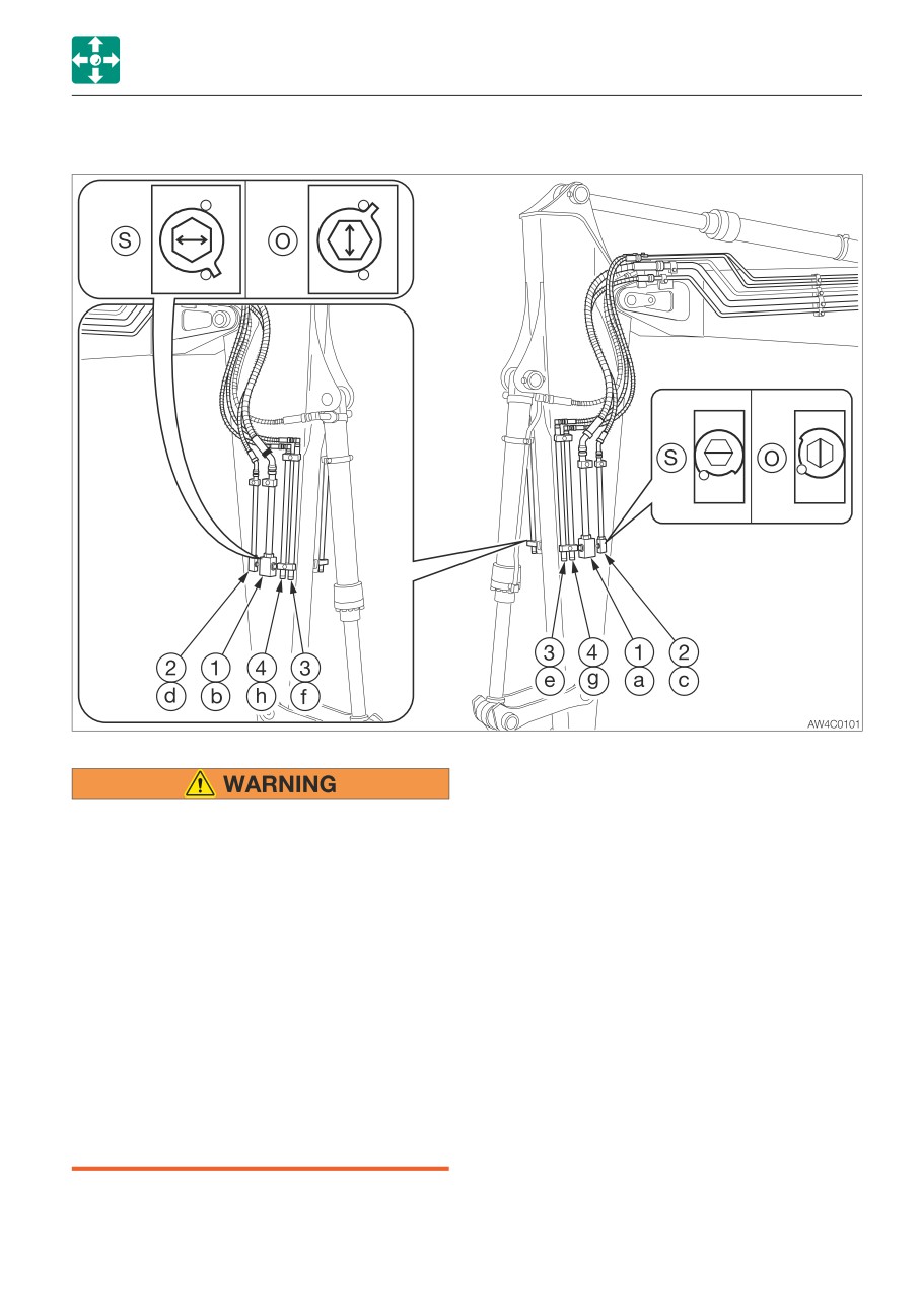
AUXILIARY HYDRAULIC LINES
These lines deliver the hydraulic oil necessary
for operating a hydraulic breaker, crusher or
Oil may spurt out if pipes disconnected
other attachments.
before releasing the pressure in the
hydraulic system.
(1)
First auxiliary hydraulic lines
• Immediately after the engine is stopped
(2)
Second auxiliary hydraulic lines
and while the safety lock lever is still in
(3)
Third auxiliary hydraulic lines
the unlock position, turn the starter
(4)
Fourth auxiliary hydraulic lines
switch to ON and press each auxiliary
hydraulic switch several times to
Stop valve
release the pressure from the auxiliary
(S) : Closed
hydraulic circuit.
(O) : Open
• Press the air breather button to relieve
the tank pressure.
• When disconnecting hoses, stand to the
side and loosen them slowly to
gradually release the internal pressure
before removing.
2-65
CONTROLS
ACCESSORIES
Connecting the hydraulic circuits
Disconnecting the hydraulic circuits
To connect the attachment hydraulic lines,
1. Release the pressure remaining in the
observe the following procedures:
lines, and then close the stop valve.
1. Release the pressure remaining in the
Refer to “Releasing the residual pressure”
lines, and then close the stop valve.
on page 2-67.
Refer to “Releasing the residual pressure”
2. Disconnect the lines from the ports (a/c)
on page 2-67.
and (b/d).
2. Remove the plugs.
3. Install the plugs.
3. Connect the attachment hydraulic lines to
ports (a/c) and (b/d). When installing a
hydraulic breaker, connect the supply
circuit to the port (a) and the return circuit
to port (b).
4. Open the stop valves. When installing a
hydraulic breaker, open the selector valve
(1).
Refer to “Selector valve” on page 2-68.
5. When connecting is complete, purge air
from the hydraulic lines.
a. Start the engine and run it at a low idle
speed with no load for 10 minutes.
b. With the engine running in low idle,
operate the auxiliary hydraulic switches
repeatedly (approx. 10 times) to purge
air from the hydraulic lines.
c. Stop the engine and wait for at least 5
minutes until bubbles escape from the
hydraulic oil in the tank.
IMPORTANT: Follow the procedures for
purging air as instructed by the
attachment manufacturer, if applicable.
6. Check for oil leaks.
2-66
CONTROLS
ACCESSORIES
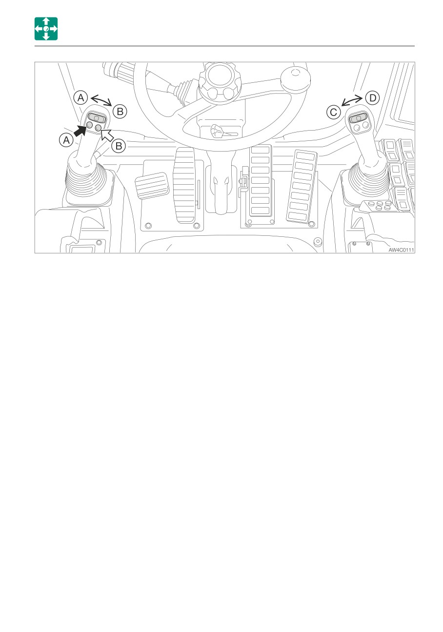
Operating
Releasing the residual pressure
Press those buttons to control the flow of the
After the auxiliary hydraulic circuits have
oil in the first/second auxiliary hydraulic lines.
been used, pressure remains in the circuits.
(A)
Hydraulic oil flows to left auxiliary line
This is called the residual pressure. Release
(a).
this residual pressure before disconnecting
(B)
Hydraulic oil flows to right auxiliary line
the lines.
(b).
Perform the residual pressure releasing
(C)
Hydraulic oil flows to left auxiliary line
within 10 minutes after the engine stopping.
(c).
1. Park the machine on a flat, rigid and safe
(D)
Hydraulic oil flows to right auxiliary line
ground.
(d).
2. Stop the engine.
3. Lower the safety lock lever to the
unlocked position.
4. Turn the starter switch to the ON position.
5. Press the auxiliary hydraulic switches
several times to release the residual
pressure in the auxiliary hydraulic circuitry.
2-67
CONTROLS
ACCESSORIES
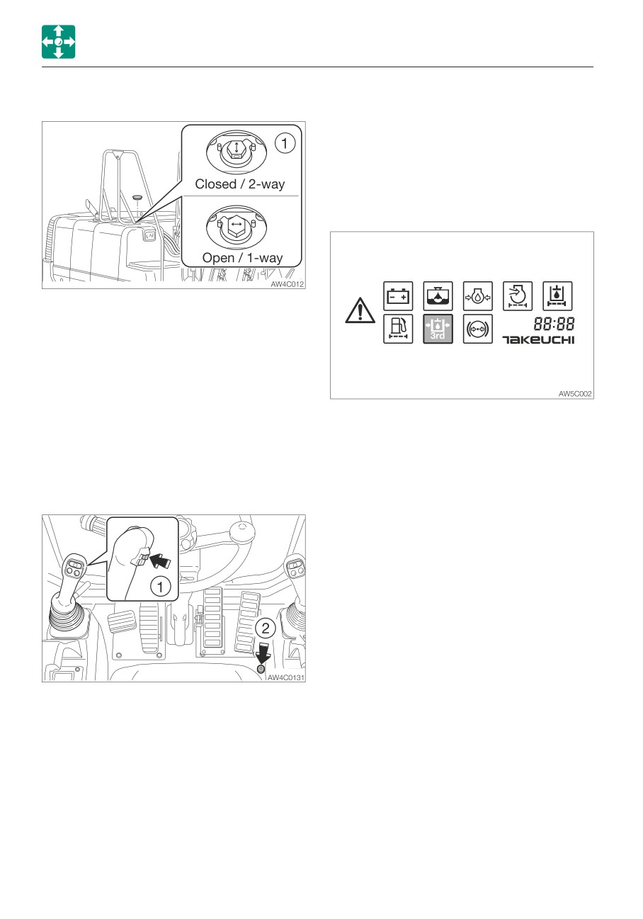
Selector valve
when the button (1) and the switch (2) are
pressed at the same time. When they are
pressed, the hydraulic oil flows into the line (f)
to increase the pressure there. As the result,
the pin on the bucket comes out and the
bucket is removed from the machine.
Third auxiliary hydraulic warning lamp
Open
When using a hydraulic breaker
(1-way flow)
Closed When using a reversible
attachment (2-way flow)
Change the direction of the hydraulic oil flow
by opening or closing the selector valve (1)
on the machine body.
Use the high-flow only in the 2-way flow. If it
This lamp illuminates and an alarm sounds
is used in the one-way flow, the brake may
when the third auxiliary hydraulic pressure
overheat.
drops abnormally, when the safety lock lever
is fully lowered to the unlocked position while
Third auxiliary hydraulic switch and
the engine is running.
button
The third auxiliary hydraulic lines are normally
used to control the “quick attachment”
installed to connect/disconnect the bucket.
When the safety lock lever is released after
the engine is started, hydraulic oil flows into
the pipe (e). This allows the pressure in the
(e) side to increase and to prevent the pin
inserted on the bucket from coming out. If
the pressure in the (e) side drops, the alert
that the bucket may come out is indicated by
the warning lamp and the alarm. For a safety
reason, the bucket can be disconnected only
2-68