Takeuchi compact excavator TB125, TB135, TB145 / diesel TNE / diesel Yanmar. Service Manual - page 66
 

  Index      Manuals     Takeuchi compact excavator TB125 (12510003~), TB135 (13510004~), TB145 (14510004~) / diesel TNE / diesel Yanmar. Service Manual


Search            copyright infringement  


Content      ..     64      65      66      67     ..


Takeuchi compact excavator TB125, TB135, TB145 / diesel TNE / diesel Yanmar. Service Manual - page 66


47

4.3.4. 

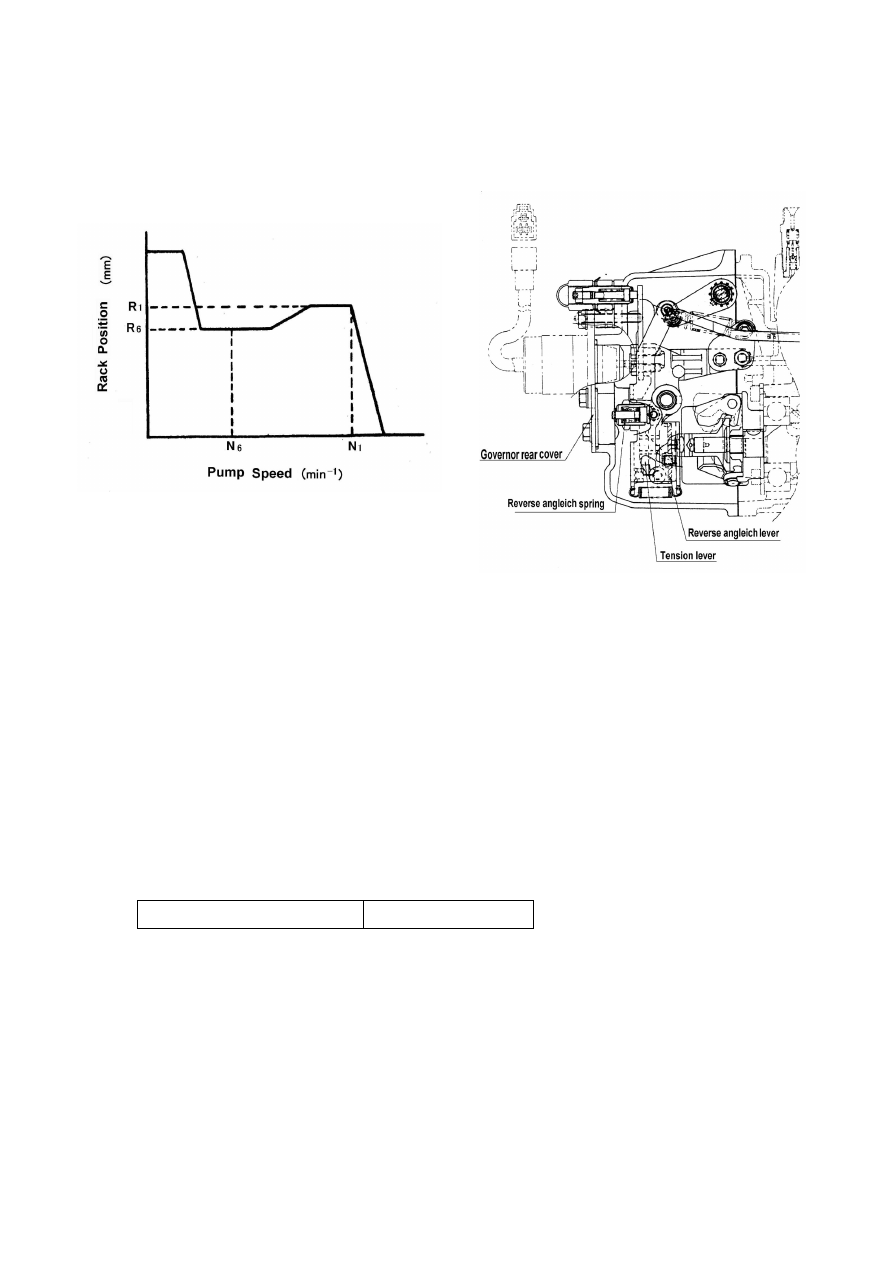
Adjustment of Reverse Angleich 


In the case of the governor with reverse angleich mechanism, use the reverse angleich spring 
in the assembled state.


Adjustment of Reverse Angleich 
Make adjustment of reverse angleich after completing the following processes:


Adjustment of fuel volume limiter bolt 


Adjustment of no-load max, and min. revolutions limiter bolt 


① 

Shift the control lever to the full load position, and maintain the fuel injection pump revolution to the 
specified reverse angleich control revolution number (N

6

).


② 

In this condition, remove the  governor rear cover, and screw the reverse angleich assembly into 
the threaded portion of the tension lever until it hits the reverse angleich


lever. If screwing it in 

additionally, the reverse angleich lever will shift in the direction of fuel reduction. Screw and set it to 
the position of the specified injection quantity (R

6

).


③ 

Tighten the lock nut with specified tightening torque, and attach the governor rear cover.


④ 

Again, increase the revolution of the fuel injection pump to the rated revolution speed (N

1

), check 

that the control rack will change the position of the reverse angleich stroke smoothly, and confirm 
that the rack position (R

1

) and injection volume are within the specified limits.


N-m (kgf-m)

Lock Nut Tightening Torque 

24.5-29.4(2.5-3.0) 


48

4.3.5.  Adjustment of Staring Injection Amount 

① 

Set the engine speed at the starting injection amount adjust 
speed and leave the regulator lever at the position in 2 
above.  

② 

Screw in the starting injection amount adjust bolt and adjust 
it to obtain the specified injection amount.   

③ 

Set the pump speed at 50 min

-1

 and check that the amount 

exceeding the specifications is being injected.   


4.3.6.  Checking the Injection Stop 

Leave the regulator lever at the position as before.   

① 

Checking the Injection Stop: Set the pump speed at the 
speed 50min-1 higher than the no load max. speed, and 
check that the injection amount reduces to zero.   

② 

Checking the Stopping: Set the pump speed at the rated 
speed, turn off the stop solenoid and check that the 
injection amount reduces to zero.   


49

5. Fuel injection Nozzle 

When fuel 0il pumped by the fuel injection pump reaches the injection nozzle

it pushes up the nozzle valve

held down by 

spring

),

and is injected into the combustion chamber at high pressure

.               


The fuel is atomized by the nozzle to mix uniformly with the air in the combustion chamber. How well the fuel is mixed with 
high temperature air directly affects combustion efficiency

engine    Performance and fuel economy


Accordingly, the fuel injection nozzles must be kept in top condition to maintain performance and operating efficiency. 

5.1. Functioning of fuel injection nozzle 

Fuel from the fuel injection pump passes through the oil port in the nozzle holder and enters the nozzle body reservoir. 
When oil reaches the specified pressure

it pushes up the nozzle valve

held by the nozzle spring

),

and is injected 

through the small hole on the tip of the nozzle body


The nozzle valve is automatically pushed down by the nozzle spring and closed after fuel is injected. 
Oil that leaks from between the nozzle valve and nozzle body goes from the hole on top of the nozzle spring through the oil 
leakage fitting and back into the fuel tank. 
Adjustment of injection starting pressure is effected with the adjusting shims. 

5.2. Type/construction of fuel injection nozzle 

There are two types of fuel injection nozzles. Direct injection engines are equipped with the hole type, and indirect injection 
engines with the pintle type. 
The YPD-MP fuel injection pump is designed for use with both direct and indirect injection engines. The hole type/pintle 
type of fuel injection nozzle are used according to the engine type. 


+1.0 (+10) 

Nozzle opening 

pressure 

MPa 
(kgf/cm

2

21.6 

(220) 

(0) 

Nozzle angle 

deg. 

162 

159 

No. of nozzles

×

dia. 

mm 

5

×

0.16 5

×

0.17 

Identification No. 

(Nozzle type) 


162P165VAE1 159P175VAD1 


Nozzle holder 

F.O. return pipe joint 

Hole type fuel injection nozzle 

Nozzle spring

Nozzle spring seat


50


Nozzle body identification number 


The type of nozzle can be determined from the number 


inscribed on the outside of the nozzle body. 

1

Hole type fuel injection nozzles   


5.3. Fuel injection nozzle disassembly 

Note:  


1. Disassemble fuel injection nozzle in a clean area as for fuel injection pump. 
2. When disassembling more than one fuel injection nozzle, keep the parts for each injection nozzle separate for each 
cylinder (i.e. the nozzle for cylinder 1 must be remounted in cylinder 1). 
(1) When removing the injection nozzle from the cylinder head, remove the high pressure fuel pipe, fuel leakage pipe, etc., 
the injection nozzle retainer nut

and then the fuel injection nozzle. 


(2) Put the nozzle in a vise 
NOTE:    Use the special nozzle holder for the hole type injection nozzle so that the high pressure mounting threads are 
not damaged. 


51

3

Remove the nozzle nut 


NOTE: Use a special box spanner for the hole type (the thickness of the two nozzle nuts is 15mm(0.5906in.)). 
(4) Remove the inner parts 
NOTE: Be careful not to loosen the spring seat, adjusting shims or other small parts. 

5.4. Fuel injection nozzle inspection 

5.4.1.  Washing 

1

Make sure to use new diesel oil to wash the fuel injection nozzle parts. 

2

Wash the nozzle in clean diesel 0il with the nozzle cleaning kit. 


(3) Clean off the carbon on the outside of the nozzle body with a brass brush. 
(4) Clean the nozzle seat with cleaning spray. 
(5)Clean off the carbon on the tip of nozzle with a piece of wood.


52

5.4.2.  Nozzle inspection 

1

Inspect for scratches/wear 

lnspect oil seals for abnormal scratches or wear and replace nozzle if the nozzle sliding surface or seat are scratched 
or abnormally worn. 

(2

Check nozzIe sliding 


Wash the nozzle and nozzle body in clean diesel oil

and make sure that when the nozzle is pulled out about half 


way from the body

it slides down by itself when released. 

Rotate the nozzle a little

replace nozzle/nozzle body as a set if there are some places where it does not slide smoothly. 


3) Inspecting stop plate

inter-piece


Check for scratches/wear in seals on both ends, check for abnormal wear on the surface where it comes in contact with the 
nozzle

replace if stop plate is excessively worn. 


4

lnspecting nozzle spring 


Replace the nozzle spring if it is extremely bent

or surface is scratched or rusted


5

Nozzle holder 


Check oil seal surface for scratches/wear

replace if wear is excessive. 


53

5.5. Fuel injection nozzle reassembly 

The fuel injection nozzle is reassembled in the opposite order to disassembly. 

(1) 

Insert the adjusting shims, nozzle spring and nozzle spring seat in the nozzIe holder

mount the stop plate with the pin 

  i nsert the nozzle body/nozzle set and tighten the nut.


(2) 

Use the special holder when tightening the nut for the hole type nozzle as in disassembly. 


5.6. Adjusting fuel injection nozzle 

5.6.1.  Adjusting opening pressure 

    Mount the fuel injection nozzle on the nozzle tester and use the handle to measure injection starting pressure. If it is 
not at specified pressure, use the adjusting shims to increase/decrease pressure

both hole and pintle types). 


Nozzle nut tightening torque 

N-m(kgf-m) 

Hole type nozzle 

39 – 44 ( 4 – 5 ) 


Injection starting pressure 

MPa(kgf/cm

2

19.6 - 20.6 ( 200 – 210 ) 

Injection starting pressure 

21.6 – 22.6 ( 220 – 230 ) 


Ajusting by 0.1 mm results in a change in the injection starting pressure of about 2 Mpa ( 20 kgf / cm

2

 ) 

Remark ) Injection starting pressure changes on enjine specifications. 


54

5.6.2.  Injection test 

After adjusting the nozzIe to the specified starting pressure, check the fuel spray condition and


seat oil tightness.


  (1) Check seat oil tightness 


After two or three injections, gradually increase the pressure up to1.96MPa (20kg/cm

2

before reading the starting pressure   

maintain the pressure for 5seconds, and make sure that no oil is dripping from the tip of the nozzle. 


Test the injection with a nozzle tester

retighten and test again if there is excessive oil leakage from the overflow coupling. 


Replace the nozzle as set if oil leakage is still excessive.   

2

injection spray condition 

Operate the nozzle tester lever once to twice a second and check for abnormal injection. 
 

5.6.2.1.  Hole type nozzles 


  Replace hole type nozzles that do not satisfy the following conditions


  ●

  Proper spray ang1e

(θ)


  ●

  Correct injection angle 

(α)


  ●

  Complete atomization of fuel 

  ●

  Prompt starting /stopping of injection 


55

6. Troubleshooting 

6.1. Troubleshooting of fuel injection pump 

Complete repair means not only replacing defective parts, but finding and eliminating the cause of the trouble as 
well. The cause of the trouble may not necessarily be in the pump itself, but may be in the engine or the fuel 
system. If the pump is removed prematurely, the true cause of the trouble may never be known. Before removing 
the pump from the engine, at least go through the basic check points given here. 
 

Basic checkpoints 


Check for breaks or oil leaks throughout the fuel system, from the fuel tank to the nozzle. 


Check the injection timings for all cylinders. Are they correctly adjusted? Are they too fast or too slow? 


Check the nozzle spray. 


Check the fuel delivery. Is it in good condition? Loosen the fuel pipe connection at the injection pump 

inlet and test operate the fuel feed pump. 

6.2. Major faults and troubleshooting 

Fault 

 Cause 

Remedy 

(1) No fuel in the fuel tank. 

Resupply 

(2) Fuel tank cock is closed. 

Open 

(3) Fuel pipe system is clogged. 

Clean 

(4) Fuel filter element is clogged. 

Disassemble and clean, or 
replace element 

(5)  Air  is  sucked  into  the  fuel  due  to  defective 

connections  in  the  piping  from  the  fuel  tank  to  the 
fuel pump. 

Repair 

(6) Fuel feed pump is damaged. 

Replace 

Fuel not delivered 
to injection pump. 

(7) Fuel freeze. 

Replace  with  a  fuel  for  cold 
weather. 

(1) Defective connection of control lever and accel. rod 

of injection pump. 

Repair or adjust 

(2) Plunger is worn out or stuck. 

Repair or replace 

(3) Delivery valve is stuck. 

Repair or replace 

(4) Control rack doesn't move. 

Repair or replace 

(5)  Injection  pump  coupling  is  damaged,  or  the  key  is 

broken. 

Replace 

(6) Air sucking. 

Bleed air. 

(7) Plunger/Distribution shaft is seized. 

Replace pump. 

(8) Tappet is seized. 

Replace pump. 

(9) Stop solenoid is damaged. 

Replace 

(10) Cold start device is damaged. 

Replace 

(11) Low cranking speed. 

Replace battery. 

(12) Governor is damaged. 

Replace 

(13) Barrel crack 

Replace pump. 

1. Engine   

won't start. 

Fuel delivered to   
injection pump. 

(14) Transmission shaft is seized. Gear slip. 

Replace 


56


(1) Nozzle valve doesn't open or close normally. 

Repair or replace 

(2) Nozzle seat is defective. 

Repair or replace 

(3) Case nut is loose. 

Inspect and tighten 

(4) Injection nozzle starting pressure is too low. 

Adjust 

(5) Nozzle spring is broken. 

Replace 

(6) Fuel oil filter is clogged. 

Repair or replace 

(7) Excessive oil leaks from the nozzle sliding area. 

Replace the nozzle assembly

(8)  Deformation  due  to  excessive  tightening  of  nozzle 

retaining bolt. 

Replace or adjust. 

Nozzle 

doesn't 

work. 

(9) Strainer is clogged. 

Replace or clean 

(1)  Injection  timing  is  retarded  due  to  failure  of  the 

coupling. 

Adjust 

(2) Camshaft is excessively worn. 

Replace camshaft 

(3)  Roller  tappet  incorrectly  adjusted  or  excessively 

worn. 

Adjust or replace 

(4) Plunger is excessively worn. 

Replace plunger assembly 

(5) Bad installation of injection pump. 

Adjust. 

(6) Air sucking. 

Bleed air. 


Injection timing is 
defective. 

(7) Delivery valve is defective. 

Replace. 

(1) Fuel pipe is cogged. 

Clean 

(2) Fuel filter is clogged. 

Disassemble and clean, or 
replace the element. 

(3) Improper air-tightness of the fuel pipe connection,   

or pipe is broken and air is being sucked in. 

Replace packing; repair pipe

(4) Insufficient fuel delivery from the feed pump. 

Repair or replace. 

(5) Trochoid pump is defective. 

Replace. 

(6) Air sucking. 

Bleed air or hose check. 

(7) Electromagnetic feed pump is clogged. 

Replace. 

(8) Out of fuel. 

Fill the fuel. 

(9) Stop solenoid is defective. 

Replace. 

2. Engine starts,   

but immediately stops. 

(10) Accumulator is abnormal. 

Replace. 

(1)  Knocking  sounds  caused  by  improper  (too  fast) 

injection timing. 

Inspect and adjust 

(2)  Engine  overheats  or  emits  large  amount  of  smoke 
due to improper (too slow) injection timing. 

Inspect and adjust 

(3) Insufficient fuel delivery from feed pump. 

Repair or replace 

(4) Torochoid pump is defective. 

Replace. 

(5) Type of fuel is incorrect. 

Check and refill proper fuel.

Defective 
injection   
timing,  and  other 
failures. 

(6) Fuel tempererture is high. 

Cool. 

(1) Case nut loose. 

Inspect and retighten 

(2) Defective injection nozzle performance. 

Repair or replace nozzle 

(3) Nozzle spring is broken. 

Replace 

Nozzle 
movements 
  is defective 

(4) Excessive oil leaks from nozzle. 

Replace nozzle assembly 

(1) Max. delivery limit bolt is screwed in too far. 

Adjust 

(2) Plunger is worn. 

Replace 

(3) Injection amount is not uniform. 

Adjust 

(4) Injection timings are not even. 

Adjust 

(5) The 1st and 2nd levers of the governor and the control rack 

of the injection pump are improperly lined up. 

Repair 

(6) Delivery holderr is loose 

Inspect and retighten 

(7) Delivery packing is defective. 

Replace packing 

(8) Delivery valve seat is defective. 

Repair or replace 

(9) Delivery spring is broken. 

Replace 

(10) Carbon deposit is adhered. 

Clean 

(11) Spray pattern is abnormal. 

Replace 

(12) Nozzle crack. 

Replace 

3.Engine's 

output 

is 

insufficient. 

Injection pump is   
defective. 

(13) Plunger barrel crack. 

Replace fuel injection pump.


57


(1) Movement of central rack is defective. 
1) Stiff plunger movement or sticking. 

Repair or replace 

2) Rack and pinion fitting is defective. 

Repair 

3) Movement of governor is improper. 

Repair 

4) Delivery holder is too tight. 

Inspect and adjust 

(2) Uneven injection volume. 

Adjust 

(3) Injection timing adjustment failure. 

Adjust 

(4)  Plunger  is  worn  and  fuel  injection  adjustment  is 

difficult. 

Replace 

(5) Governor spring is too weak. 

Replace 

(6) Feed pump can't feed oil at low speeds. 

Repair or replace 

(7)  Fuel  supply  is  insufficient  at  low  speeds  due  to 

clogging of fuel filter. 

Disassemble and clean, or 
replace element 

(8) Weight abnormality. 

Replace 

(9) Shifter is worn. 

Replace governor. 

(10) Air sucking. 

Check piping. 

(11) Torochid pump is defective. 

Replace 

4. Idling is rough. 

(12) Governor is worn. 

Replace or adjust. 

(1) The wire or rod of the accel is caught. 

Inspect and repair 

(2) Control rack is caught and can't be moved. 

Inspect and repair 

5.  Engine  runs  at  high  speeds, 

but cuts out at low Speeds. 

(3) Low idling stopper bolt is abnormal. 

Replace or adjust. 

(1) Governor spring is broken or excessively worn. 

Replace 

(2) Injection performance of nozzle is poor. 

Repair or replace 

(3) Trochiod pump is defective. 

Replace 

(4) Accumulator is abnormal. 

Replace 

(5) Filter and pipe are clogged. 

Check piping. 

6.  Engine  doesn't  reach  max, 

rpm. 

(6) Governor is abnormal. 

Replace 

(1) Injection timing is too fast or too slow. 

Adjust 

(2) Injection from nozzle is improper fuel drips after each 

infection. 

Adjust 

(3) Injection nozzle starting pressure is too high. 

Adjust 

(4) Uneven injection. 

Adjust 

7. Loud knocking. 

(5) Engine overheats, or insufficient compression. 

Repair 

(1) Injection timing is too fast. 

Adjust 

(2) Air volume intake is insufficient. 

Inspect and repair 

(3) The amount of injection is uneven. 

Adjust 

When exhaust   
smoke is black: 

(4) Injection from nozzle is improper. 

Repair or replace 

(1) Injection timing is too slow. 

Adjust 

(2) Water is mixed in fuel. 

Inspect  fuel  system,  and 
clean 

(3) Shortage of lube oil m the engine. 

Repair 

8.Engine 
exhausts  too 
much smoke. 

When exhaust   
smoke is white: 

(4) Engine is over-cooled. 

Inspect 


58

7. Tightening torques for main bolts and nuts

7.1. Pump part 

59

7.2. Mechanical governor part 

60

8. Tools

Name of tool 

Shape and size 

application 

Nozzle plate 
158090-51700 

Bottom clearance gauge 

158090-51800 : MP2 
158090-51810 : MP4

Plunger SP seat extractor 

158090-51900

Bottom clearance gauge 

Bottom clearance gauge 


Content      ..     64      65      66      67     ..