Takeuchi compact excavator TB125, TB135, TB145 / diesel TNE / diesel Yanmar. Service Manual - page 65
 

  Index      Manuals     Takeuchi compact excavator TB125 (12510003~), TB135 (13510004~), TB145 (14510004~) / diesel TNE / diesel Yanmar. Service Manual


Search            copyright infringement  


Content      ..     63      64      65      66     ..


Takeuchi compact excavator TB125, TB135, TB145 / diesel TNE / diesel Yanmar. Service Manual - page 65


31


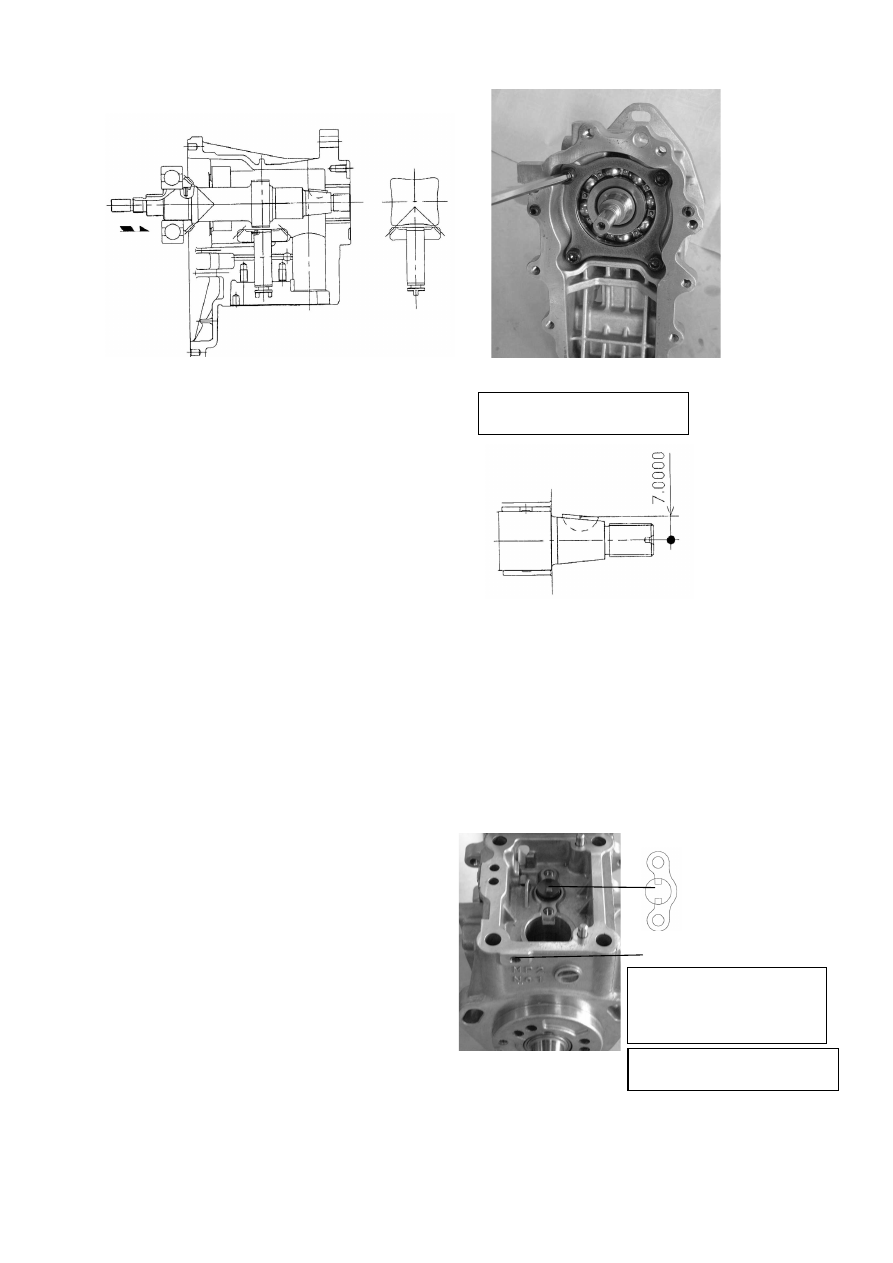
Install the camshaft.


Attaching camshaft 


Apply molybdenum disulfide to the bushing or the

bearing. 


Insert the camshaft into the pump body with

transmission shaft CMP at the lowered position
(gear B touching the pump body). 


Be careful that the cam and gear B do not interfere

with each other. 


(Especially for 4 cylinder engine, note that the

phase in which the cam passes is limited.) 


The shaft can be inserted with the key of the

driving side press-fitted to the camshaft. 
Be careful not to damage the camshaft bushing. 


Tightening Torque : 8-10 N-m 

Checking backlash 


Rotate camshaft to check that transmission shaft

rotates smoothly. 


Fix transmission shaft from upper surface of the

housing, and turn the camshaft to check the backlash. 
Backlash must be in the range from 0.2 to 1.5 degree. 

Note: 

When measuring at the position of camshaft

driving side key (at the center of the key as shown below),

the displacement must be in the range from 0.03 to 0.25. 

Position the transmission shoe of the

transmission shaft CMP as shown in the

illustration.


Tightening Torque : 79-84 N-m 

Tighten the rack plug. (If rack
plug has been removed.)


Rack plug 


32


Position the camshaft key groove as shown in the 
illustration.


Install the removal stop, (transmission shaft). 


Fasten the removal stop, (transmission shaft).


Engagement of gears 

  With the phase of camshaft and collar of transmission shaft set in the direction as shown below, engage gears 

A and B with each other. (Check that the match mark of gear B and the mark of gear A shown below are 

aligned with each other by looking through the feed pump installation hole.) 

  When inserting the stopper pin, do not raise the transmission shaft excessively, or the gears will be 

disengaged. (Check the engagement again after inserting the stopper pin.) 

  The positions of the collars of transmission shaft are not limited only if either one is at the top or bottom as 

shown. 

Tightening Torque : 8-10 N-m 


33


Install the whirl-stop, (tappet). 


Install the governor weight CMP and nut, (governor support).


Fasten the nut, (governor support), (and provide the whirl-stop 
to the cam shaft.) 


Install the feed pump.


Install the tappet.   
Direct the tappet’s whirl-stop groove as shown in the
illustration.


Whirl-stop groove


Assembling tappets 


Insert tappet into the pump body with the slit

directed toward the lock side, and attach the
tappet lock. (T = 4 to 5 N

m) 


Turn the camshaft to check that the tappet

moves up and down smoothly. 

Tighten the tappet, while moving it upward and
downward.


Identification hole (

φ

3, depth 2 mm)

Identification of feed pump

Spec. 

φ

3 identification 

hole 

General 

purpose 

Not provided 

TK Provided 


Note that the identification hole can be seen only when

looking from obliquely above because it is located on the

pump case side.


Tightening Torque : 79 - 84 N-m 


34


3.3.3.    Install the hydraulic head CMP. 


  Install the hydraulic head CMP.


Install the joint, (transmission shaft).


Assemble the FIC adjust shim inside the tappet. 


Install the hydraulic head CMP. 


Install the hydraulic head CMP fastening bolt. 


Insert the two positioning pins.    Be sure not to confuse 
packing front with rear surface.    (Align them with holes 
on the body.) 

While hand pressing the hydraulic head, temporarily
tighten the tightening bolts.  Then, tighten them
with specified torque.


Installing H head 


Assemble shims with an appropriate thickness that

corresponds to the measurement of the bottom
clearance (refer to attached drawing 3).   


Temporarily tighten the hexagon socket head bolts

evenly in the order as shown below until the surfaces of
H head and pump body contact with each other, and
subsequently tighten to the specified torque in the same
order. 


After assembling H head, check the top clearance

again. 


After assembling H head, push the rack from governor

side to check that the rack is returned with the force of
rack auxiliary SP. 


When reassembling H head, be sure to replace the

head packing with new one. 

Important 

Tightening Torque : 18-22 N-m 

Tighten the bolts in diagonal order, while checking the

torque with torque meter.


35


Measure the plunger top position.


3.3.4.  Assembling the Hydraulic Head 


Install the accumulator.


Install the spring, (accumulator).


Install the plug with new seal washer, (accumulator).


Install the distribution shaft. 


Direction of fixed flange (camshaft keyway) 

(As viewed from driving side) 


Direction of distribution shaft longitudinal 

groove 

(As viewed from upper side 


Bottle clearance adjustment should refer to Page 59. 

Attaching accumulator 


Be sure to install the piston in the correct

direction. 


Make sure that the piston can slide smoothly. 

Inserting distribution shaft 

  Insert distribution shaft so that the directional 

relationship between the shaft and camshaft is as 

shown below (Do not assemble upside down). 

  Use the following drawing simply as a reference 

because the component can be inserted in either of

two orientations. 

  Insert the component securely into the distribution

shaft joint until it is sunk below the end surface of

the distribution shaft sleeve. 


Upper side


Lower side


Camshaft keyway

O

perati

ng

 si

de


Anti-o

peratin

g si

de


Flange cutout


Anti-o

peratin

g si

de


O

perati

ng

 si

de


Governor side


Driving side


Distribution shaft longitudinal groove, 

cut off surface


36


Install the plug, (distribution shaft).


Fasten the plug, (distribution shaft). 


Install the plug with new copper packing, (barrel).


Fasten the plug, (barrel). 


Install the new packing, (delivery valve seat).


Install the delivery valve CMP. 


Install the spring, (delivery). 


Install the holder, (delivery). 


Tightening Torque : 10-15 N-m 

Tightening Torque : 30-35 N-m 

Holder(delivery

Spring(delivery

Valve(delivery

Seat(delivery

Packing(delivery

Returnspring

Returnvalve (φ2)

Spring seat(return valve

Tightening Torque : 40-45 N-m 


37


Install the new packing, (timer).


Install the holder with new O-ring, (timer).


Fasten the holder, (timer).


Install the thermo-element with new O-ring.


C.W.plug  

Seal washer

O-ring P14 

Piston(thermo-e
lement)  

Timer holder 

Damper ring 

Timer packing 

O-ring JASO 1011 

O-ring P15 
(Hardness 90   

Spring  

O-ring(JASO 1020) 

Timer piston  

O-ring(JASO 1020) 

Thermo-element 


Do not forget to assemble the timer packing,
(at holder bottom).   


Do not forget to assemble the damper ring.   


Take care not to use O-rings with
inappropriate sizes. 

Check that the timer piston moves smoothly in
the timer holder hole (clearance: 4-8 micron m).


Before installing the thermo-element, press
down the piston with the timer holder being
installed to the head, (T=40-45N.m), and
check that the piston returns up through the
spring load.     


The standard thermo-element release
temperature shall be 5-8 degC(41-46.4 degF). 
(Thermo-element released at 15-18 degC (59-
64.4 degF) is available as option.   
  Take care not to mistake the specifications:
see diagram below.) 


Do not pull out the piston housed in the
thermo-element manually.  If it is extracted
manually, discard it since the re-use of the
piston is no longer possible.   


Do not tighten the thermo-element with
excessive tightening torque, (T=30-35N.m). 


Do not tighten t he cooling water plug with
excessive tightening torque, (T=22-25N.m).   


Take care not to catch impurities in the seal
washer.  


Thermo-element for 

15~18 

degC


Identification groove 

JASO : Japanese Automobile Standard


38


Fasten the thermo-element.


I

nstall the joint, (C.W), and he plug, (C.W.)


Fasten the plug, (C.W.) 


Install the joint, (overflow) and the joint, (overflow). 


Install the joint, (FO inlet).


Installation position of Joints


Tightening Torque : 30-35 N-m 

Assemble the seal washers, taking care not the washer 
stride over steps.    (One seal washer is required for 
respective upper and lower portions.) 


F.O. valbe  
return pipe 

Cooling water

F.O. outlet 

F.O. inlet 

Direction of pipe depends on respective specifications. 


39

3.4. Re-assembling the Governor


Governor Body Parts 


Pierce the governor lever CMP and shim through the governor 
lever shaft and assemble.


Fit the governor lever shaft with the removal stop, (governor 

lever shaft) and fasten the removal stop bolt


Install the shim to the shaft, (control lever).


Install the regulator lever. 


Pierce the spring, (control lever) through the lock nut, (control 
lever) and fasten it to the thread of the shaft, (control lever). 


Fasten the nut, (control lever).


Governor Lever CMP End Float Adjust Shim


Measure the side clearance of the tension lever with 
thickness gauge. 
Standard: 0.3 to 0.6 mm (adjusting with shim) 


Tightening Torque : 19.6-24.5 N-m

Measure the side clearance with thickness gauge. 
Standard: 0.3 to 0.6 mm (adjusting with shim) 


40

3.5. Combining Governor and 

Pump Bodies


Install the new packing.


Turn the link lifter plate counterclockwise. and install the 
governor body to the pump bodies 


Do not confuse front with rear surface.    Assemble it,
while aligning bolt holes with those on the body.


Rack


a) During assembly


b) During operation


Link lifter


Link


Attaching governor CMP 

 Be careful not to bend or damage the governor case packing (GRC). (It is not reusable. If it 

sticks to the packing surface, remove it without giving damage to the surface of the packing.) 

 Direct the link lifter as shown in Fig. a) shown below, where the semicircular section is 

positioned at the lower side, and bring governor CMP to the pump body until the link comes 

into contact with the rack. 

  At this time, be careful that the link does not hit the pump body. (If the link hit the pump body 

severely, check that the link is not bent or deformed.) 

 Direct the link lifter as shown in Fig. b) shown below, where the semicircular section is 

positioned at the upper side, and engage the rack and the link with each other. 

  At this time, if it is difficult to engage the rack and the link with each other, assemble them while 

pushing the governor lever to the decreasing side (when mechanical governor is used). 

 After putting the link lifter in the state shown in Fig. b), pull the governor CMP a little to check 

that the link and rack are engaged with each other. (Be sure not to pull governor CMP 

excessively).  

  (If the barrel plug is not installed yet, the following method can be used to check the

 plunger 

rotation. 

  Mechanical governor: Push the governor lever to the decreasing side through the solenoid 

attaching hole. 

  New ECO governor: Push the rack to the increasing side through the rack inspection port.) 

 Be sure to tighten the link lifter securing bolt. (T = 8 to 10 N 

-


m) 


41


Insert the governor link into the link hole of the pump body.


Fit the link lifter to the installation hole and fasten the bolt. 


Pull the governor assembly slightly to check that the link is 
engaging securely. 
Combine Governor and Pump Bodies 


Install the new O-ring to the stop solenoid and assemble them 
to the governor case.


nstall a new packing, (governor case cover) to the case.


Install the governor case cover to the case.


This completes reassembly of the pump. 


Tightening Torque : 7.8-9.8 N-m 


42

4. Adjustment of Fuel Injection Pump and Governor 

Adjust the fuel injection pump after you have completed reassembly. The pump itself must be readjusted with a special 

pump tester when you have replaced major parts such as the plunger assembly, roller guide assembly, fuel camshaft, etc. 

Procure a pump tester like the one illustrated below. 


4.1. Preparations 

Prepare for adjustment of the fuel injection pump as follows: 

(1) 

Adjusting nozzle assembly and inspection of injection starting pressure. 


(2) 

Adjusting injection pipe


(3) 

Mount the fuel injection pump on the pump tester platform. 


Mpa (kgf/cm

2)


Adjusting nozzle type 

YDN-12SD12


Injection starting pressure 

16.2 – 17.2(165 – 175)


mm 

Inner dia./outer dia.  ×  length 

Ф

2.0/Ф6.0  ×  600 

Minimum bending radius 

25 


43


(4) 

Remove the plug in the oil fill hole on the top of the governor case, and fill the pump with about 200cc of pump oil or engine 
oil. 


(5) 

Complete fuel oil piping and operate the pump tester to purge the line of air. 

(6) 

Set the pressure of oil fed from pump tester to injection pump at 19.6-29.4kPa(0.2-0.3kgf/cm

2

 ) ,temp. at 40

±

2 degC(104

±

3.6 degF) 


44

4.2. Bottom clearance adjustment(Fuel Injection Timing) 

1.  The Fuel Injection Timing of MP-pump is made by means of 

adjusting the bottom clearance of the Cam ie. adjustment of the 
Pre-stroke of the plunger , as follows. 

2.  The adjustment of the clearance shall be made at cam-top 

position in order to get the reliable     and easier method. 
Therefore herein after we will mention that “The adjustment of 
the bottoms clearance (of the Cam)”. 

3.  First of all , put the JIG of the bottom clearance measurement 

on the standard gauge(W/”A”- measurement). Then set the 
O-point of the dial gauge. 

4.  Next adjust the clearance by shims into the standard after 

measuring the bottom clearance A* with JIG (Dial gauge)(Refer 
to the attached sheet)*Measurement between upper surface of 
the Barrel and upper surface of the plunger at Cam bottom 
position 


Dial gauge

A

Bottom clearance gauge


A

Shim

Plunger

Barrel

Bottom clearance gaug


45

4.2.1.  The bottom clearance adjusting value and the Cam classification 


Cam shaft


Cam speed 

3 cylinder 

4 cylinder 

Plunger bottom 

Clearance (dimension: A) 

(mm)


Standard shim 

thickness (mm)


1.1 m/s 

158552-51020

158553-51020

25.5±0.05 

1.3 

1.3 m/s 

158552-51030

158553-51030

25.9±0.05 

0.9 

MP2 

1.7 m/s 

158552-51040

158553-51040

26.3±0.05 

0.8 

1.8 m/s 

123907-51040

2.1 m/s 

129906-51040

MP4 

2.3m/s 


129907-51040

25.55±0.05 

1.05 


Shape of    cam shaft end 


Cam Speed 


MP2 MP4 


1.1m/s 2.3m/s 


1.3m/s 2.1m/s 


1.7m/s 1.8m/s 


46

4.3. Adjustment of Governor 

4.3.1.  Adjustment of No Load Max. Engine Speed 

Set the engine speed at the no load max. speed.    Pull the regulator 
lever and adjust the max. speed limit bolt to obtain the specified 
injection amount.    Fasten the nut after completing the adjustment.   


4.3.2.  Adjustment of Fuel Limit Bolt 

  The MP2 pump has the lift adjustment FO limiter as a standard 

equipment.    Screw in the lift adjustment screw fully, then return 
the screw by 0.5 turns and fasten the screw with the lock nut.    (In 
the specifications where no torque control spring is used, keep the 
lift adjustment screw completely free.)   

  Set the pump speed at the rated speed and move the regulator 

lever until it contacts the maximum speed limit bolt.   


Check that the amount being injected exceeds the rated injection 
amount, screw in the fuel limit bolt and adjust the injection amount.


4.3.3.  Adjustment of Torque-Rise Point 

The Torque-Rise adjustment comprises the FO limiter (torque spring) and the torque control spring.   

  Set the pump speed at the Torque-Rise speed and leave the 

regulator lever at the position in 2 above.   

  When both of the FO limiter and torque control spring are used:   


Screw in the torque control assembly, adjust to obtain the 
specified injection amount and fasten the lock nut.   

  Specifications of Only the FO Limiter 


Screw in lift limit bolt of the FO limiter, adjust to obtain the 
specified injection amount and fasten the lock nut.   


Adjustable lift torque spring 


Content      ..     63      64      65      66     ..