Takeuchi compact excavator TB125, TB135, TB145 / diesel TNE / diesel Yanmar. Service Manual - page 64
 

  Index      Manuals     Takeuchi compact excavator TB125 (12510003~), TB135 (13510004~), TB145 (14510004~) / diesel TNE / diesel Yanmar. Service Manual


Search            copyright infringement  


Content      ..     62      63      64      65     ..


Takeuchi compact excavator TB125, TB135, TB145 / diesel TNE / diesel Yanmar. Service Manual - page 64


15


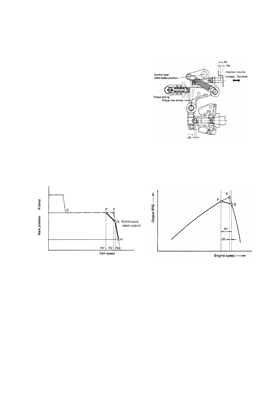
(6) Necessity of torque spring and function 

Engines used in construction machinery are subjected


to sudden loads which cause a decrease in speed and 

sometimes results in stopping of the engine. A torque


spring is provided to move the control rack towards 

injection volume increase when engine speed decrease


to increase torque to withstand overloads, and in turn


prevent the engine from stopping. 

The governor control lever is fixed at point G in the 

diagram below, the continuous rated output position. 

At this time

when engine is loaded, the tension lever 

encompasses the torque spring, the control rack comes 

away from full load stopper, and fluctuates between G 

and H according to engine load. 

When the load on the engine exceeds the continuous 

rated output, speed decrease, governor spring tension 

exceeds the governor weight thrust load and 

overcomes the torque spring set load. The tension lever 

then gradually causes the control rack to move towards 

injection volume increase via the governor lever and 

link, and the torque rise stroke ends when the control 

rack reaches F'. 


The torque spring thus provides for increasing of injection volume when speed decrease, to increase engine torque and in 

turn prevent engine stopping due to sudden increases in load, and also provide for strong engine output characteristics. 


16


(7) No load max. speed 

When the load decreases from full load max. speed 

and engine speed further increase, the increased thrust 

load of the governor weight acting on the governor 

spring through the tension lever exceeds the set load of 

the spring, the tension lever and governor lever 

descend clockwise, the control rack is pushed to the no 

load injection volume position (RH), and the engine is 

operated at no load max. Speed. 

When the engine is being used at partial load, the 

governor spring functions in the same way at a lower 

speed (i, i'-j) as for full load max. Speed, as the 

governor spring set load is smaller. 


(8) Stopping engine 

The engine stops when you turn the governor control lever all the way towards stop. 

On engine equipped with a stop device, the engine can be stopped by moving the control rack to the stop position, 

regardless of the control lever position. 


17

2.4.3.  Delivery Part 

Delivery Ports and Cylinder Number 


4MP2, 4MP4 

Cylinder No.


1 

2 

3 

4 

Port No.


Injection Order


Flywheel side 

1

2

3

4

Driving side 

3MP2


Cylinder No.


Port No.


A

Injection Order 

Flywheel side 

Driving side 

1

2

3


18

2.5. Function of Component 

2.5.1.  F.O. Feed Pump 

The FO feed pump feeds fuel oil from the fuel tank to the fuel injection pump via the water separator and fuel filter. 

The trochoid FO feed pump, installed on the fuel injection pump side, is driven by the fuel camshaft via the bevel gear. 

This feed pump can feed high pressure fuel oil into the FO injection pump, but while the fuel oil inside the piping is empty 

due to shortage of gases, etc., the pump’s self-feeding performance is low.    Accordingly, the manual priming pump with 

FO filter or solenoid pre-feed pump is used together. The feed pump failure causes the delivery pressure and volume to 

drop. This, in turn, shortens the service life of the fuel injection pump and causes the pump to become faulty. 

Replace the feed pump assembly after 10,000 hours’ use as a standard. 


FO feed pump 

⑪ 

Relief valve 

⑫ 

Spring  

⑬ 

Seal washer 

⑭ 

Relief plug 

⑮ 

Bolt  

⑯ 

C-ring  

⑰ 

Bush  

⑱ 

Thrust washer 

⑲ 

Washer 

① 

Pump case 

② 

Pump cover 

③ 

Inner rotor   

④ 

Outer rotor 

⑤ 

Shaft 

⑥ 

Molded ring 

⑦ 

Oil seal 

⑧ 

Bevel gear 


⑩ 

Drive pin 


19

2.5.1.1.  Specifications of F.O. Feed Pump 


Outlet orifice dia. :

φ

0.7mm 

F.O. grade     : ISO 8217 

Revolutions    : 1000min

-1


F.O. temp.          : 40 degC (104 degF) 


2.5.1.2.  Inspection of F.O. Feed Pump


(1)  Check for the abnormal flaws and chipping on the bevel gear face.    If found to be abnormal, replace the whole feed pump 

assembly.  
 

(2)  Check for the abnormal flaws or wear on the face contacting with the pump case, pump cover, inner rotor and outer rotor.   

If wear exceeds 0.1mm, replace the whole feed pump assembly.   
 

(3)  Check for the abnormal wear of the shaft and oil seal moving area.    If wear exceeds 0.05mm in depth, replace the whole 

feed pump assembly.   
 

(4)  When no abnormality was found, just replace the molded ring and seal washer and re-assemble.   


(5)  After install the fuel injection pump, operate the fuel injection pump to check that no oil leaks from each part.   


YPD-MP2 YPD-MP4 

Suction Head   
     

(k

P

a)


-10 

Std. Delivery Pressure 
   

MP

a)


0.4-0.5 0.6-0.7 

Std. Delivery Volume 
   

cm

3

/min


500 600 


Pressure & delivery volume figures at conditions below: 

Conditions:


20

2.6. Timer Mechanism 


When the engine is used in a wide range from low to high speeds, it is necessary to change the fuel injection timing 

according to the engine speeds for always keeping the optimum firing timing.  It is also necessary to optimize the 

injection timing for reducing noise and exhaust gas emissions.   

This pump has the timer mechanism for revolutions, load and cold starting.   


2.6.1.  Structure and Functions 

The engine speed timer is the mechanical timer which uses the oil leakage from the small diameter sub spill port installed 

slightly upper side of the main spill port of the jerk pump.    When the engine speed is high, pressure rises before oil leaks 

from the small diameter port and injection is started.    But when the engine speed is low, pressure does not rise until the 

port blocked by the plunger and the injection start is delays.    Usually, the lower the engine speed, further the injection 

timing advances.    But this engine speed timer prevents the injection timing from advancing during the low engine speed 

ranges and thus the noise and Nox. emissions can be controlled.   


The fewer the injection amount, the earlier the load timer causes the main port to close by the plunger’s upper lead for 

advancing the injection timing. This feature is instrumental in preventing misfire or emission of bluish white smoke during 

low load operation.   


The cold start timer causes the sub port to be blocked only under cold temperatures for accelerating injection timing and 

facilitating in cold starting. The timer houses the thermo element and cooling water circulates around the temperature 

sensing section. The thermo-element senses the coolant temperature for adjusting the control piston. The sub-port is 

blocked when the temperature is lower than the set temperature and the pressure is raised earlier than in the normal 

temperature for advancing the injection timing.  When the temperature exceeds the set temperature, the sub-port is 

opened and the regular injection characteristics are recovered.       


Pump speed

Advance

In

je

ct

io

n

 T

im

in

g

Retard

At no load

At full load

At cold start

Rated

C : Thermo

-element

Main Port

Plunger

Barrel

Timing Control

Device

Piston

.

Coolant

Main Lead

B : Sub Lead

A :Sub Port

Improving cold startability

Reduction of noise & NOx

Reduction of white smoke

Required characteristics

Required characteristics

Hydraulic control device of  injection timing

Hydraulic control device of  injection timing

(Speed timer,Load timer,Cold start timer)

(Speed timer,Load timer,Cold start timer)


21

2.7. C.S.D.(Cold Start Device) 

2.7.1.  Cold Starting Advancer 

Purpose 

In order to facilitate easy engine starting under cold temperatures, the advancer senses the cooling water temperature for 

advancing the fuel injection timing.   


2.7.1.1.  Structure & Function 


At normal operating

At cold starting

Engine coolant

Termo-elementt

 Piston

 Spring

Fuel gallery

Plunger

Plunger  barrel

Main port

Sub port

When the coolant temperature is higher than specified
value, the thermo-element keeps expanding and the sub-
port is opened.

Fuel IN

Sub-port
is opened

Fuel IN

Sub-port
is closed

When the coolant temperature is lower than specified
value, the thermo-element keeps shrinking and the sub-
port is closed by piston.


22

3. Disassembly  ,Reassembly 

and Inspection


3.1. Disassembly


3.1.1.  Separating  the  pump  body  from  the 

governor body 


Install the pump body to the disassembly table. 


Remove the link lifter fix bolt.


Turn the link lifter plate counterclockwise. 


Rotating the link lifter will move the inside link 
upward/downward, so the control rack may be 
engaged/disengaged.


Remove the bolt fixing the pump and governor bodies.


Separate the governor from the pump body. 


The pump body separated from t he governor body


Disassembled parts must be put aside in order. 
Wash them before reassembly. 

Link insertion window


23

3.1.2.  Separating the governor weight CMP 


Providing whirl-stop to the camshaft 


Example of whirl-stop


Remove the nut, (governor support).


3.1.3.  Disassembling the hydraulic head 

Disassembling the hydraulic head


Remove the joint, (FO inlet pipe). 


Disassembling the delivery valve 


Remove the holder, (delivery).


Remove the delivery valve and gasket. 


Remove the delivery valve and gasket. 
Remove gasket


Delivery valve parts disassembled. (Take care not
to mix these with other parts on reassembly.
Reassemble these to the original port as a set.) 


24


Remove the distribution shaft.


Removed parts must be stored in the cleaning oil sump.


Remove the plug and gasket, (barrel). 


Remove the plug, (C.W.) and the joint, (C.W.) 


Parts disassembled.


Remove the thermo element. 


Remove the holder and gasket, (timer)   


Remove the plug, (accumulator).


Make sure that the seal washer remains on the plug.


25

3.1.4.  Separating hydraulic head CMP 


Remove the hydraulic head CMP fixing bolt.


Remove the hydraulic head CMP.


Remove the packing. 


3.1.5.  Separating the cam shaft 


Remove the joint, (distribution shaft).


Remove the feed pump. 
Do not loosen two bolts (A)


.


Remove the removal stop, (transmission shaft) fastening bolt. 


O-ring 

Make sure that two O-rings are free from 
damages. 


26


Remove the whirl-stop, (tappet)


Take out the tappet


Tappet disassembled and FIC adjust shim.


Remove the retainer, (bearing) fastening bolt. 


Remove the retainer, (bearing).


Lift the transmission shaft slightly by your hand.


Align the camshaft’s key groove with the embossed mark on 
the body.


Lift the transmission shaft a little and pull out the camshaft.


Camshaft extracted


Remove the transmission shaft CMP.


27


Remove the transmission shaft CMP. 

3.1.6.  Disassembling the hydraulic head CMP 


Compress the plunger spring and remove the   

spring retainer, (B). 


While compressing the plunger spring using special service 
tool, remove spring retainer B. 


Remove the rack return spring.


Remove the rack guide fastening bolt.


Remove the rack guide. 


Remove the spring retainer.


Remove the control sleeve.


Remove the plunger. 


Parts removed from hydraulic head CMP


Disassembled parts must be separately stored in the cleaning 
oil sump.


Cleaning oil sump 

Cleaning oil sump 

Plunger SP seat extractor 

Spring retainer B. 

Hydraulic head 


28

3.2.   Disassembling the Governor


Remove the lock nut, (Control lever). 


Remove the regulator lever. 


Remove the shim. 


Remove the removal stop, (governor lever shaft) fixing bolt. 


Remove the removal stop, (governor lever shaft). 


Pull out the governor lever shaft. 


Removed governor lever shaft


Take out the governor lever CMP.


Remove the spring.   


29

3.3. Reassembly


3.3.1.  Re-assembling the hydraulic head 


Install the plunger.


Install the control sleeve and spring retainer. 


Install the rack guide.


Identification marking


Ball


Upper lead


Sub-lead


Note that the positional relationship of the upper

lead and sub-lead of the plunger and the ball of
the control sleeve is as shown below. (Plunger
identification marking (such as "W4") and the ball
of the control sleeve are oriented in the same
direction.) 


Be careful that the plunger is NOT inserted

upside down. 

Rack guide


Control sleeve


Rack auxiliary SP


Rack


Distribution shaft sleeve


Upper spring retainer


L

Attaching rack and rack guide 


When installing rack guide, push it against the

distribution shaft sleeve and upper spring retainer so
that the rack is in parallel with the direction of
camshaft. (T = 3 to 4 N

m) 


Movable range of rack is to be equal to or larger

than 

±

7 mm. 


Fix the rack at the position of L = 25, and measure

the effective stroke and sub-step (overflow stroke) to
check that they are within the standards (Refer to
attached drawing 1.) 


The rack must not separate from the ball of the

control sleeve within the movable range. 


Fix the plunger with a jig and measure the total

backlash. (To be equal to or less than 0.2 mm) 


The load of rack auxiliary SP must be able to return

the rack from the maximum decreased position to
the maximum increased position). 


30


Install the rack guide fastening bolt.


Install the plunger spring and spring retainer (B).


3.3.2.  Re-assembling Cam Shaft 


Install the transmission shaft CMP. 


Install the camshaft. 


Tightening Torque : 3.9-4.9 N-m 

Spring retainer (B).

Spring.


Attaching transmission shaft CMP 


Apply molybdenum disulfide to the shaft section. 


Check that the transmission shaft rotates


Content      ..     62      63      64      65     ..