Takeuchi compact excavator TB125, TB135, TB145 / diesel TNE / diesel Yanmar. Service Manual - page 39
 

  Index      Manuals     Takeuchi compact excavator TB125 (12510003~), TB135 (13510004~), TB145 (14510004~) / diesel TNE / diesel Yanmar. Service Manual


Search            copyright infringement  


Content      ..     37      38      39      40     ..


Takeuchi compact excavator TB125, TB135, TB145 / diesel TNE / diesel Yanmar. Service Manual - page 39


V-23

TROUBLESHOOTING

SLEWING

TB125, 135, 145

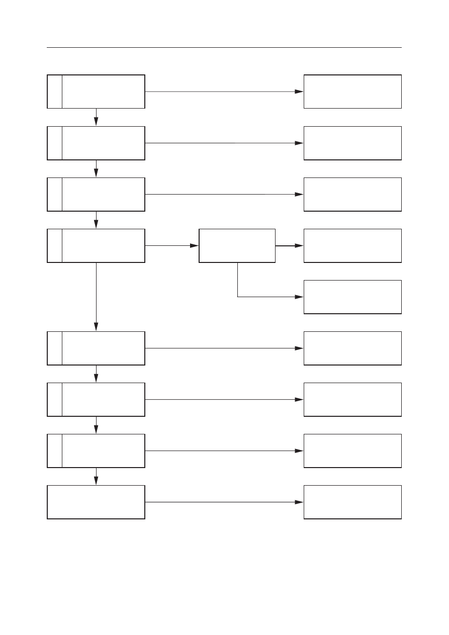
SLEWING SPEED IS LOW, OR THERE IS NO POWER.

1

3

4

Is the time needed for
slewing within the stan-
dard?

Within the standard.

Normal

Inspect the operation of
the spool.

Inspect the slew hydrau-
lic pressure.

Repair or replace the pilot
valve.

Repair or replace the housing
block.

Adjust the set pressure.

Not within the standard

2

Inspect the pilot valve.

Normal

Normal

Normal

Faulty

Faulty

Pressure is low.

Repair or replace the slew re-
lief valve.

7

Normal

Faulty

Repair or replace the slew re-
duction gear.

Adjust the pressure of
the slew relief valve.

Pressure does not rise.

6

5

Normal

Normal

Faulty

Faulty

Inspect the check valve
of the slew brake valve.

Inspect the slew motor
drainage amount.

Inspect the slew reduc-
tion gear.

The slew bearing is faulty.

Replace.

Repair or replace the slew
brake valve.

Repair or replace the slew
motor.

V-24

TROUBLESHOOTING

SLEWING

TB125, 135, 145

1. Is the time needed for slewing within the

standard?

“II. Specifications, Standards for Judging
Performance”

2. Inspect the pilot valve.

“V-19”

3. Inspect the operation of the spool.

“V-19”

4. Inspect the slew hydraulic pressure.

“V-19”

5. Inspect the check valve of the slew brake

valve.

“IV. Hydraulic Units, Slew Motor”

6. Inspect the slew motor drainage amount.

Operate the slew motor under the following con-
ditions and measure the amount of oil which
drains out in 1 minute.
a. Disconnect the drain hose (1) connected to the

motor and insert a plug (2) in the end of the
disconnected hose.

b. Install a hose (3)  for measuring the drainage

amount in the motor’s drain port.

c. Operate the motor for 1 minute and measure

the drainage amount. If it is as follows, the
drainage amount is normal.
Hydraulic Oil Temp.: 50~60

°

C

Engine Speed:

Rated Speed

Drainage Amount:

0.5 L/min or less

7. Inspect the slew reduction gear.

“IV. Hydraulic Units, Slew Motor”

V-25

TROUBLESHOOTING

SLEWING

TB125, 135, 145

THE MACHINE SLEWS, BUT OVERRUN WHEN SLEWING STOPS IS GREAT, OR IT CANNOT BE STOPPED.

1

2

4

Is the amount of overrun
when slewing stops
within the standard?

Within the standard.

Normal.

Inspect the pilot valve.

Inspect the slew hydrau-
lic pressure.

Repair or replace the pilot
valve.

Repair or replace the housing
block.

Adjust the set pressure.

Repair or replace the slew re-
lief valve.

Not within the standard.

Normal

Faulty

3

5

Inspect the operation of
the spool.

Inspect the slew brake
valve.

Normal

Normal

Faulty

Pressure is low.

Repair replace the slew brake
valve.

Adjust the pressure of
the slew relief valve.

Pressure doesn’t rise

1. Is the amount of overrun when slewing stops

within the standard?

“II. Specifications, Standards for Judging
Performance”

2. Inspect the pilot valve.

Inspect if the spool of the pilot valve returns to the
neutral position when the operation lever (slew)
is released after operation. Disconnect the hose
between the pilot valve and the control valve
(slew section) on the control valve side, then set
a pressure gauge in the disconnected hose.
• Read the pressure gauge after operating the

lever (slew), then releasing it.

• If the pressure is zero, the pilot valve is normal.

V-26

TROUBLESHOOTING

SLEWING

TB125, 135, 145

3. Inspect the operation of the spool.

 Inspect if the spool of the control valve (slew
section) returns to the neutral position when the
operation lever (slew) is released after operation.
Disconnect the line from the slew section of the
control valve, then set a pressure gauge in its
supply port.
• Read the pressure gauge after operating the

lever (slew), then releasing it.

• If the pressure is zero, the pilot valve is normal.

4. Inspect the slew hydraulic pressure.

“V-19”

5. Inspect the slew brake valve.

“IV. Hydraulic Units, Slew Motor”

V-27

TROUBLESHOOTING

SLEWING

TB125, 135, 145

1

2

3

Is the amount of natural
drop within the standard?

Within the standard.

Normal

Inspect the slew hydrau-
lic pressure.

Inspect the slew motor.

Adjust the set pressure.

Repair or replace the brake
valve.

Repair or replace the slew
motor.

Not within the standard.

Normal

Pressure is low.

Faulty

WHEN STOPPED ON A SLOPE, THE SLEWING BODY CANNOT MAINTAIN ITS POSTURE AFTER STOPPING.

Inspect the relief valve
pressure of the slew
brake valve.

Pressure does not rise.

1. Is the amount of natural drop within the

standard?

“II. Specifications, Standards for Judging
Performance”

2. Inspect the slew hydraulic pressure.

“V-19”

3. Inspect the slew motor.

“IV. Hydraulic Units, Slew Motor”

V-28

TROUBLESHOOTING

BOOM

TB125, 135, 145

1

3

4

Inspect the operation of
actuators other than the
boom cylinder.

Inspect the operation of
the spool.

Perform a port relief
valve switching test.

Repair or replace the pilot
valve.

Repair or replace the housing
block.

Repair or replace the port re-
lief valve.

Normal

2

5

Inspect the pilot valve.

Normal

Normal

Does not change.

Faulty

Faulty

Operation
became normal.

Repair or replace the boom
cylinder.

Inspect the boom cylin-
der.

Faulty

THE BOOM CYLINDER DOESN’T MOVE.

The port relief valve is
faulty.

1. Inspect the operation of actuators other than

the boom cylinder.

Inspect if the operation of the boom cylinder only
is faulty by the table at right. If its operation is
faulty, inspect the main relief valve and the hy-
draulic pump.

“V-6”

Right Travel

Relief Valve R1

Pump P1

Lever Operated

Places inspected

V-29

TROUBLESHOOTING

BOOM

TB125, 135, 145

2. Inspect the pilot valve.

Disconnect the hose between the pilot valve and
control valve (boom section) on the control valve
side, then set a pressure gauge in the disconnected
hose.
• Operate the (boom) lever and measure the

pressure.

• Depending the operation angle, if the pressure

is normal, it will range between 0~3.4 MPa
(0~35 kgf/cm

2

).

3. Inspect the operation of the spool.

Disconnect the hose between the control valve
(boom section) and the cylinder on the cylinder
side, then set a pressure gauge in the disconnected
hose.
• Operate the (boom) lever and measure the

pressure.

• A pressure of 20.6 MPa (210 kgf/cm

2

) is nor-

mal.

4. Perform a port relief valve switching test.

Switch the port relief valve for the port relief
valve of the normal arm. If the boom cylinder
operates, the boom side port relief valve is faulty.

V-30

TROUBLESHOOTING

BOOM

TB125, 135, 145

5. Inspect the boom cylinder.

a. Disconnect the hose between the control valve

and the boom cylinder on the control valve
side.

b. Connect the disconnected hose to the arm

section or the bucket section.

c. Try operating the boom cylinder. If the cylin-

der doesn’t operate, the cylinder is faulty.

When performing the operation in “a~c”
above, the bucket cylinder should be fully
extended, the arm cylinder should be fully
retracted and the bucket should be lowered
to the ground.

V-31

TROUBLESHOOTING

BOOM

TB125, 135, 145

BOOM CYLINDER OPERATION IS SLOW, OR THERE IS NO POWER.

1

3

4

Is the boom cylinder’s
speed within the stan-
dard?

Inspect the operation of
the spool.

Perform a port relief
valve switching test.

Normal

Repair or replace the housing
block.

Repair or replace the port re-
lief valve.

Not within the standard.

2

5

Inspect the pilot valve.

Normal

Normal

Does not change

Faulty

Faulty

Operation
became normal.

Repair or replace the boom
cylinder.

Inspect the boom cylin-
der.

Faulty

The port relief valve is
faulty.

Within the standard.

Repair or replace the pilot
valve.

1. Is the boom cylinder’s speed within the stan-

dard?

“II. Specifications, Standards for Judging
Performance”

2. Inspect the pilot valve.

“V-29”

3. Inspect the operation of the spool.

“V-29”

4. Perform a port relief valve switching test.

“V-29”

V-32

TROUBLESHOOTING

BOOM

TB125, 135, 145

5. Inspect the boom cylinder.

Boom Cylinder internal Leakage Inspect (1)
a. With the bucket cylinder fully retracted and

with the rod of the arm cylinder a little ex-
tended from the fully retracted position, lower
the bucket front end to the ground.

b. Disconnect the rod side hose (A) only and let

the oil in the piping run out.
Insert a plug (1) in the disconnected hose.

c. Retract the arm cylinder and lift the bucket so

it is floating above the ground.
At this time, if there is oil leaking from the
piping of the cylinder where the hose was
disconnected, and if the boom cylinder’s rod is
retracted, the cylinder is leaking internally.
Also, if there is no leakage of oil from the
cylinder’s piping, if the boom cylinder’s rod is
retracted, the control valve is leaking inter-
nally.

Boom Cylinder Internal Leakage Inspect (2)
a. Place the machine in the posture shown in the

figure.

SLIGHTLY EXTEND THE ROD

V-33

TROUBLESHOOTING

BOOM

TB125, 135, 145

b. Disconnect the head side hose (B) and let the

hydraulic oil out of the cylinder’s piping.
Insert a plug (2) in the disconnected hose.

c. Operate the bucket and raise the machine’s

body.
At this time, if there is oil leaking from the
piping of the cylinder where the hose was
disconnected, and if the boom cylinder’s rod is
extended, the cylinder is leaking internally.
Also, if there is no leakage of oil from the
cylinder’s piping, if the boom cylinder’s rod is
extended, the control valve is leaking inter-
nally.

If the cylinder is damaged internally, the
system should be flushed out to remove any
broken pieces (NAS Class 9).

V-34

TROUBLESHOOTING

BOOM

TB125, 135, 145

WHEN THE BOOM OPERATION LEVER IS PULLED GENTLY, THE BOOM DROPS TEMPORARILY.

1

2

Inspect the load check
valve of the control valve.

Faulty

Repair or replace the housing
block.

Inspect for internal leak-
age in the boom cylinder.

Repair or replace the boom
cylinder.

Normal

Faulty

1. Inspect the load check valve of the control

valve.

a. Disconnect the hose between the control valve

and boom cylinder at the control valve side.

b. Connect the disconnected hose to the arm or

bucket section.

c. Try operating the boom cylinder.
If operation is normal, the load check valve is
faulty.

Place the machine in the following posture
when performing the operation in “a~c” above.
• The bucket cylinder should be fully ex-

tended, the arm cylinder should be fully
retracted and the bucket should be low-
ered to the ground.

Reference: When the spool first starts to pull, the
oil’s pressure and flow are small, so if the load
check valve is faulty, it causes a load to bear on the
boom cylinder, which causes the oil to flow
backwards for a time. For this reason, the boom
will drop temporarily.

2. Inspect for internal leakage in the boom

cylinder.

When the boom cylinder’s piston or tube is faulty,
if oil is leaking from the head side (A) to the rod
side (B), since the oil’s pressure and flow are low
when the spool first starts pulling, the boom
cylinder will drop temporarily. Also, the cylinder
will have inadequate driving force. However, in
this case as well, the amount of natural drop will
be great.
• Cylinder Inspect

“V-32~33”

V-35

TROUBLESHOOTING

BOOM

TB125, 135, 145

2

3

Inspect for internal leak-
age in the boom cylinder.

Perform a port relief
valve switching test.

Repair or replace the boom
cylinder.

Repair or replace the port re-
lief valve.

1

Is the amount of natural
drop within the standard?

Not within the standard.

Normal

Normal

Within the standard.

Faulty

Faulty

The control valve is leaking
internally.

The port relief valve is
faulty.

Normal

THE AMOUNT OF BOOM NATURAL DROP IS GREAT.

Replace the housing block.

1. Is the amount of natural drop within the

standard?

“II. Specifications, Standards for Judging
Performance”

2. Inspect for internal leakage in the boom

cylinder.

“V-32~33”

3. Perform a port relief valve switching test.

“V-29”

V-36

TROUBLESHOOTING

ARM

TB125, 135, 145

THE ARM CYLINDER DOESN’T MOVE.

1

3

4

Inspect the operation of
actuators other than the
arm cylinder.

Inspect the operation of
the spool.

Perform a port relief
valve switching test.

Repair or replace the pilot
valve.

Repair or replace the housing
block.

Repair or replace the port re-
lief valve.

Normal

2

5

Inspect the pilot valve.

Normal

Normal

Does not change.

Faulty

Faulty

Operation
became normal.

Repair or replace the arm cyl-
inder.

Inspect the arm cylinder.

Faulty

The port relief valve is
faulty.

1. Inspect the operation of actuators other than

the arm cylinder.

Inspect if the operation of the arm only is faulty by
the table at right. If operation is faulty, inspect the
main relief valve and the hydraulic pump.

“V-6”

2. Inspect the pilot valve.

“V-29”

Left Travel

Relief Valve R2

Pump P2

Lever Operated

Places inspected

V-37

TROUBLESHOOTING

ARM

TB125, 135, 145

3. Inspect the operation of the spool.

Disconnect the arm hose connected to the pipe at
the boom foot, then set a pressure gauge in the
disconnected hose.
• Operate the (arm) lever and measure the pres-

sure.

• If the pressure is 20.6 MPa (210 kgf/cm

2

), it is

normal.

4. Perform a port relief valve switching test.

Switch the port relief valve with that of the
normal boom. If the arm cylinder then operates,
the port relief valve is faulty.

5. Inspect the arm cylinder.

Switch the arm hoses and bucket hoses connected
to the pipes at the boom foot.
• Try operating the (bucket) operation lever to

operate the arm cylinder.

• If the cylinder doesn’t operate, the cylinder is

faulty.

When performing the operation above, the
bucket cylinder should be fully extended, the
arm cylinder should be fully retracted, and
the bucket should be lowered to the ground.

ARM

BUCKET BUCKET

ARM

ARM BUCKET BUCKET ARM

V-38

TROUBLESHOOTING

ARM

TB125, 135, 145

ARM CYLINDER OPERATION IS SLOW, OR THERE IS NO POWER.

1

3

4

Is the arm cylinder’s
speed within the stan-
dard?

Inspect the operation of
the spool.

Perform a port relief
valve switching test.

Normal

Repair or replace the housing
block.

Repair or replace the port re-
lief valve.

Not within the standard.

2

5

Inspect the pilot valve.

Normal

Normal

Does not change

Faulty

Faulty

Operation
became normal.

Repair or replace the arm cyl-
inder.

Inspect the arm cylinder.

Faulty

The port relief valve is
faulty.

Within the standard.

Repair or replace the pilot
valve.

1. Is the arm cylinder’s speed within the stan-

dard?

“II. Specifications, Standards for Judging
Performance”

2. Inspect the pilot valve.

“V-29”

3. Inspect the operation of the spool.

“V-37”

4. Perform a port relief valve switching test.

“V-37”


Content      ..     37      38      39      40     ..