Takeuchi compact excavator TB125, TB135, TB145 / diesel TNE / diesel Yanmar. Service Manual - page 38
 

  Index      Manuals     Takeuchi compact excavator TB125 (12510003~), TB135 (13510004~), TB145 (14510004~) / diesel TNE / diesel Yanmar. Service Manual


Search            copyright infringement  


Content      ..     36      37      38      39     ..


Takeuchi compact excavator TB125, TB135, TB145 / diesel TNE / diesel Yanmar. Service Manual - page 38


V-7

TROUBLESHOOTINTG

OVERALL MACHINE

TB125, 135, 145

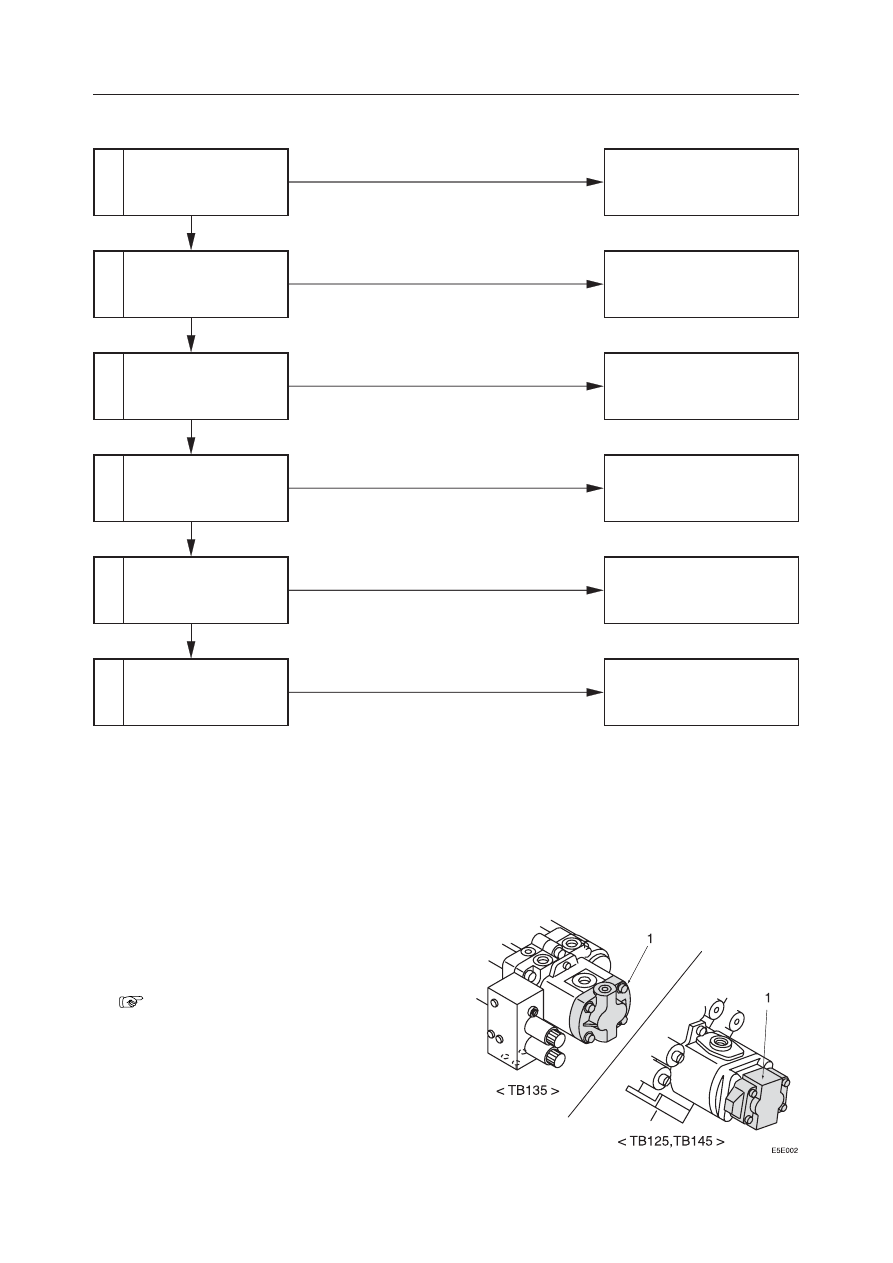
THE BOOM, BUCKET, SLEW AND ARM DO NOT MOVE AT ALL, OR THE SPEED IS LOW.

1

2

3

4

5

6

Inspect the hydraulic
pump P4.

Inspect the fuse.

Inspect the limit switch.

Inspect the lever lock so-
lenoid valve.

Inspect the pilot relief
valve.

Inspect the pilot valve.

Normal

Normal

Normal

Normal

Normal

Faulty

Faulty

Faulty

Faulty

Faulty

Faulty

Repair or replace the hydrau-
lic pump P4.

Replace the fuse.

Adjust or replace the limit
switch.

Repair or replace the lever lock
solenoid valve.

Adjust, repair or replace the
pilot relief valve.

Repair or replace the pilot
valve.

1. Inspect the hydraulic pump P4.

Inspect the hydraulic pump P4 (1) which is the
source of the hydraulic pressure for the pilot
valve.

“V-4”

Since clogging of the line filter can also be con-
sidered, inspect and clean the filter.

V-8

TROUBLESHOOTINTG

OVERALL MACHINE

TB125, 135, 145

2. Inspect the fuse.

Inspect the fuse for the electric power circuit that
operates the pilot solenoid valve.

3. Inspect the limit switch.

Set the lever stand to the operation position to turn
on the limit switch. Check the voltage at the lever
lock solenoid valve by using a tester.
• The limit switch is normal if the voltage is

being applied.

Reference: If the limit switch is found to be faulty
and the attachment must be moved, connect the
lever lock release connectors A and B for emer-
gency use. These connectors are taped on the
main harness under the engine muffler.

“III-113”

4. Inspect the lever lock solenoid valve.

Inspect by the following procedure.
a. Turn the starter switch to the “ON” position.
b. Push lightly on the projection on the front end

of the solenoid valve.

c. Move the lever stand and change the limit

switch from “OFF” to “ON”.

d. If the spool moves and vibration can be felt

with the fingertip when the circuit changes,
then it is normal.

5. Inspect the pilot relief valve.

Measure the relief pressure of the pilot relief
valve.
• If the pressure is the standard value, the valve

is normal.

“II. Specifications, Standards for Judging
Performance”

6. Inspect the pilot valve.

“IV. Hydraulic Units, Pilot Valve”

V-9

TROUBLESHOOTINTG

MACHINE TRAVEL

TB125, 135, 145

1

2

3

THE MACHINE WILL NOT TRAVEL AT ALL.

Inspect the pressure sup-
plied to the travel lever
lock cylinder.

Inspect the linkage.

Inspect the travel lever
lock cylinder.

Normal

Normal

Faulty

Faulty

Adjust, repair or replace the
linkage.

Replace the travel lever lock
cylinder.

1. Inspect the pressure supplied to the travel

lever lock cylinder.

Disconnect the hose between the solenoid valve
and the travel lever lock cylinder on the cylinder
side. Connect a pressure gauge to the discon-
nected hose and measure the pilot pressure.
• Keep the plug assembled on the port of the

disconnected cylinder.

•  Standard value: Approx. 3.4 MPa (35 kgf/cm

2

)

2. Inspect the linkage.

Inspect the operating status of the travel lever
lock cylinder (1) and slide plate (2).
• The cylinder stroke should be 10 mm.
• Inspect the operating status of the lever lock

cylinder and slide plate. Also, check whether
the fixing bolt or nut is loose.

3. Inspect the travel lever lock cylinder.

The travel lever lock cylinder cannot be disas-
sembled. If it is faulty, replace it.

V-10

TROUBLESHOOTINTG

MACHINE TRAVEL

TB125, 135, 145

1

2

3

4

5

6

RIGHT OR LEFT TRAVEL IS IMPOSSIBLE.

Inspect the operation of
actuators other than the
travel motor.

Inspect spool operation.

Inspect the linkage.

Inspect the swivel joint.

Inspect the counterbal-
ance valve.

Inspect the travel motor.

Normal

Normal

Normal

Normal

Normal

Faulty

Faulty

Faulty

Faulty

Faulty

Repair or replace the housing
block.

Adjust, repair or replace the
parts.

Repair or replace the swivel
joint.

Repair or replace the counter-
balance valve.

Repair or replace the travel
motor.

1. Inspect the operation of actuators other than

the travel motor.

If operation of the right or left travel motor is
impossible, operate each respective actuator in
accordance with the table at right. If operation is
faulty, inspect the main  relief valve and pump.

2. Inspect spool operation.

• Spool Stroke : 6.0 mm
• If the spool is sticking, take it out and inspect

it. If it can’t be taken out, or if it is scratched,
replace the housing block.
Another cause of the spool not operating prop-
erly could be that the return spring installation
bolt is loose.

Lever

Operated

Place Inspected

If right travel
is impossible
If left travel is
impossible

Boom

Arm

Main Relief
valve R1
Main Relief
valve R2

Pump P1

Pump P2

V-11

TROUBLESHOOTINTG

MACHINE TRAVEL

TB125, 135, 145

3. Inspect the linkage.

The inspection of the linkage is done by inspect-
ing the movement of the yoke (1) without the R
pin (2) and the pin (3) which connect the yoke (1)
and the spool.

4. Inspect the swivel joint.

• Disconnect the hose between the swivel joint

and the counterbalance valve from the coun-
terbalance valve side and set a pressure gauge
in the hose.

• Operate the travel lever and measure the pres-

sure.

• The swivel joint is normal if the pressure gauge

reading indicates the standard value.
Standard value:

Approx. 20.6 MPa (210 kgf/cm

2

)

5. Inspect the counterbalance valve.

• If neither forward nor reverse travel is pos-

sible, the spool (1) of the counterbalance valve
could be sticking in the neutral position.

• If either forward or reverse travel is possible,

the spool (1) of the counterbalance valve could
be sticking in a position other than the neutral
position.

• Disconnect the counterbalance valve plug (2)

and try pushing the spool (1) with a finger. It is
normal if it moves smoothly about 6 mm.

6. Inspect the travel motor.

“IV. Hydraulic Units, Travel Motor”

V-12

TROUBLESHOOTINTG

MACHINE TRAVEL

TB125, 135, 145

SPEED DROPS IN THE LEFT OR RIGHT TRAVEL, CAUSING THE MACHINE TO TRAVEL IN A CURVE.

1

2

3

4

5

6

7

8

Is the amount of travel
curve within standard?

Inspect the crawler ten-
sion and inspect for for-
eign matter biting in, etc.

Inspect the operation of
the spool.

Switch the left and right
pump discharge hoses.

Switch the left and right
main relief valves and
test.

Inspect the swivel joint.

Inspect the counterbal-
ance valve.

The travel motor’s speed
reducer unit is faulty.

Not within Standard

Not abnormal

Normal

No change

No change

Normal

Normal

Within
standard

Faulty

Faulty

The direction of travel curve
changes to the opposite side.

The direction of travel
curve changes to the
opposite side.

Faulty

Faulty

Depends on the com-
bination of equipment.

Inspect the main relief
valve.

Normal

Adjust to the proper dimen-
sions or remove the foreign
matter.

Repair or replace the housing
block.

• Repair the pump or replace it.
• Replace the hydraulic oil

and filter.

Repair or replace the main
relief valve.

Repair or replace the swivel
joint.

Repair or replace the counter-
balance valve.

Repair or replace the travel
motor.

V-13

TROUBLESHOOTINTG

MACHINE TRAVEL

TB125, 135, 145

1. Is the amount of travel curve within stan-

dard?

If the amount of travel curve is within standards,
then operation is normal and the variation de-
pends on the combination of equipment.

“II. Specifications, Standards for Judging
Performance”

2. Adjust the tension of the crawler belt.

“II. Specifications, Standards for Judging
Performance”

3. Inspect the operation of the spool.

“V-10”

4. Switch the left and right pump discharge

hoses.

Switch the discharge hoses for Pump P1 and
Pump P2. The pump is faulty if the direction in
which the machine curves during travel is in the
opposite direction.
• Disassemble and inspect the pump.

“IV. Hydraulic Units, Hydraulic Pump”

5. Switch the left and right main relief valves

and test.

Switch the left and right main relief valves and
test. If the direction in which the machine curves
during travel changes to the opposite direction,
the main relief valve is faulty.
• Inspect the main relief valve

“V-6”

V-14

TROUBLESHOOTINTG

MACHINE TRAVEL

TB125, 135, 145

6. Inspect the swivel joint.

“V-11”

7. Inspect the counterbalance valve.

Inspect if the counterbalance valve’s plunger
moves smoothly.

“V-11”

8. The travel motor’s speed reducer unit is

faulty.

“IV. Hydraulic Units, Hydraulic Pump”

V-15

TROUBLESHOOTINTG

MACHINE TRAVEL

TB125, 135, 145

1

2

3

4

5

6

7

8

MACHINE WON’T ACCELERATE DURING TRAVEL.

Inspect the hydraulic
pump P4.

Inspect the pilot relief
valve.

Inspect the fuse.

Inspect the travel speed
switch.

Inspect the 2nd speed re-
lay.

Inspect the 2nd speed
solenoid valve.

Inspect the swivel joint.

The 2nd speed control
valve is faulty.

Normal

Normal

Normal

Normal

Normal

Normal

Normal

Faulty

Faulty

Faulty

Faulty

Faulty

Faulty

Faulty

Faulty

Repair or replace the hydrau-
lic pump P4.

Adjust, repair or replace the
pilot relief valve.

Replace the fuse.

Replace the travel speed
switch.

Replace the 2nd speed relay.

Repair or replace the 2nd
speed solenoid valve.

Repair or replace the swivel
joint.

Repair or replace the 2nd
speed control valve.

1. Inspect the hydraulic pump P4.

Inspect the hydraulic pump P4 which is the
source of the hydraulic pressure for switching to
second gear.

“V-6”

Since clogging of the line filter can also be
considered, inspect and clean the filter.

V-16

TROUBLESHOOTINTG

MACHINE TRAVEL

TB125, 135, 145

2. Inspect the pilot relief valve.

Measure the relief pressure of the pilot relief
valve.
• If the pressure is the standard value, the valve

is normal.

“II. Specifications, Standards for Judging
Performance”

3. Inspect the fuse.

Operate the 2nd speed solenoid valve and check
the fuse for the power supply circuit.

4. Inspect the travel speed switch.

Press the switch to turn it “ON”. While it is in this
condition, check if there is continuity with a
tester.

5. Inspect the 2nd speed relay.

Press the travel speed switch to turn the second
speed relay to “ON.”  Check whether the voltage
is applied to the second speed solenoid valve by
using a tester. Be sure to stop the engine before
starting the inspection.

V-17

TROUBLESHOOTINTG

MACHINE TRAVEL

TB125, 135, 145

6. Inspect the 2nd speed solenoid valve.

a. Turn the start switch “ON”.
b. Press the protruding portion of the solenoid

valve lightly.

c. Turn the travel speed switch “ON”.
d. If the spool moves and vibration can be felt

with the fingertip when the circuit changes,
then it is normal.

7. Inspect the swivel joint.

Disconnect the hose between the swivel joint and
the 2nd speed control valve at the 2nd speed
control valve side. Set a pressure gauge in the
disconnected end of the hose and turn on the 2nd
speed switch.
• A pressure of 3.4 MPa (35 kgf/cm

2

) is normal.

8. The 2nd speed control valve is faulty.

Check if the plunger of the 2nd speed control
valve is sticking or if foreign matter is caught in
it.

“IV. Hydraulic Units, Travel Motor”

C4E013

V-18

TROUBLESHOOTINTG

SLEWING

TB125, 135, 145

1

2

3

4

5

6

NO SLEWING CAN BE DONE.

Inspect the operation of
actuators other than the
slew motor.

Inspect the pilot valve.

Inspect the operation of
the spool.

Inspect the slew hydrau-
lic pressure.

Inspect the slew motor.

Inspect the slew reduc-
tion gear.

The slew bearing is faulty.

Normal

Normal

Normal

Normal

Normal

Normal

Adjust the slew relief
valve pressure.

Pressure does not rise

Faulty

Faulty

Pressure is low.

Faulty

Faulty

Repair or replace the pilot
valve.

Repair or replace the housing
block.

Adjust the set pressure.

Repair or replace the slew re-
lief valve.

Repair or replace the slew
motor.

Repair or replace the slew re-
duction gear.

Replace.

1. Inspect the operation of actuators other than

the slew motor.

Inspect if the operation of the slew motor only is
faulty by the table at right. If its operation is
faulty, inspect the main relief valve and the hy-
draulic pump.

“V-6”

Lever Operated

Places inspected

Dozer Blade

Relief Valve R3

Pump P3

V-19

TROUBLESHOOTINTG

SLEWING

TB125, 135, 145

2. Inspect the pilot valve.

Disconnect the hose between the pilot valve and
control valve (slew section) at the control valve
side, then set a pressure gauge in the disconnected
hose.
• A plug should be inserted in the control valve

port.

• Operate the lever (slew) and measure the pres-

sure.

• Depending on the operating angle, a pressure

in the 0~3.4 MPa (0~35 kgf/cm

2

) range is

normal.

3. Inspect the operation of the spool.

Disconnect the hose that goes between the control
valve (slew section) and the slew motor at the
valve side and set a pressure gauge to the dis-
charge port of the valve.
• Operate the lever (slew) and measure the pres-

sure.

• The operation of the spool is normal if it agrees

with the following value of supply pressure:

19.6 MPa (200 kgf/cm

2

)

4. Inspect the slew hydraulic pressure.

Measure the pressure at the left and right slew
relief valves.
• The pressure is normal if it is the standard

value.

“II. Specifications, Standards for Judging
Performance”

 If adjustment of the pressure is possible, the slew
relief valve’s adjustment is faulty. Also, if the
pressure adjustment is impossible, the slew relief
valve is faulty.

5. Inspect the slew motor.

Separate the slew motor and reduction gear (1)
and turn the motor (2) only.
• If it turns, the reduction gear or the slew bear-

ing (3) is faulty.

• If it doesn’t turn, the slew motor is faulty.

V-20

TROUBLESHOOTINTG

SLEWING

TB125, 135, 145

6. Inspect the slew reduction gear.

Separate the reduction gear from the turntable (4)
and turn the pinion manually.
• If it turns, the slew bearing is faulty.
• If it doesn’t turn, the reduction gear is faulty.

V-21

TROUBLESHOOTINTG

SLEWING

TB125, 135, 145

1

2

3

4

5

RIGHT OR LEFT SLEWING CANNOT BE DONE.

Inspect the pilot valve.

Inspect the operation of
the spool.

Inspect the slew relief
valve.

Inspect the check valve
of the slew brake valve.

The slew motor is faulty.

Normal

Normal

Normal

Normal

Faulty

Faulty

Faulty

Faulty

Repair or replace the pilot
valve.

Repair or replace the housing
block.

Repair or replace the slew re-
lief valve.

Repair or replace the slew
brake valve.

Repair or replace the slew
motor.

1. Inspect the pilot valve.

It could be that the spool for only the side of the
pilot valve for which slewing is impossible will
not operate.

“V-19”

2. Inspect the operation of the spool.

It could be that the spool will not move only in the
direction in which slewing is impossible.

“V-19”

V-22

TROUBLESHOOTINTG

SLEWING

TB125, 135, 145

3. Inspect the slew relief valve.

Try switching the left and right slew relief valves.
If slewing becomes possible, the relief valve is
faulty.

4. Inspect the check valve of the slew brake

valve.

If foreign matter is caught in one end of the check
valve (1), or if the valve is sticking, right or left
slewing will be impossible.
• If foreign matter is caught in one of the check

valves, the hydraulic oil returns to the tank
from the check valve.

5. The slew motor is faulty.

“IV. Hydraulic Units, Sew Motor”


Content      ..     36      37      38      39     ..