Takeuchi compact excavator TB125, TB135, TB145 / diesel TNE / diesel Yanmar. Service Manual - page 37
 

  Index      Manuals     Takeuchi compact excavator TB125 (12510003~), TB135 (13510004~), TB145 (14510004~) / diesel TNE / diesel Yanmar. Service Manual


Search            copyright infringement  


Content      ..     35      36      37      38     ..


Takeuchi compact excavator TB125, TB135, TB145 / diesel TNE / diesel Yanmar. Service Manual - page 37


IV-260

HYDRAULIC UNITS

SLEW MOTOR

TB125, 135, 145

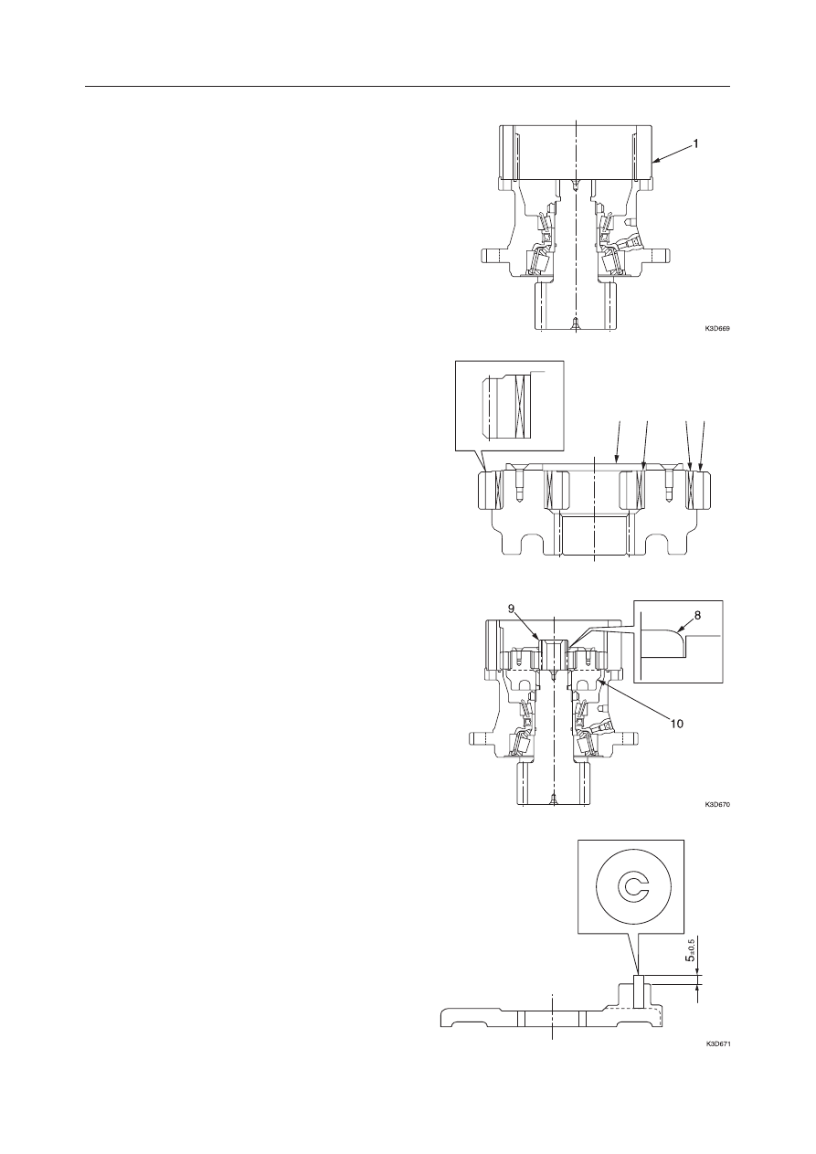
10. Fit the O-ring to the case and mount the ring gear

(1).
• Align the positions of the M12 hole of the case

and the hole (ø13 mm in diameter) of the ring
gear.

11. Mount the inner race (14), needles (13) and plan-

etary gear B (12) on the carrier 2.
• Be careful of the mounting direction of the

planetary gear B.

12. Mount the thrust plate (11) and fix it with the cap

screws.
• Apply Loctite #242 to the cap screws in ad-

vance.

• Cap screw tightening torque:

6.1 

±

2.0 N·m (0.6 

±

0.2 kgf·m)

13. Mount the carrier 2 (10) on the case.

14. Fit the snap ring (8) to the sun gear (9) and mount

them.

15. Fit the spring pin to the carrier 1.

• Let the slit section of the spring face outside as

shown in the figure.

K3D651

11

14

13 12

IV-261

HYDRAULIC UNITS

SLEW MOTOR

TB125, 135, 145

16. Mount the carrier 1 (7).

17. Mount the inner race (5), needles (6) and plan-

etary gear A (4) on the carrier 1 (7).
• Mount the planetary gear A as shown in the

figure.

18. Mount the drive gear (3).

19. Mount the thrust plate (2).

• Measure the depth (A) from the case end to the

carrier 1 and select a proper thickness for the
thrust plate by referring to the table.

• The largely-rounded side of the thrust plate

circumference should face the planetary gear.

Slew Motor

1. Unite the hydraulic motor (1) and the reduction

gear (2) and fix them with the cap screws.
• Cap screw tightening torque:

128 

±

7 N·m (13.1 

±

0.7 kgf·m)

Depth (A)

Less than 14.0 mm

From 14.0 to less

than 14.5 mm

14.5 mm or more

Thrust plate

thickness

1.8 mm

2.3 mm

2.8 mm

K3D627

2

1

IV-262

HYDRAULIC UNITS

SLEW MOTOR

TB125, 135, 145

INSPECTION AND ADJUSTMENT

“IV-235”

TROUBLESHOOTING

“IV-236”

2. Fit the O-ring to the cover.

3. Fit the anti-rebound valve to the cover and mount

the washer, seal and screws.
• Screw tightening torque:

29.4 

±

2 N·m (3.0 

±

0.2 kgf·m)

K3D626

IV-263

HYDRAULIC UNITS

SWIVEL JOINT

TB125, 135, 145

SWIVEL JOINT

CONSTRUCTION

TB125

  1. Shaft
  2. Hub
  3. Flange
  4. Thrust Ring
  5. Pin
  6. Slipper Seal
  7. O-ring
  8. O-ring
  9. Backup Ring
10. Dust Seal
11. Snap Ring
12. Plug
13. Plug

  1. Shaft
  2. Hub
  3. Flange
  4. Thrust Ring
  5. Pin
  6. Slipper Seal
  7. O-ring
  8. O-ring
  9. Backup Ring
10. Dust Seal
11. Snap Ring
12. Dust Seal

TB135, TB145

E5D700

12

5

10

9

7

6

4

11

8

3

2

1

13

G4D700

5

4

11

3

8

2

6

7

9

12

1

10

13

IV-264

HYDRAULIC UNITS

SWIVEL JOINT

TB125, 135, 145

OPERATION

The swivel joint is mounted in the center of the
machine’s slew axis. It serves the role of maintaining
continuous connections in the hydraulic circuit re-
gardless of the upper frame’s slew angle.
Above the hub (1) and shaft (2), which are capable of
rotating together, ports (3) are included for oil for the
necessary number of circuits only. The inner circum-
ference surface of the hub and the outer circumfer-
ence surface of the shaft, grooves are cut which serve
as passages for hydraulic oil. Seals (4) are placed
above and below these circumferential grooves.
Oil flowing in from a port flows constantly through
this hydraulic passage (5) between the hub and shaft
and the circuits can be connected without a break
when the upper frame is slewing.

IV-265

HYDRAULIC UNITS

SWIVEL JOINT

TB125, 135, 145

DISASSEMBLY AND ASSEMBLY

General Cautions

• Carry out disassembly and assembly in a clean

work area and provide clean containers to hold the
disassembled parts.

• Clean thoroughly around the ports and remove the

paint on the joints of each part with a wire brush.

• Clean the disassembled parts with a cleaning fluid

such as diesel fuel.

• Replace the seals with new ones each time the

swivel joint is disassembled, applying a thin coat-
ing of grease to them.

• Check each part for abnormal wear or seizing. Also

remove any burrs or sharp edges, etc. with sandpa-
per or by a similar method.

• Check for foreign matter or dirt, etc. in the seal

grooves.

The following describes the disassembly procedure.
For assembly, follow the disassembly procedure in
the reverse order.

Disassembly

1. Take out the bolts and remove the spring washers,

then remove the flange (1) from the hub.
• Tightening torque:

27.5 N·m (2.8 kgf·m) .................... TB125
24.5~39.2 N·m (2.5~4.0 kgf·m) .... TB135,TB145

• During assembly, place a pipe on the stopper

pin of the shaft and check if the shaft rotates.

2. Remove the O-ring (2), snap ring (3) and thrust

ring (4).
• During assembly, make sure the snap ring fist

securely in the groove.

3. Remove the shaft (5) from the hub.

• Place a knock pin (6) against the shaft end and

tap with a hammer. Select a knock pin (6) made
of copper or plastic, etc.

• Apply a thin coating of hydraulic oil or grease

to the outer circumference of the shaft.

IV-266

HYDRAULIC UNITS

SWIVEL JOINT

TB125, 135, 145

4. Remove the dust seal from the shaft.

5. Remove the seals from the inside diameter of the

hub.
• Check the positions of the seals in the struc-

tural drawing.

• Use an O-ring tooth or eyeleteer with a sharp

point on the end, etc.

• Do not deform or bend the slipper seal strongly

in any one place.

• During assembly, O-rings should not be twisted

when they are fitted in place.

IV-267

HYDRAULIC UNITS

SWIVEL JOINT

TB125, 135, 145

INSPECTION AND ADJUSTMENT

Inspection Procedure and Treatment

Inspection Interval

Place Inspected

Inspection Procedure

Treatment

2,000  hrs.

Seals which prevent ex-
ternal leakage of hy-
draulic oil

Check if oil is leaking out

Replace the O-rings if there
is leakage

4,000 hrs.
Disassemble and check
whether there is leak-
age or not

All seal parts

Check for abnormal wear,
scratches, corrosion, etc., due
to seizing, biting of foreign mat-
ter, etc.

Replace all seal parts
Treat in accordance with the
use limit

Treat in accordance with the
use limit. However, replace
the seal kit

Check for abnormal wear,
scratches, corrosion, etc., due
to seizing, biting of foreign mat-
ter, etc.

All sliding parts

All parts

When disassembling
due to breakdown

Checking the Parts

Hub, Shaft

Parts

Judgment Standard

Treatment

Seal parts and sliding
parts

• Parts which wear away due to wearing of surfaces

which have undergone ultrasonic tempering, and
parts which come off due to seizing, biting in of
foreign matter, etc.

Replace with new parts

• Parts with abnormal wear or with scratches 0.1 mm

deep or deeper due to seizing or biting in of foreign
matter, etc.

• Parts with scratches less than 0.1 mm deep
• Parts which are worn 0.5 mm or more, or abnormally

worn parts

• Parts with less than 0.5 mm of wear
• Parts with scratches due to seizing, biting in or

foreign matter, etc., which are within the wear limit
of 0.5 mm and which can be repaired

Hub and shaft sliding
parts other than seals

Portions which slide
against the thrust ring

Replace with new parts

Repair with an oil stone
Replace with new parts

Repair so that it is smooth

Flange

Parts

Judgment Standard

Treatment

Portions which slide
against the shaft end

• Parts which are worn 0.5 mm or more, or abnormally

worn parts

Replace with new parts

• Parts with less than 0.5 mm of wear
• Parts with scratches due to seizing, biting in or

foreign matter, etc., which are within the wear limit
of 0.5 mm and which can be repaired

Repair so that it is smooth

IV-268

HYDRAULIC UNITS

SWIVEL JOINT

TB125, 135, 145

Thrust Ring

Inspection after Assembly

After assembly is completed, carry out a leak check of
each circuit using the apparatus shown in the figure.

1. Connect a pipe (3) from the hydraulic pump (2) to

the shaft (1) side port.

2. Connect a pressure gauge (5) to the hub (4) side.
3. Increase the pressure gradually to 20.6 MPa while

adjusting the relief valve (6), then perform a 1
minute leak test.
• Release the neighboring ports on both sides

and check visually for leakage from the ports.

• Check for external leakage, etc., by a color

check.

Replace with new parts

Judgment Standard

• Parts which are worn 0.5 mm or more, or abnormally worn parts

Treatment

• Parts with less than 0.5 mm of wear
• Parts with scratches due to seizing, biting in or foreign matter, etc., which are

within the wear limit of 0.5 mm and which can be repaired

Repair so that it is smooth

IV-269

HYDRAULIC UNITS

SWIVEL JOINT

TB125, 135, 145

TROUBLESHOOTING

Symptom

Probable Causes

Remedy

External oil leakage

• O-ring is defective

• Replace all the seal parts

• Thrust ring is defective
• Great wear on sliding surfaces
• Shaft and hub are stuck together

• Replace all the seal parts
• Replace the assembly
• Carry out polishing and honing. If looseness

and oil leakage are great, replace the assem-
bly

• Socket bolt tightening is insuffi-

cient

• Retighten to the specified torque

Internal oil leakage

Shaft sticks

Flange looseness

IV-271

TB125, 135, 145

V .

  TROUBLESHOOTING

V-1

TB125, 135, 145

IV-272

TROUBLESHOOTING

TB125, 135, 145

CAUTIONS IN TROUBLESHOOTING AND REPAIRS

(1) Do not begin disassembling the equipment immediately just because it has broken down.

Conduct a thorough preliminary check before attempting disassembly.
a. Ask the user the following questions.

• What were the conditions when the machine broke down?
• Did anything abnormal happen before breakdown occurred?
• Are there any other places which were functioning poorly other than the part that broke

down?

• Are there any parts which have been repaired previous to the breakdown? What were

they?

• Has the same thing happened before?

b. Run the machine yourself and confirm the breakdown conditions.

• Judge whether the machine is really broken down or not following the judgment

standards.
The judgment on whether the machine has broken down may differ between individu-
als.

IMPORTANT:    When running the machine, it is possible that  moving the machine could
make the breakdown worse than it already is, so do not forget to ask the user if there is
anything to prevent your operating the machine.

c. Based on the information that you have gathered from the user and the information

obtained from running the machine yourself, judge the cause of the trouble. Also keep in
mind that it is difficult to reproduce the conditions of the breakdown again once the
machine has been disassembled, and early disassembly may make it impossible to
determine the true cause of the trouble. Therefore be sure to find the true cause of the
trouble before attempting disassembly.

(2) When it is thought that the trouble has more than one cause, begin investigating from the

simplest cause.

(3) Think over why the trouble could have occurred and try to correct the root cause of that

problem.

V-2

TB125, 135, 145

V-3

TROUBLESHOOTINTG

TB125, 135, 145

CONTENTS

OVERALL MACHINE

No operations can be done. ................................................................................................................................... 4

All operations can be done, but there is no power. ............................................................................................... 5

The boom, bucket, slew and arm do not move at all, or the speed is low. ............................................................ 7

MACHINE TRAVEL

The machine will not travel at all. ......................................................................................................................... 9

Right or left travel is impossible. ........................................................................................................................ 10

Speed drops in the left or right travel, causing the machine to travel in a curve. ............................................... 12

Machine won’t accelerate during travel. ............................................................................................................. 15

SLEWING

No slewing can be done. ...................................................................................................................................... 18

Right or left slewing cannot be done. .................................................................................................................. 21

Slewing speed is low, or there is no power. ........................................................................................................ 23

The machine slews, but overrun when slewing stops is great, or it cannot be stopped. ..................................... 25

When stopped on a slope, the slewing body cannot maintain its posture after stopping. ................................... 27

BOOM

The boom cylinder doesn’t move. ....................................................................................................................... 28

Boom cylinder operation is slow, or there is no power. ...................................................................................... 31

When the boom operation lever is pulled gently, the boom drops temporarily. ................................................. 34

The amount of boom natural drop is great. ......................................................................................................... 35

ARM

The arm cylinder doesn’t move. .......................................................................................................................... 36

Arm cylinder operation is slow, or there is no power. ........................................................................................ 38

The amount of arm natural drop is great. ............................................................................................................ 40

BUCKET

The bucket cylinder doesn’t move, or there is no power. ................................................................................... 41

The amount of bucket natural drop is great. ........................................................................................................ 43

BOOM SWING

The swing cylinder doesn’t move. ....................................................................................................................... 44

DOZER BLADE

The dozer blade cylinder doesn’t move, or there is no power. ............................................................................ 45

The amount of dozer blade natural drop is great or the dozer blade won’t hold the machine up. ...................... 47

AUXILIARY HYDRAULICS

The proportional control is impossible (TB145). ................................................................................................ 49

The flow in the auxiliary hydraulic circuit cannot be controlled (TB145). ......................................................... 51

V-4

TROUBLESHOOTINTG

OVERALL MACHINE

TB125, 135, 145

1

3

2

NO OPERATIONS CAN BE DONE.

Inspect the hydraulic oil
level

Pump or coupling is
faulty.

Insufficient

Proper Amount

Replenish the hydraulic
oil.

• Repair the pump or replace

the pump.

• Replace the coupling.

1. Inspect the hydraulic oil level.

“III. Machine Configuration, Hydraulic
Tank”

2. Replenish the hydraulic oil.

Take out the plug and replenish the hydraulic oil.
• The hydraulic oil supplied should be the same

brand as the oil currently in the tank.
“II. Specifications, Fluid Capacities”

• After replenishing the hydraulic oil, be sure to

pressurize the Hydraulic Tank.

“I-12”

3. Pump or coupling is faulty.

a. Disconnect the discharge hose (1) from the

pump side.
Also fit a plug in the disconnected hose to keep
the hydraulic oil from pouring out.

b. Disconnect the electrical wiring (2) to the

engine stop solenoid.

c. Turn the engine over using the starting motor

and inspect if hydraulic oil is discharged by the
pump.
• The throttle lever should be in the engine

stop position.

If the pump is normal, hydraulic oil will be
discharged from it. If hydraulic oil is not dis-
charged, the pump or the coupling is faulty.

C4E001

1

C4E002

2

V-5

TROUBLESHOOTINTG

OVERALL MACHINE

TB125, 135, 145

1

3

2

4

5

ALL OPERATIONS CAN BE DONE, BUT THERE IS NO POWER.

Inspect the hydraulic oil
level.

Noise generated by the
pump.

Inspect the main relief
valve.

Pump is faulty.

Proper Amount

No Noise

Normal

Insufficient

Noise

Faulty

Suction line is faulty.

Bubbles from inside
the tank.

Replenish the hydraulic
oil.

Replace the seal tape, O-rings,
hose.

Treat beginning at the source
of the bubbling.

Repair or replace the main
relief valve.

• Repair or replace the pump.
• Flush with hydraulic oil.

1. Inspect the hydraulic oil level.

“III. Machine Configuration, Hydraulic
Tank”

2. Replenish the hydraulic oil.

“V-4”

3. Noise generated by the pump.

A faulty suction line can make it easy for cavita-
tion to occur in the pump and for noise to be
generated. Carry out the following inspect.
a. Inspect the piping used for suction of hydraulic

oil.
• Apply grease or oil to the part which appears

to be making the noise and inspect if there is
any change. (Inspect if it is sucking in air or
not.)

b. Inspect for clogging of the suction filter.
c. Pressurize the Hydraulic Tank.

“I-12”

V-6

TROUBLESHOOTINTG

OVERALL MACHINE

TB125, 135, 145

4. Inspect the main relief valve.

Measure the relief pressure of the main relief
valve.
• The valve is normal if the pressure gauge

reading is the standard value.

“ II. Specifications, Standards for Judging
Performance”

If the main relief valve’s set pressure is too low,
adjust it by tightening the valve set screw gradu-
ally.
• If the pressure doesn’t rise after 1/4 turn of the

screw, the main relief valve is faulty.

Cautions During Disassembly and Assembly

• The dimension A of the set screw (1) should be

measured and recorded when the cap nut (2) is
removed.

• Inspect for biting of foreign matter and for scratches

in the poppet seat surface.

• During assembly, the set screw should be set so that

dimension A, measured before disassembly, is a
little longer than previously. Then the screw should
be tightened gradually to adjust the pressure.

5. Pump is faulty.

If the pump is abnormally worn internally, or if it
is damaged, it is possible that pieces of metal are
mixed into the hydraulic oil. Therefore, carry out
the following treatment.
• Replace the spin filter cartridge.
• Replace the hydraulic oil or flush out the

hydraulic circuit.
(Up to NAS Class 9)

Caution : When replacing the hydraulic oil, be
sure to clean the inside of the Hydraulic Tank and
the suction strainer.

“III. Machine Configuration, Hydraulic
Tank”

If the pump seal is damaged, replace the seal.

“IV. Hydraulic Units, Hydraulic Pump”


Content      ..     35      36      37      38     ..