Takeuchi compact excavator TB125, TB135, TB145 / diesel TNE / diesel Yanmar. Service Manual - page 13
 

  Index      Manuals     Takeuchi compact excavator TB125 (12510003~), TB135 (13510004~), TB145 (14510004~) / diesel TNE / diesel Yanmar. Service Manual


Search            copyright infringement  


Content      ..     11      12      13      14     ..


Takeuchi compact excavator TB125, TB135, TB145 / diesel TNE / diesel Yanmar. Service Manual - page 13


MACHINE CONFIGURATION

AIR CONDITIONER SYSTEM

III-128

TB125, 135, 145

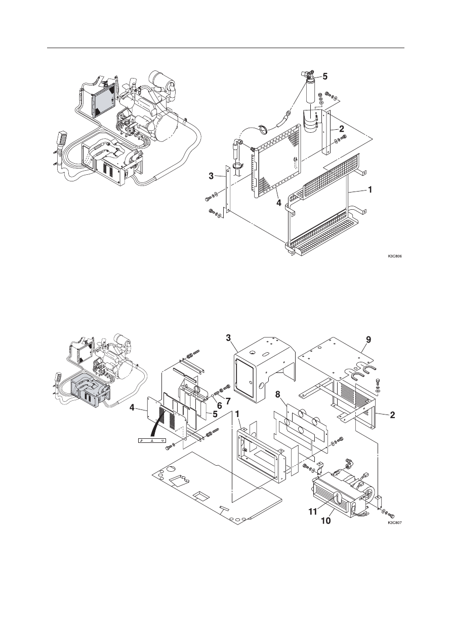
Condenser Assembly

  1. Cover
  2. Bracket

  3. Bracket
  4. Condenser

Air Conditioner Unit (1/4)

  1. Box
  2. Box
  3. Box

  5. Dryer

  4. Cover
  5. Damper
  6. Ball

  7. Spring
  8. Plate
  9. Cover

10. Air Conditioner
11. Thermistor

MACHINE CONFIGURATION

AIR CONDITIONER SYSTEM

III-129

TB125, 135, 145

Air Conditioner Unit (2/4)

Air Conditioner Unit (3/4)

  1. Cover
  2. Plate
  3. Wire Harness

  4. Diode
  5. Wire
  6. Thermostat

  7. Switch
  8. Relay
  9. Lever

  1. Control Assembly
  2. Duct
  3. Duct

  4. Wire Harness
  5. Diode
  6. Duct

  7. Hose
  8. Hose
  9. Hose

10. Louver
11. Hose
12. Hose

10. Diode

MACHINE CONFIGURATION

AIR CONDITIONER SYSTEM

III-130

TB125, 135, 145

Air Conditioner Unit (4/4)

  1. Joint
  2. Cover
  3. Plate
  4. Lever
  5. Boss

  6. Filter
  7. Valve
  8. Hose
  9. Hose
10. Hose

11. Hose
12. Bushing
13. Nipple
14. Valve

MACHINE CONFIGURATION

AIR CONDITIONER SYSTEM

III-131

TB125, 135, 145

 TB145: S/N 14511995~14512894

Compressor Assembly

A: Allow a clearance.
B: Press on the center of the belt with a finger. The belt’s

tension is normal if it bends about 8 mm when pressed
with a force of about 98N.

C:

 54.9 N·m

Apply thread-locking compound.

D:

 47.1 N·m

Apply thread-locking compound.

E:

 105.8 N·m

  1. Engine Foot
  2. Shaft
  3. Pulley
  4. Bracket

  5. Compressor
  6. Pulley
  7. Belt

MACHINE CONFIGURATION

AIR CONDITIONER SYSTEM

III-132

TB125, 135, 145

Condenser Assembly

  1. Cover
  2. Bracket

  3. Bracket
  4. Condenser

Air Conditioner Unit (1/4)

  1. Box
  2. Box
  3. Box

  5. Dryer

  4. Cover
  5. Damper
  6. Louver

  7. Cover
  8. Cover
  9. Damper

10. Air Conditioner
11. Thermistor
12. Wire Harness

MACHINE CONFIGURATION

AIR CONDITIONER SYSTEM

III-133

TB125, 135, 145

Air Conditioner Unit (2/4)

Air Conditioner Unit (3/4)

  1. Cover
  2. Plate
  3. Wire Harness

  4. Diode
  5. Wire
  6. Thermostat

  7. Switch
  8. Relay
  9. Lever

  1. Control Assembly
  2. Duct
  3. Wire Harness

  4. Diode
  5. Defroster
  6. Hose

  7. Hose
  8. Hose
  9. Louver

10. Hose
11. Hose

10. Diode

MACHINE CONFIGURATION

AIR CONDITIONER SYSTEM

III-134

TB125, 135, 145

Air Conditioner Unit (4/4)

  1. Joint
  2. Cover
  3. Plate
  4. Lever
  5. Boss

  6. Filter
  7. Valve
  8. Hose
  9. Hose
10. Hose

11. Hose
12. Bushing
13. Nipple
14. Valve

MACHINE CONFIGURATION

AIR CONDITIONER SYSTEM

III-135

TB125, 135, 145

 TB145: S/N 14512895~14513260

Compressor Assembly

A: Allow a clearance.
B: Press on the center of the belt with a finger. The belt’s

tension is normal if it bends about 8 mm when pressed
with a force of about 98N.

C:

 54.9 N·m

Apply thread-locking compound.

D:

 47.1 N·m

Apply thread-locking compound.

E:

 105.8 N·m

  1. Compressor
  2. Pulley
  3. Pulley

  4. Shaft
  5. Collar
  6. Belt

MACHINE CONFIGURATION

AIR CONDITIONER SYSTEM

III-136

TB125, 135, 145

Condenser Assembly

  1. Bracket
  2. Condenser
  3. Dryer

  4. Bracket
  5. Hose
  6. Hose

Air Conditioner Unit (1/4)

  1. Louver
  2. Cover

  7. Hose
  8. Presser Switch
  9. Bracket

MACHINE CONFIGURATION

AIR CONDITIONER SYSTEM

III-137

TB125, 135, 145

Air Conditioner Unit (2/4)

Air Conditioner Unit (3/4)

  1. Cover
  2. Duct
  3. Connector

  4. Control Panel
  5. Hose
  6. Hose

  7. Hose
  8. Hose

  1. Air Conditioner unit
  2. Hose

  3. Hose
  4. Wire Harness

MACHINE CONFIGURATION

AIR CONDITIONER SYSTEM

III-138

TB125, 135, 145

Air Conditioner Unit, Control Panel

  1. Air Conditioner Unit
  2. Motor Assembly
  3. Thermostat
  4. Resistor
  5. Core
  6. Valve

  7. Wire Harness
  8. Control Panel
  9. Control Cable
10. Switch
11. Rotary Switch

MACHINE CONFIGURATION

AIR CONDITIONER SYSTEM

III-139

TB125, 135, 145

 TB145: S/N 14513261~

Compressor Assembly

A: Allow a clearance.
B: Press on the center of the belt with a finger. The belt’s

tension is normal if it bends about 8 mm when pressed
with a force of about 98N.

C:

 54.9 N·m

Apply thread-locking compound.

D:

 47.1 N·m

Apply thread-locking compound.

E:

 105.8 N·m

  1. Compressor
  2. Pulley
  3. Pulley

  4. Shaft
  5. Collar
  6. Belt

MACHINE CONFIGURATION

AIR CONDITIONER SYSTEM

III-140

TB125, 135, 145

Condenser Assembly

  1. Bracket
  2. Condenser
  3. Dryer

  4. Bracket
  5. Hose
  6. Hose

Air Conditioner Unit (1/4)

  1. Louver
  2. Cover

  7. Hose
  8. Presser Switch
  9. Bracket

MACHINE CONFIGURATION

AIR CONDITIONER SYSTEM

III-141

TB125, 135, 145

Air Conditioner Unit (2/4)

Air Conditioner Unit (3/4)

  1. Cover
  2. Duct
  3. Connector

  4. Control Panel
  5. Hose
  6. Hose

  7. Hose
  8. Hose

  1. Air Conditioner unit
  2. Hose

  3. Hose
  4. Wire Harness

MACHINE CONFIGURATION

AIR CONDITIONER SYSTEM

III-142

TB125, 135, 145

Air Conditioner Unit, Control Panel

  1. Air Conditioner Unit
  2. Motor Assembly
  3. Thermostat
  4. Resistor
  5. Core
  6. Valve

  7. Wire Harness
  8. Control Panel
  9. Control Cable
10. Switch
11. Rotary Switch

III-143

TB125, 135, 145

Overview of System Operation

• Truck and Heavy Equipment Systems
• Air Conditioner-System Operation
• Heater System Operation
• Environmental Effects on System Operation
• Chapter Review

Truck and Heavy Equipment Systems

A variety of HVAC systems are in use today, some old and some new. There are:

• Vehicle manufacturer installed systems

• Owner specified systems

• Add-on systems

• Retrofit systems

The system components come in different colors, shapes, and sizes. They may be
mounted in or on the cab in varied locations. Owners or fleet maintenance people can
modify systems by adding controls, auxiliary units or ducts. Major components are
sometimes replaced due to damage or failure. All systems were, at least originally,
designed and installed to meet the needs of an operator. Figure 2-1 includes
illustrations of various AC and Heater systems. They illustrate system advantages
and disadvantages explained in the paragraphs that follow.

The HVAC system includes both heater and air conditioner components, usually

a common control, and air ducts. The system cools the cab by removing heat energy.
It removes moisture from damp air in the cab and adds fresh outside air to the cab.
In this way, the operator can work comfortably in all kinds of weather.

A sleeper unit, built in or added on, increases the air volumes in the cab. The air

conditioner or heater must circulate and cool or heat a larger amount of air. This is
accomplished by routing ducts and controls to the sleeper compartment as part of
system design. Components may be increased in size to handle the larger cab air
volume. A bigger heater core, air conditioning evaporator coil, condenser, blower or
fan may be included. Often, on long haul trucks, auxiliary air conditioning and heater
components and controls are added. The objective remains the same, to move heat
energy and maintain occupant comfort.

Click on any of these

subject headings to go

directly to the page


Content      ..     11      12      13      14     ..